Stowage and Arrangement of the cargo, that are Non-Standardized, always demand special preparation. This article provides calculation, norms, and costs.
The Method of Calculation of Non-shift Criterion for Structurizing Cargoes
Definition
Non-Standardized Cargo (according to the IMO terminology) means a cargo, which requires individual stowage and securing arrangements.
Non-standardized cargoes are subdivided into two groups to ensure their securing:
- cargo units;
- cargo structures (structurizing cargoes).
Cargo units are cargoes, stowage and securing of which are performed in an individual manner by connecting each separate cargo unit to the ship’s hull.
All the rest non-standardized cargoes are considered as cargo structures (structurizing cargoes), which being stowed on a ship, arrange discrete structures – bodies (stacks).
A cargo structure is a discrete structure, comprising of separate packages, metal rolled products, pig iron, metal scrap and so on (of general or break-bulk cargo) stacked according to the given stowage pattern. The properties of cargo structures depend not only on the characteristics of individual cargo elements, but also on the order, direction and method of their stowage. One and the same cargo, stowed by using different patterns, generate different structures, which possess different properties, including resistance to shift due to external forces.
Static stability angle χ of a structure is used as a measuring criterion of ability of a stack of a structurizing cargo to resist shift. It is an acute angle between the horizontal plane and the inclining bottom plane of the structure at the initial moment of its collapse in any form:
- tipping,
- sliding or loss of stability of the structure.
Examples of coils stowage patterns in the upper tier of a stack at different Static Stability Angles χ are given below:


Original researches have been made to determine static stability angles χ for different kinds of structuring cargoes, the values of which are given in the national Rules for safe sea carriage of particular kinds of general cargoes. For each structure pattern the value of static stability angle χ should be determined in accordance with this article Rules for Safe Transportation of Cargoes by Sea on the Cargo Ship“Rules and Requirements for Safe Cargo Carriage by Sea”, to the present Rules, and be indicated by the elaborator of the Cargo Information.
Non-shift Criterion
Safe carriage by sea of Structurizing cargo is estimated with the help of the Non-shift Criterion in the following formula:
where:
- Θs – cargo structure dynamic stability angle, deg,
Θs = F(χ, τr, sea navigation area); - τr – rolling period of the ship with cargo, sec;
- Θdyn – rolling amplitude of the ship with cargo in holds, or dynamic heeling angle of the ship with cargo on the upper deck (or high above-water sided ship) during rolling beam on to the resonance heaving, corresponding to the sea navigation area of the ship, which is not run, deg,
Θdyn = F(h0, sea navigation area); - h0 – initial metacentric height of the ship with cargo, m.
Cargo Structure Dynamic Stability Angle Θs – is determined on the basis of the known Cargo Structure Static Stability Angle χ, taking into account the nature of the ship’s loading and sea navigation area, which define the dynamics of the ship’s rolling and pitching.
Read also: Rules for Safe Transportation of Cargoes by Sea on the Cargo Ship
Depending on the location of the surface of shifting of a stack of the cargo (above the ship’s centre of gravity or below it), two different dynamic models are applied, and each of them consists of two variants:
- on the basis of the rolling amplitude of a low above-water sided ship;
- on the basis of the dynamic heeling angle of a ship with large side windage area.
When transporting the cargo, whose surface is above the ship’s centre of gravity, Θs – cargo dynamic stability angle should be determined according to the diagrams with the respective χ or by solving, in relation to Θs (in radians), the following equations.
On the basis of the rolling amplitude of a low above-water sided ship:
On the basis of the dynamic heeling angle of a ship with large side windage area:
When transporting a cargo, the surface of which is below the ship’s centre of gravity, Cargo Dynamic Stability Angle Θs should be determined by diagrams with the respective χ or by solving in relation to Θs the following equations.
On the basis of the lolling amplitude of a low above-water sided ship:
On the basis of the dynamic heeling angle of a ship with large side windage area:
where:
- τr – rolling period of a ship with cargo, sec;
- χ – cargo static stability angle, deg.;
- g – acceleration of gravity, g = 9,81 м/с2;
- r0 – semi-height if a wave, corresponding to the sea navigation area, m;
- z – vertical distance between the cargo shifting surface and the ship’s centre of gravity, m.
Dynamic heeling angle Θdyn and the rolling amplitude of the ship for non-shift criterion calculation should be determined by the following method.
There are the following accepted definitions for sea navigation areas:
- Unrestricted – navigation in oceans and sea areas at seas with design value of wave height with 3 % probability of 11 m;
- Restricted I – navigation in sea areas at seas with a wave height with 3 % probability of exceeding 8,5 m and with the ships proceeding not more than 200 miles away from the place of refuge and with an allowable distance between the places of refuge not more than 400 miles;
- Restricted II – navigation in sea areas at seas with a wave height with 3 % probability of exceeding 7,0 m, with ships proceeding from the place of refuge not more than 100 miles and with an allowable distance between the places of refuge not more than 200 miles;
- Restricted II СП – river-sea navigation at seas with a wave height with 3 % probability of exceeding 6,0 m with ships proceeding from the place of refuge:
- in open seas up to 50 miles and with an allowable distance between the places of refuge not more than 100 miles;
- in enclosed seas up to 100 miles and with an allowable distance between the places of refuge not more than 200 miles;
- Restricted III СП – river-sea navigation at seas with a wave height with 3 % probability of exceeding 3,5 m with due regard for particular restrictions on the area and conditions of navigation resulting from the wind and wave conditions of the basins with determination of a maximum allowable distance from the place of refuge which in no case should be more than 50 miles;
- M-СП – river-sea navigation with a wave height with 3 % probability of exceeding 3,5 m at sea regions according to the ship’s Class Certificate.
Calculation of the heeling moment caused by wind pressure
The heeling moment Mv, kN·m, is assumed to be equal to the product of wind pressure рv, Pa, by windage area Av, m2, and by the distance z, m, between the centre of windage area and the actual waterline plane:
The value of heeling moment is assumed to be constant over the whole ship’s heeling period.
The values of wind pressure рv, should be taken from table 1 depending upon the ship’s sea navigation area and the arm of windage area, z in m.
| Table 1. Wind pressure pv, Pa | ||||||||||||||
|---|---|---|---|---|---|---|---|---|---|---|---|---|---|---|
| Navigation area | z, m | |||||||||||||
| 0,5 | 1,0 | 1,5 | 2,0 | 2,5 | 3,0 | 3,5 | 4,0 | 4,5 | 5,0 | 5,5 | 6,0 | 6,5 | 7,0 & over | |
| Unrestricted | – | 706 | 785 | 863 | 922 | 971 | 1 010 | 1 049 | 1 079 | 1 108 | 1 138 | 1 167 | 1 196 | 1 216 |
| Restricted I | 0,567 of the wind pressure value adopted for the unrestricted service | |||||||||||||
| Restricted II | 0,275 of the wind pressure value adopted for the unrestricted service | |||||||||||||
Calculation of the amplitude of roll
The amplitude (in deg.) of roiling of a ship with a round bilge, which doesn’t have bilge keels and a bar keel should be calculated according to the formula:
where:
- X1, X2 – non-dimensional factors;
- Y – factor in deg.
The values of factor Y shall be taken from Table 2 depending on the ship’s navigation area and
ratio.
| Table 2. Factor Y and design value of wave height | |||||||||||
|---|---|---|---|---|---|---|---|---|---|---|---|
| Navigation area | Assumed waves height, m | ||||||||||
| 0,04 & less | 0,05 | 0,06 | 0,07 | 0,08 | 0,09 | 0,10 | 0,11 | 0,12 | 0,13 & above | ||
| Unrestricted | 11,0 | 24,0 | 25,0 | 27,0 | 29,0 | 30,7 | 32,0 | 33,4 | 34,4 | 35,3 | 36,0 |
| Restricted I | 8,5 | 19,0 | 20,0 | 22,4 | 25,1 | 27,4 | 29,2 | 30,8 | 32,0 | 32,9 | 33,5 |
| Restricted II | 7,0 | 16,0 | 17,0 | 19,7 | 22,8 | 25,4 | 27,6 | 29,2 | 30,5 | 31,4 | 32,0 |
The values of factor X1 shall be taken from Table 3 depending upon B/d ratio, where:
- B – breadth of the ship, m;
- d – draught, m.
| Table 3. Factor X1 | |||
|---|---|---|---|
| B/d | X1 | B/d | X1 |
| 2,4 and below | 1,0 | 3,0 | 0,90 |
| 2,5 | 0,98 | 3,1 | 0,88 |
| 2,6 | 0,96 | 3,2 | 0,86 |
| 2,7 | 0,95 | 3,3 | 0,84 |
| 2,8 | 0,93 | 3,4 | 0,82 |
| 2,9 | 0,91 | 3,5 and above | 0,80 |
The values of factor X2 shall be taken from Table 4 depending upon the ship’s total block coefficient СB.
| Table 4. Factor X2 | ||||||
|---|---|---|---|---|---|---|
| CB | 0,45 and below | 0,5 | 0,55 | 0,6 | 0,65 | 0,7 and above |
| X2 | 0,75 | 0,82 | 0,89 | 0,95 | 0,97 | 1,0 |
If the ship has bilge keels or a bar keel, or both, the rolling amplitude, in deg., should be calculated by the formula:
where:
- k – factor, which is accepted according to table 5, depending upon ratio Ak/LB;
- Ak – total overall area of bilge keels, or lateral projection area of the bar keel, or a sum of these areas, m2;
- L – length of the ship between the perpendiculars, m.
| Table 5. Factor k | ||||||||
|---|---|---|---|---|---|---|---|---|
| 0 | 1,0 | 1,5 | 2,0 | 2,5 | 3,0 | 3,5 | 4,0 and above | |
| k | 1,00 | 0,98 | 0,95 | 0,88 | 0,79 | 0,74 | 0,72 | 0,70 |
Bilge keels are not to be taken into consideration where ships have the ice category in their class notation.
The value of rolling amplitude for a ship having a sharp bilge should be assumed to be equal to 70 % of the amplitude, calculated according to formula 7.
The rolling amplitude of ships provided with anti-roll devices should be determined taking no account of operation of these devices.
The calculated values of the rolling amplitude should be rounded off to the tenth of degrees.
Calculated values of the roiling amplitude for river-sea navigation ships should be determined in the same way as for the ships of Restricted II navigation area or according to individual methods approved in the established order.
Determination of the ship’s dynamic heeling angle at simultaneously action of a suddenly applied moment of wind squall and the ship’s roiling
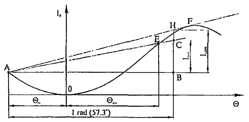
The maximum dynamic heel occurs, if at the instant of sudden application of heeling moment, the ship had the largest list towards the opposite side caused by rolling. In order to determine the dynamic heel angle, the diagram of the dynamic stability should be extended in the direction of the negative abscissa, and point A corresponding to the amplitude of rolling Θm should be fixed on it. Then a straight line should be drawn from point A parallel to the axis of abscissa, and segment AB, equal to one radian (57.3°), should be laid off on it. From point B segment BC, equal to the lever of the given heeling moment lheel should be laid off perpendicularly upwards. The abscissa of point E at the crossing of the straight line AC with the diagram of dynamic stability indicates the required dynamic heeling angle Θdyn.
The longitudinal stability of cargo units and stacks of structurizing cargoes should be additionally checked at the calculated pitch amplitude of the ship or at arbitrarily calculated value of static trim angle of 17°. Such inspection should be carried out taking into account the friction coefficients of the used materials and keeping the balance of the respective moments.
If, as a result of a calculation according to formula 1, non-shift criterion’s value of the cargo proves to be less than 1,0, it indicates that the necessity of its securing exists, specifying that the strength of the securing devices from each side of the ship is determined by the load Q, t(f), arising in case the dynamic heeling angle exceeds the cargo dynamic stability angle and is calculated according to the formula:
where:
- n – quality of cargo units to be secured, pcs.;
- P – average mass of a cargo unit, t.
The quantity of the required lashings N is determined by the scheme of their attachment and safe (maximum) working load SWL or breaking load BL (see tables below).
In case a lashing line coincides with the direction of load’s action, this quantity N of the required lashings per each part of the cargo to be secured is determined by the scheme of their attachment and their safe (maximum) working load (SWL), if the cargo is stowed in cargo compartments, or their breaking load (BL), if the cargo is stowed on the upper deck and hatch covers, by the formula:
The Standards for strength of Cargo Securing Devices and Approximate consumption of them
| Table 6. The Standards for Strength of Cargo Securing Devices | ||||
|---|---|---|---|---|
| Kind of device | Safe (Maximum) Working Load SWL | Proof load PL | Breaking load BL | Safety factor k |
| Wire Rope, single use | 0,8 BL | 1,00 SWL | 1,25 SWL | 1,25 |
| Wire Rope, re-useable | 0,33 BL | 1,25 SWL | 3,0 SWL | 3 |
| Chain lashings | 0,5 BL | 1,25 SWL | 2,0 SWL | 2 |
| Shackles, eye rings and eye plates, turnbuckles of mild steel | 0,5 BL | 1,25 SWL | 2,0 SWL | 2 |
| Other devices | 0,5 BL | 1,25 SWL | 2,0 SWL | 2 |
| Steel band, single use | 0,5 BL | – | 2,0 SWL | 2 |
| Table 7. Approximate consumption of Cargo Securing Materials and Devices per 1 t of cargo | ||||||
|---|---|---|---|---|---|---|
| Cargo | Timber, m3 | Wire, kg | Nails, kg | Rope, m | Turnbuckles, pcs. | Clamps, pcs. |
| Metal products | 0,020 | 3,4 | 0,080 | 6,0 | 0,8 | 2 |
| Vehicles of up to 2 t | 0,005 | 2,6 | 0,300 | 6,0 | 1,2 | 7 |
| Vehicles of from 3 to 12 t mass | 0,008 | 2,4 | 0,100 | 3,6 | 2,0 | 7 |
| Vehicles of above 12 t mass | 0,009 | – | 0,060 | 1,2 | 0,6 | 2 |
| Steel pipes of big diameter | 0,020 | – | 0,060 | 2,8 | 0,6 | 3 |
| Large-dimensional cargoes of cylindrical shape | 0,008 | – | 0,080 | 2,5 | 0,6 | 4 |
| Metal barrels and drums | 0,005 | 2,5 | 0,006 | – | – | – |
| Break bulk cargoes, boxes, sacks, etc. | 0,002 | – | 0,02 | – | – | – |
| Boxes and unpackaged equipment of 2-20 t mass | 0,020 | 2,1 | 0,400 | 4,0 | 0,6 | 2 |
| Equipment of above 20 t mass | 0,020 | – | 0,400 | 3,2 | 0,6 | 3 |
| On average | 0,011 | 1,3 | 0,087 | 3,0 | 0,7 | 3 |