Quality of LNG is one of the most significant issues in gas trading. This article covers quality regulations of Liquefied Natural Gas.
Wobbe index
In the LNG terminal, the quality specification of the delivery gas must comply with the specifications set by pipeline transmission companies and end users to ensure operational safety, reliability, and compliance with environmental regulations. The typical specifications used in most US gas pipeline tariffs are based on meeting the heating value (or gas calorific value) and the gas component composition ranges. However, most combustion devices, such as gas turbines or burners, are designed specifically for a narrow range of gas compositions (or Wobbe Index values) to limit NOx emissions.
Wobbe Index (WI) originally was developed to characterize the similarity of gas mixtures based on the heat release from combustion. It is derived from the fluid dynamic principle, which correlates the heat release from combustion with the heating value and density of the gas. Wobbe Index is used in the gas turbine industry for fuel gas specification and gas turbine performance guarantee. It is also one of the specifications for gas interchangeability required for pipeline distribution. The index is calculated by dividing the higher heating value of the gas by the square root of the gas density or MW (molecular weight) relative to air.
Wobbe Index is internationally the most widely accepted measure of gas interchangeability. Wobbe Index is frequently used as a parameter to determine the upper and lower limits of gas composition specified in gas sales or import contracts.
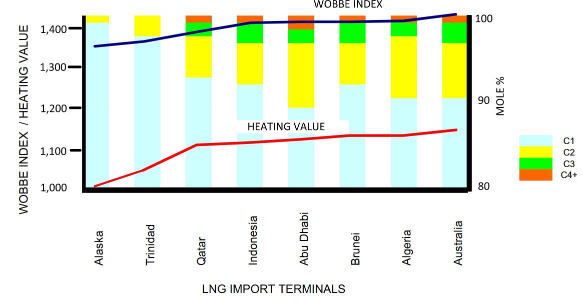
Historically, each gas market has been isolated from other regions with its own indigenous and gas supply mix, and each market has its own gas quality specifications. In the United States and Western Europe, most of the LPG components are extracted for sales as liquids, and the residual gas is sold to consumer pipeline; consequently, the gas compositions and heating values do not vary very much. However, as shown in Picture 1, the LNG compositions and heating values vary significantly among different export terminals, and there are concerns regarding the gas interchangeability with the local gas contents (see Picture 1).
From the producers perspectives, it is necessary to meet the export requirements for the contracted quality, which is typically met by integrating an NGL extraction facility to the liquefaction plant. For the LNG receiving terminals, they must be equipped with a processing facility, especially for spot market cargoes, with provisions that allow them to adjust the heating value or Wobbe Index to meet the pipeline gas specification.
Wobbe index control
The common approach to reduce the Btu value and Wobbe Index of a gas is by diluting the vaporized LNG with nitrogen, up to the pipeline limit for inert content, usually 2 to 3 %. Nitrogen is an effective medium for lowering the heating value of the pipeline gas. The addition of nitrogen also increases the molecular weight of the gas mixture that further lowers the Wobbe Index value.
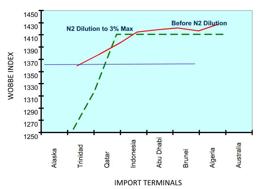
For example, for California pipeline gas, the gas specification must meet the 1 360 Wobbe Index specification, which is the specification of existing combustion equipment and power generation stations. To meet the California Wobbe Index specification, Alaska LNG is the only gas that meets the low Wobbe Index specification without nitrogen dilution.
For the Trinidad LNG, about 1 mole % nitrogen is required. For other LNGs, because of the maximum 3 mole % nitrogen limit, less than 40 % of the LNG sources would meet the California specification, as shown in Picture 2.
Due to the stringent Wobbe Index specification, weathering of LNG must be monitored in the regasification terminal. The heating value and Wobbe Index will gradually increase due to boil-off of the nitrogen components during transit and storage. For the marginal Wobbe Index LNG, the weathering effect may result in off-specification natural gas product.
Some regasification terminals are equipped with the capability of injecting either nitrogen or LPG to regulate the send out gas heating value. In North America and the United Kingdom, the pipeline gas typically has a relatively low Btu value, and nitrogen dilution for lowering the Btu value is common. In Japan and most Asian LNG countries, where high Btu gas is desirable, propane can be injected into the gas pipeline to raise its calorific value.
There are various nitrogen injection schemes, which range from simple gaseous pipeline injection to the dual practice of gaseous and liquid nitrogen injections. However, introducing gaseous nitrogen at low pressure by mixing and condensing by the send out liquid can eliminate vapor compression and is potentially the least costly option. However, it would require sufficient cold LNG send out available for condensation (Huang et al., 2005; Coyle et al., 2007).
The calorific value reduction by injection of nitrogen is limited by the inert limit of the sendout gas (Picture 2). Nitrogen injection alone may not be sufficient for adjusting the quality for the very rich LNG compositions. In cases where nitrogen dilution cannot meet the heating value requirement, NGL components (ethane, propane, and butane and heavier hydrocarbon) need to be removed from the regasified LNG. If the NGL value is at a premium over natural gas, NGL recovery makes economic sense rather than nitrogen dilution. However, if the economics of NGL recovery is not there, then nitrogen injection is the only choice, or by diluting with a leaner LNG source.
There are several NGL recovery configurations that can be used for fractionating the NGL components from the import LNG. The NGL recovery process can be designed to utilize the cold energy from LNG vaporization to provide reflux in fractionation, and is very energy efficient (Mak, 2008).The configuration selection depends on many factors, including the heating value range of the import LNG, the values of the LPG liquid product and ethane product, the capital cost and operating cost, and the feasibility of integrating to an existing regasification terminal (Cuellar et al., 2007).
For LNG that has very high ethane content, and where there is no market for ethane product, an interesting option is using the Catalytic De-Richment (CDR) process (by Johnson Matthey catalysts), which can convert the higher hydrocarbons into methane. The CDR process was originally developed to produce pipeline gas from naphtha, based on steam reforming, CO shifting, and the methanation process to produce methane. Although the CDR option can convert all the higher hydrocarbons into methane, the capital and operating costs of such or similar processes are high and are not economical for LNG import terminals (Carnell et al., 2008). In most markets NGLs are more valuable than methane so this process is not commonly used.
LNG terminal operation flexibility
In addition to the process systems, an LNG terminal requires utility and offsite supports and power supply, and pipeline infrastructure to safely and reliably delivering on-specification gas to the customers.
LNG receiving terminals operate quite differently among different regions of the world. In the United States and Western Europe, LNG receiving terminals are base load plants and are designed to deliver natural gas to the pipelines at a fairly constant rate. These regions have large natural gas surge capacity because of the extensive pipeline network. During low demands when excess gas is produced, pipelines can be packed to store the gas, and underground caverns can also be used for temporary storage. The large surge capacity allows the LNG terminal to operate at a fairly constant rate even during low demand seasons.
However, in other regions of the world, such as in China, where there is a lack of pipeline infrastructure and gas storage capacity, the LNG receiving terminals must adjust their sendout rates to meet the gas consumption. Gas demands typically peak during the day and drop significantly during the night. There are also seasonal variations. Operating these terminals requires frequent startup and shutdown of the sendout pumps and vaporizers.
In addition, the large sendout rates, the frequent ship unloading, spot market LNG cargoes, and variations in LNG compositions all make these newer plants more difficult to operate. These LNG import terminals must be designed with more robustness and be provided with flexibility to accommodate these challenging operating parameters.
LNG cold utilization
Approximately 8 to 10 % of the energy in natural gas is consumed in the LNG liquefaction process and during LNG transport. In a typical LNG liquefaction plant, it takes about 230 kW to liquefy one MMscfd of natural gas. About 280 MW of power is consumed in a 1 200 MMscfd liquefaction plant. Theoretically, some of the power consumed in LNG liquefaction is recoverable at the LNG receiving terminal if the LNG is used as a refrigerant for industrial use or as a heat sink in power generation.
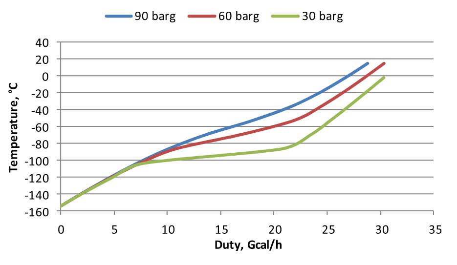
However, the main difficulty in fully utilizing the “LNG Cold” for cooling is to identify users that can use the different temperature levels of refrigeration released during LNG regasification. The heating curves of LNG at three different pressures are shown in Picture 3. The available low temperature refrigeration is higher at 30 barg than at 90 barg. To efficiently utilize the LNG cold, the cooling curves of the users must closely match the heating curve of LNG. This is the same concept used in the design of the refrigeration cycle. Therefore, unless the LNG terminal is located in an industrial complex, it is difficult to find suitable users that can take full advantage of the LNG cold.
From a thermodynamic point of view, the most efficient use of LNG is in cooling and as a refrigerant to provide cooling in refinery and petrochemical complexes, such as in air separation, carbon dioxide production, vapor recovery, chilled water production, and hydrocarbon fractionation. More discussions on the subject of LNG cold utilization can be found in Chapter 10.
Alternatively, the refrigeration content in LNG can be used as a cold heat sink to generate power. This may not be the most efficient use, but integration to a power plant can eliminate seawater or fuel gas consumption required in regasification since low level waste heat from the power plants are readily available (Mak, 2005). To bring the “LNG Cold” to the users, an intermediate heat transfer fluid is required using a closed circuit in transferring the refrigerant to the users. To minimize the transfer costs, the LNG terminal must be located at the industrial complex, as in Japan’s LNG terminals and in the Jurong Island Terminal in Singapore.
Cryogenic power generation
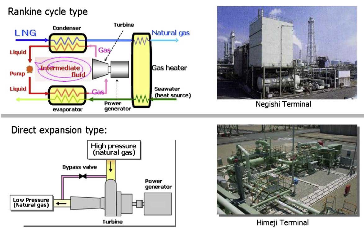
The use of LNG for power plant fuel supply has been proven for many years in Japan. Information relating to some of Japan’s gas-fired power plants and their capacities are shown in Table 1.
Principle of organic rankine cycle (ORC)
The principle for power generation with LNG is based on the Rankine cycle as today’s steam-turbine-driven power plants. The ideal Rankine cycle efficiency (or Carnot cycle efficiency) can be defined as (T2-T1)/T2. T2 is defined as the absolute temperature of the heat source and T1 is the absolute temperature of the heat sink.
Note that T1 is actually the average vaporization temperature of LNG, which ranges from -250 °F to ambient temperature.
Because of the extremely low temperature of LNG, even with a low-level heat such as seawater orturbine exhaust, significant power can be generated using the Rankine cycle concept. In simple terms,the power cycle generation efficiency can be increased almost proportionally to the temperature difference between:
- the heat source (hot side);
- and the heat sink (cold side).
The Organic Rankine cycle (ORC) operating principal is illustrated in a temperature-entropy (T-S) diagram (Picture 4). Typically, a hydrocarbon is used as the working fluid, such as propane or butaneor a mixed hydrocarbon. In the cycle, the fluid is liquefied using the refrigeration released during LNG vaporization.
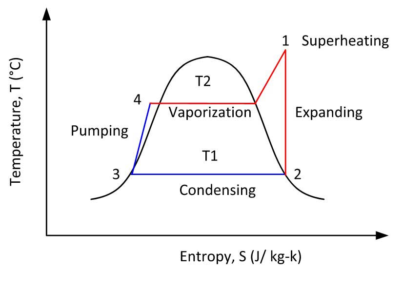
The vaporized LNG is piped to the gas consumers while the intermediate fluid is pumped, vaporized, superheated, and then expanded in an expander to a lower pressure, generating power to drive a generator. The low pressure propane vapor is then recondensed by LNG and the cycleis repeated.
Closed rankine cycle
The Organic Rankine cycle can be operated using propane or butane as the working fluid in a closed cycle configuration (Picture 5). It basically goes through a typical Rankine cycle of condensing, pumping, heating, and expanding steps.
In addition, since the LNG sendout pump is designed to discharge at 8 to 10 MPag, and the fuel gas pressure to gas turbines is required at 3 to 5 MPag, the high pressure natural gas can be further heated and expanded to recover more power using a gas expander generator.
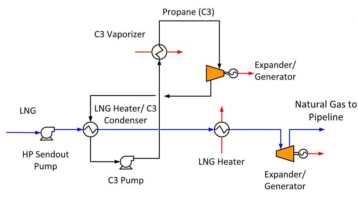
A combination of the ORC and natural gas expander (Picture 6) can significantly improve the overall power generation efficiency. This type of power generation operation has been proven in several applications in Japan’s LNG terminals.
Open rankine cycle
LNG itself can also be used as a working fluid in an open cycle configuration as shown in Picture 7 (Mak, 2005). In this configuration, only the low temperature portion of the LNG heat curve is used. The T1 (the average temperature at which the heat sink is used) is very low; hence a very high Rankine cycle efficiency can be achieved. With a more efficient cycle, the working fluid circulation can be reduced, lowering the operating cost of the cycle. This process does not use the warmer portion of LNG heat curve, and the residual cold can be further utilized by other cold consumers.
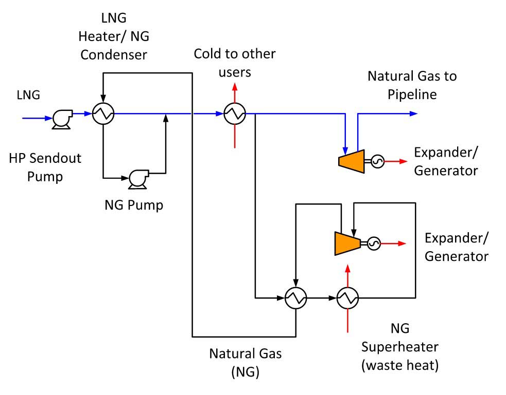
In the Open Rankine cycle, vaporized LNG is used as the working fluid. The working fluid is condensed in the LNG heater/NG condenser at about 5 barg pressure, using the cold portion of the LNG vaporization curve. The working liquid is then pumped by the NG pump, combined with the heated LNG from the NG condenser, and further heated by supplying refrigeration to other users.
| Table 1. Japan’s Cryogenic Power Plants | ||||||
|---|---|---|---|---|---|---|
| Company and Terminal Names | No of Units | Start of Operation | Output (kw) | Type | LNG Consumption (t/h) | Delivery (MPa) |
| Osaka Gas, Senboku Daini | 1 | 12/1979 | 1 450 | Rankine | 60 | 3,0 |
| Toho Gas, Chita Kyodo | 1 | 12/1981 | 1 000 | Rankine | 40 | 1,4 |
| Osaka Gas, Senboku Daini | 1 | 2/1982 | 6 000 | Rankine/NG direct expansion | 150 | 1,7 |
| Kyushu Electric Power and Nippon Steel, Kitakyushu LNG | 2 | 11/1982 | 9 400 | Rankine/NG direct expansion | 150 | 0,9 |
| Chubu Electric Power, Chita LNG | 2 | #16/1983 | 7 200 | Rankine/NG direct expansion | 150 | 0,9 |
| #23/1984 | 7 200 | Rankine/NG direct expansion | 150 | 0,9 | ||
| Tohoku Electric Power, Nihonkai LNG | 1 | 9/1984 | 5 600 | NG direct expansion | 175 | 0,9 |
| Tokyo Gas, Negishi | 1 | 4/1985 | 4 000 | Mixed refrigerant Rankine | 100 | 2,4 |
| Tokyo Electric Power, Higashi Ogishima | 1 | #15/1986 | 3 300 | NG direct expansion | 100 | 0,8 |
| Osaka Gas, Himeji | 1 | 3/1987 | 2 800 | Rankine | 120 | 4,0 |
| Tokyo Electric Power, Higashi Ogishima | 2 | #29/1987 | 8 800 | NG direct expansion | 170 | 0,4 |
| #3/1991 | 8 800 | NG direct expansion | 170 | 0,4 | ||
| Osaka Gas Senboku Daiichi | 1 | 2/1989 | 2 400 | NG direct expansion | 83 | 0,7 |
| Chubu Electric Power, Youkkaichi | 1 | 12/1989 | 7 000 | Rankine/NG direct expansion | 150 | 0,9 |
| Osaka Gas, Himeji | 1 | 3/200 | 1 500 | NG direct expansion | 80 | 1,5 |
The LNG working fluid is then split off from the main flow circuit, routed to an exchanger, and heated in a superheater using waste heat prior to being expanded using an expander to generate power. The expanded working fluid is heat exchanged and then condensed in the NG condenser to repeat the cycle.
Although power generation using ORC might seem attractive, it must consider the various operations of the LNG terminals. In a typical LNG terminal, the LNG sendout rate varies with gas and power consumption, and the fluctuation can be quite significant from day to night, from season to season. Therefore while the Organic Rankine cycle is designed for the maximum sendout, it must also be operated at turndown.
Subsequently, only a fraction of the installed expander capacity can be utilized during periods of low consumption. The rate of return on investment of power generation must then be based on averaged annual output, which would reduce its economic attractiveness.
Integration with combined cycle power plants
Since a significant amount LNG import today is used to supply fuel gas to operate power generation plants, integration of the regasification facilities to the power plants is a natural progression. With the such integration, the power generation efficiency can be increased using LNG as the cold heat sink.
Cooling water consumption in the power plant can then be reduced and the heating duty for LNG vaporization can be supplied by waste heat from the powerplant, thus eliminating the use of seawater for LNG heating. More discussions on the integration of LNG plant and power plant approach are discussed in Chapter 10.