Steel fracture in LNG carriers poses significant risks due to the extremely low operational temperatures, which can drastically affect the material properties of the steel used in their construction. The steel needs to remain ductile and tough at temperatures as low as -162 degrees Celsius (-260 degrees Fahrenheit), where standard structural steels would become brittle and prone to fracturing. To address this, advanced metallurgical technologies are employed to develop special steels with enhanced low-temperature performance. These steels often contain higher concentrations of nickel and other alloying elements that improve their ability to resist the brittleness typical of lower temperatures. Natural gas structural analysis plays a critical role in this context, involving rigorous simulations and testing to predict and analyze the behavior of these materials under actual operating conditions. This analysis ensures that the steel’s integrity is maintained throughout the lifecycle of the LNG carrier, safeguarding against structural failures that could lead to catastrophic incidents.
- Hull Structural Analysis
- Safehull
- DLA Analysis
- Additional Considerations for Independent Tanks
- SFA Notation
- Steel Fracture Modes
- Fracture Mechanism
- Elastic Fracture
- Ductile Fracture
- Brittle Fracture
- Fatigue Fracture
- Creep Fracture
- Stress Corrosion Cracking
- Wear Failure
- Stability Analysis
- ABS Analysis
- Intact Stability
- Damage Stability
Steel fracture in LNG carriers is a critical concern due to the extreme cold of the liquefied natural gas, which can drastically lower the temperature of the steel used in the ship’s construction, making it susceptible to becoming brittle and fracturing. To counteract this, LNG carriers are specifically designed using steel grades capable of maintaining excellent toughness at cryogenic temperatures. Hull structural analysis is an integral part of this design process, employing advanced computational methods and finite element models to simulate and assess the hull’s performance under various stress conditions, including those caused by the LNG’s extreme cold. This ensures that the structure can withstand the thermal stresses without compromising on safety or integrity. Regular inspections and maintenance based on continuous monitoring of the hull’s condition are crucial to detect early signs of material degradation or damage, thereby preventing potential failures.
Hull Structural Analysis
Safehull
The SAFEHULL system is used in determining the hull scantlings and its applicability to LNGC’s is described under Module 6.
DLA Analysis
LNGC’s are designed and constructed using some of the most advanced technology available, most stringent and accurate construction methods to fulfill the 40 years life called for in Owners’ specifications. In addition to Safe Hull analysis, vessel’s structural design is evaluated using a Dynamic Loading Analysis (DLA). His is done using realistic modeling of envisioned loading conditions, known environmental factors and related data.
The DLA Analysis and its applicability to LNGC’s are further described under Module 6.
Additional Considerations for Independent Tanks
A primary consideration is that the way in which loads imposed by the cargo (weight, lateral pressure, dynamic loads) are transferred to the ship structures surrounding General Overview of LNG Cargo Tanks (Typical Operations)the cargo tanks is quite different.
In a membrane type LNGC, loads are transmitted directly with continuity to the inner hull through the insulation in a way similar to a tanker.
In the independent cargo tank ships, the tank(s) are completely independent of the ship structure and therefore its total loads, including its own weight are transmitted to the localized ship structures in way of the tank supports, saddles, anti lifting devices, (in a certain way similarly to a container ships). Accordingly, independent tank ships have specially strengthened local structures subjected to heavy localized loads, which, in turn, distribute these concentrated loads to the ships structures. This makes the model for the analysis and the behavior of the various structures quite different compared to a LNGC membrane type.
Independent tanks are considered as Type B independent tanks under The Origins of the IGC Codethe IGC Code when the suitability of the tank structure is examined with respect to plastic deformation, buckling, fatigue failure and crack propagation:
a) FATIGUE AND CRACK PROPAGATION ANALYSIS.
A detailed stress analysis will be made to identify stress levels in the tank. For all locations showing relative high stress levels, a detailed fatigue and crack propagation analysis will be performed. The crack propagation analysis is particularly important and mandatory in order to classify the independent cargo tanks as type “B“.
b) BUCKLING ANALYSIS.
The local buckling of the panels in the tank structure will be evaluated,considering loads from cargo pressure, including hull girder deflection effects on the tank. Buckling considerations are particularly important for the analysis of the Moss-Rosenberg tanks.
Figure 1 summarizes the analysis to be carried out for the anticipation of the crack propagation mode.

Additional considerations are given under Modules 6 and 7.
SFA Notation
The SFA (Spectral Fatigue Analysis) notation is granted where a spectral fatigue analysis is performed in accordance with advanced criteria. The SFA notation in the Record is followed by number between brackets, which indicates the minimum expected life of the ship (with increments of 5).
The SFA Analysis and its applicability to LNGC’s are further described under Module 6.
Steel Fracture Modes
Fracture Mechanism
Hull steel can fracture in different ways. Sometimes it is not easy to determine the reasons and the modes of the fractures due to the combination of various failure modes. In other words, in the majority of the cases, when there is a fracture, more than one failure mode is likely to be associated with the cause of the failure.
The following steel fracture modes are considered:
- Elastic failure.
- Ductile failure.
- Brittle failure.
- Fatigue failure.
- Creep failure.
- Stress corrosion failure.
- Wear failure.
Elastic Fracture
Two types of failure occur due to unsuitable elastic behavior in a material:
a) ELASTIC INSTABILITY.
If the elastic modulus E is too low, the component may deflect too much in service, making it unusable. Examples are moving parts such as engines and structures such as bridges. Alternatively some components may not deflect as much as they should do, or may require too much force to deflect by the required amount. Examples are switches and springs. These problems will become apparent instantly as soon as the load is applied, except in visco-elastic materials such as polymers, where elastic strain can build up gradually over time. Elastic deflection can be distinguished from plastic strain and creep strain because it is totally recoverable on removal of the load.
b) BUCKLING.
Though buckling leads to a failure by another mechanism (usually ductile failure), the process of buckling is essentially an elastic instability, which is controlled by the material’s elastic modulus. A classic example is the failure of slender columns loaded in compression. This type of failure generally occurs instantaneously; it can be difficult to predict because it depends on the shape of the part and how it is loaded and restrained.
Ductile Fracture
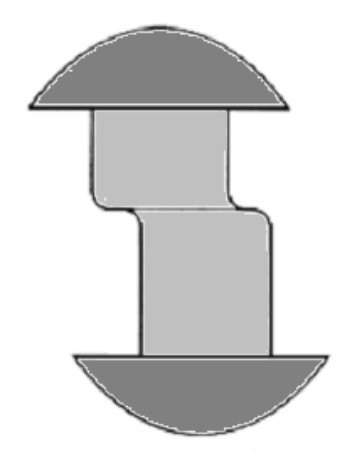
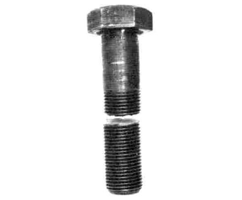
A failure is termed “ductile” if it occurs by plastic deformation, i. e. if the yield strength of the material is exceeded. This causes a permanent change in shape of the part, which becomes apparent if one attempts to reassemble broken components. Tensile stress causes necking, reducing the cross section of the part, as shown in the failed bolt at Figure 2.

Shear stress causes deformation of the type shown in the sketch of a failed rivet at Figure 3.
Some plastic deformation also occurs in other types of failure: for example fatigue failure always involves some plasticity, and brittle fracture may be preceded by plastic strain. However, in these cases the amount of plasticity is small: ductile fracture is characterized by gross plasticity, which leads to an obvious change in shape of the component.
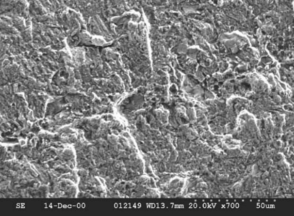
Figures 4 and 5 are two photos taken using a scanning electron microscope (SEM) showing the appearance of ductile fracture surfaces at high magnification. They have a distinctive “dimpled” appearance, the surface being covered with small dimples or craters. These dimples result from the fracture of spherical pores, which open up due to plastic deformation. The dimples may contain inclusions and other small particles from which the pores nucleated.
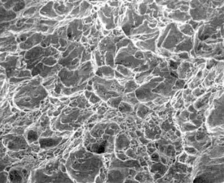
The above SEM photograph shows part of a fracture surface, at high magnification. The total width of this picture is about 50 µm (0,05 mm).
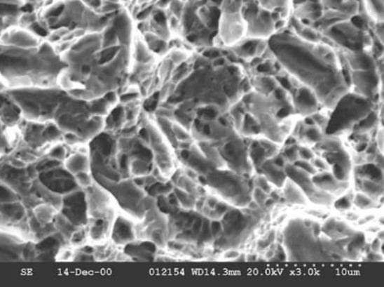
The above SEM photograph shows another ductile fracture surface. The dotted line (bottom left) shows the scale (in this case 10 µm).
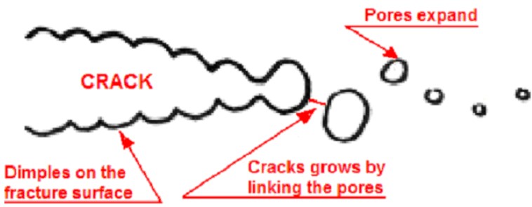
The appearance of the fracture surface at high magnification depends on the mechanism of crack propagation. Ductile crack extension occurs if the crack grows by causing local plasticity ahead of the crack tip, which pulls the material apart. Pores form and grow in the material just ahead of the crack. The crack grow occurs by linking of these pores as shown in Figure 6.
Brittle Fracture
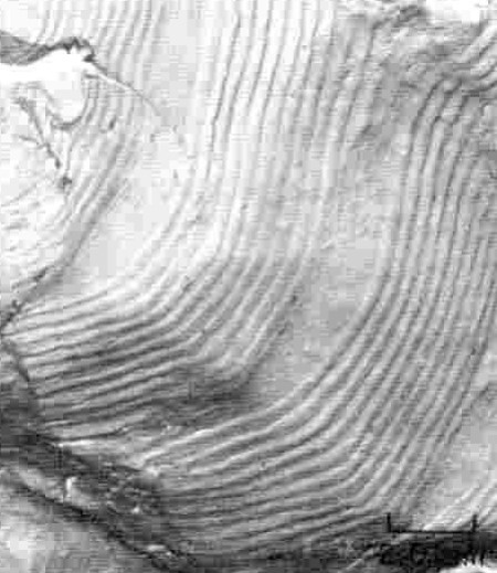
Brittle fracture is the term given to static failures caused by crack propagation. Crack propagation also figures in fatigue and creep failure, but brittle fracture occurs when a pre-existing crack propagates very rapidly through the material. Such fractures release a lot of energy and can be very loud, explosive and dangerous, as fragments of the material may be thrown long distances. In many cases, especially if the micro-mechanism of cracking is cleavage (see below), a macroscopic examination of the fracture surface may show lines (called “chevron marks“) which lead back to the failure origin. Figure 7 shows an example (the arrow shows the origin).
A big difference between brittle fracture and ductile fracture is that in brittle fracture there is no macroscopic deformation. So, the broken parts can be taken and put back together again, like making a jigsaw. This cannot be done after a ductile fracture because the shape of the pieces has changed. For example, the fracture of the bolt shown in Figure 8 may be compared with the one shown in Figure 2.
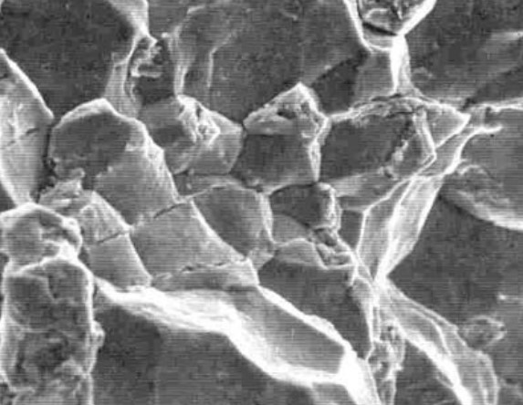
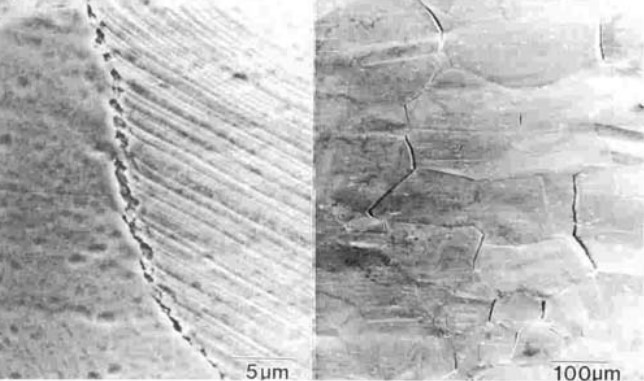
Brittle crack extension, also called “cleavage“, occurs by the splitting apart of planes in the atomic lattice. Each grain cleaves like a gemstone, giving a perfectly flat surface, as shown in Figure 9.
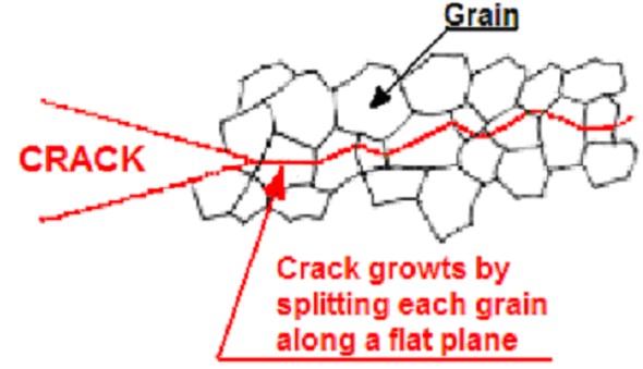
Because the cleavage plane for each grain will be at a different angle, the final fracture surface will consist of a series of small flat planes, each corresponding to one grain. Figure 10 shows what this looks like at high magnification.
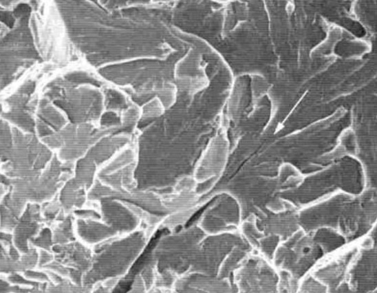
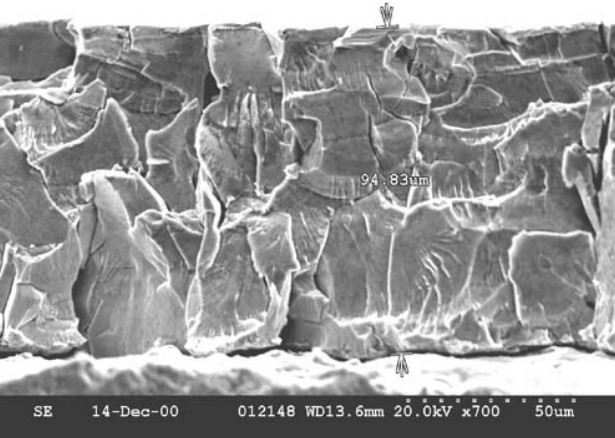
Figure 11 shows cleavage fracture in a surface coating of Cadmium (applied to a steel component to prevent corrosion and wear); the total thickness of the coating is about 95 µm.
The two mechanisms of crack extension described above are both “transgranular“, i. e. the crack grows through each grain. If,alternatively, the crack propagates by traveling around the grains (i. e. along the grain boundaries), then the mechanism is termed “intergranular“. Intergranular fractures can be either ductile or brittle; a brittle intergranular failure looks like it is shown in Figure 12.
Cleavage planes in Figure 12 are similar to those shown in Figure 9, but now they are outside of the grains. The existence of transgranular failure is often an indication that something is wrong with the material (e. g. an incorrect heat treatment causing a brittle phase to form on the grain boundaries). Most materials, in good condition, fail in the transgranular mode.
In a ductile intergranular failure, the outsides of the grains can be observed, but they have dimples on them as shown in Figure 13.

Ductile intergranular failures are quite rare. The only situation in which they commonly occur is creep. Also certain incorrect heat treatments applied to certain metal alloys can cause them to fail in this way even at room temperature, but the phenomenon is rare.
The existence of the cleavage mode is an indication that the crack grew very easily in the material, needing very little energy to propagate. This is often a clue to something wrong with the material, such as an incorrect heat treatment or the use of a sub-standard material. Some metals actually change from ductile fracture to brittle fracture at low temperature. This is the case of mild and high tensile steel used for ship construction. However some materials are just inherently brittle and will always fail by this mode.
The terminology we use here is rather confusing, because we use the words “ductile” and “brittle” to mean two different things. In classifying the different types of failure we talk about Brittle Fracture (meaning fracture due to crack growth) and Ductile Fracture (sometimes called “ductile failure“) meaning fracture due to the yield strength being exceeded. But within the category of Brittle Fracture we also talk about cracks propagating by either ductile or brittle mechanisms.
Fatigue Fracture
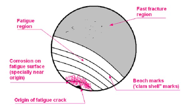
Fatigue failures occur due to cyclic loading; the mechanism of failure is the initiation and propagation of cracks. When a crack has reached a critical length, final fast fracture will occur by either Brittle Fracture or Ductile Fracture. Fatigue fracture surfaces can usually be recognized because they have one or more of the following features (see also Figure 14):
- a relatively flat, smooth region where fatigue crack growth took place, and a rougher, fast fracture region;
- lines on the fracture surface, known as “beach marks” or “clam shell marks“, which lie parallel to the crack front, perpendicular to the direction of crack growth;
- corrosion (e. g. rusting) on the fatigue region of the fracture surface if the crack has been exposed to a source of corrosion during growth. This can be increased by fretting action if compressive stresses are involved;
- wear on the fatigue region surface if compressive stresses are involved, causing the two surfaces of the crack to rub together.
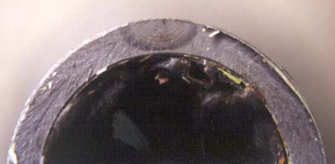
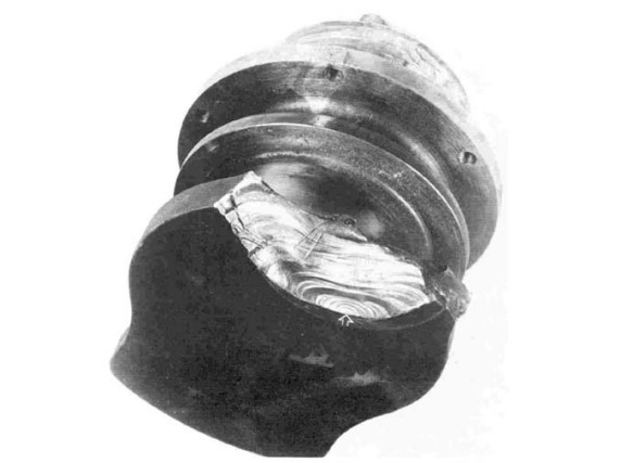
The following Figures 15 and 16 show examples of fatigue failures, illustrating these features:
The SEM photograph at Figure 17 is typical of a fatigue fracture surface. The failure is usually ductile in appearance (i. e. it does not show cleavage facets) but the scale of the ductility is small – not sufficient to create dimples as in Ductile Failure.
This type of fracture surface is quite difficult to recognize; the main thing to remember is that it does not show the features, which are typical of fast fracture, i. e. Ductile Fracture or Brittle Fracture. In some cases – usually very ductile metals such as aluminum, a pattern of parallel lines known as “striations” occurs, marking the position of the crack front on successive load cycles, as shown in Figure 18.
The total width of this SEM picture is only 12 µm (0,012 mm). This specimen was cycled with alternating blocks of 10 cycles at high stress followed by 10 cycles at low stress, creating groups of striations with two different spacings.
If striations like this are observed, then it is definitely a fatigue failure, but in many materials these striations don’t occur.
Creep Fracture
Creep failure is essentially plastic deformation, so its appearance is often similar to that of Ductile Fracture. Creep would be suspected if a component shows extensive plastic deformation before failure and if the material is operating at a temperature within its creep range, which is usually about 0,3 of its melting point (in degrees K). As with fatigue, the final failure may be ductile (by growth of voids) or brittle (by crack propagation).
Creep failures are usually of the intergranular ductile type, due to the formation of voids on the grain boundaries. Failure is usually preceded by a lot of microscopic damage, which can be seen on polished sections as shown in the two photos of Figure 19. This damage takes the form of voids (shown on the left) and/or small cracks (on the right), mostly located on the grain boundaries.
Stress Corrosion Cracking
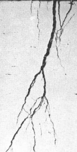
Stress-corrosion cracking (SCC), also called Environmentally Assisted Cracking, is a process of crack initiation and growth, which occurs in the presence of a corrosive environment; it can occur even if the stress is constant. If the stress is cyclic a related phenomenon called “Corrosion Fatigue” may happened. Many different mechanisms are involved and this type of failure may be difficult to distinguish from other types, but some clues to the existence of a SCC failure are:
- Multiple crack initiation and crack branching, as shown in Figure 20.
- Corrosion, which is present on the fracture surface even when the rest of the part is uncorroded.
- Intergranular fracture.
Wear Failure
Wear causes loss of material from the surface as a result of rubbing contact with another surface. This may cause failure directly, as when an engine part can no longer function, or it may contribute to other types of failure such as fatigue.
Stability Analysis
ABS Analysis
ABS reviews the stability of the proposed construction for compliance with the applicable intact and damage stability portion of Chapter 2 of the Origin, Applicability, Requirement of IMO Gas CodeIGC Code when so requested. ABS is authorized by many Administrations worldwide to review stability on their behalf.
If the vessel is to be registered in a country for, which ABS is not authorized to review stability for certification according to IGC Code, the Stability Requirements may be considered satisfied, insofar as classification is concerned, when the vessel is issued an International Certificate of Fitness for the Carriage of Liquefied Gases in Bulk by or on behalf of the Administration Registry.
Regardless of authority to act on behalf of an administration, upon client’s request ABS is prepared to provide a “consultative” review of vessel stability according to the Load Line Conventions and IMO Circulars pertaining to stability and to issue a “Statement of Fact” letter of compliance.
Intact Stability
Intact stability is the ability of an intact ship to return to its original position after being inclined due to either external or internal forces. The intact stability of the ship in all seagoing conditions, and during loading and unloading, complies with acceptable recognized standards by the country of registry.
Damage Stability
Damage stability is the ability of the ship to remain afloat and stable after damage. For LNG carriers the basic requirements for the extent of damage and ship survivability are stated in the IGC Code.
a) STANDARD OF DAMAGE
The ship should be capable of surviving the extent of damage noted discussed under Module 3. These requirements amount to a minimum of a two-compartment standard of sub-division with relaxation in way of the engine room depending upon the ship length.
b) DAMAGE STABILITY INVESTIGATION
The damage stability is to be investigated for all anticipated loading conditions, departure and arrival. Where the cargo tanks are located within the extent of the assumed damage, under the IGC, the stability is investigated assuming the cargo tanks damaged or undamaged.
The basic design requirements necessary for the carriage of LNG and protection from penetration results in a number of special damage resistant features built into the LNG carriers. These are:
- The ships have a double bottom extending for the full length of the cargo area. The depth of the double bottom generally exceeds the assumed vertical extent of the damage under the IGC.
- The ships have a double hull in the form of outboard wing tanks extending for the full length of the cargo area.
- The double hull construction results in a hull structure with a large margin of structural strength and resistance.
- The ships have a high operating freeboard and thus a large reserve buoyancy.