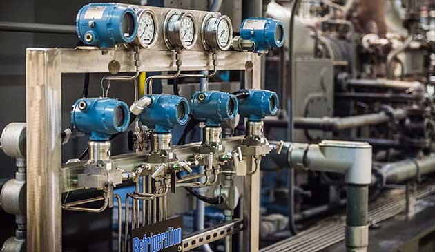
Each cargo tank is to be provided with tank instrumentation to show pressure and temperature of the cargo. Pressure gauges and temperature indicating devices shall be installed in the liquid and vapour piping systems, in cargo refrigerating installations and in the inert gas system as detailed in this article.
Cargo Tank Instrumentation
Where a secondary barrier is required, permanently installed instrumentation shall be provided to detect when the primary barrier fails to be liquid-tight at any location or when liquid cargo is in contact with the secondary barrier at any location. This tank instrumentation shall be appropriate gas detecting devices according to “Gas detection requirements “. However, the tank instrumentation need not be capable of locating the area where liquid cargo leaks through the primary barrier or where liquid cargo is in contact with the secondary barrier.
Upon special approval appropriate temperature indicating devices may be accepted by the Society instead of gas detecting devices when the cargo temperature is not lower than -55 °C.
If the loading and unloading of the ship is performed by means of remotely controlled valves and pumps, all controls and indicators associated with a given cargo tank shall be concentrated in one control position.
Tank instruments are to be tested to ensure reliability in the working conditions and recalibrated at regular intervals. Testing procedures for tank instruments and the intervals between recalibration are to be approved by the Society.
Level indicators for cargo tanks
Each cargo tank shall be fitted with at least one liquid level gauging device, designed to operate at pressures not less than the MARVS of the cargo tank and at temperatures within the cargo operating temperature range. Where only one liquid level gauge is fitted it is to be arranged so that any necessary maintenance can be carried out while the cargo tank is in service.
In order to assess whether or not one level gauge is acceptable in relation to above “any necessary maintenance” means that any part of the level gauge can be overhauled while the cargo tank is in service.
Cargo tank liquid level gauges shall be of the following types subject to any special requirement for particular cargoes shown in column “g” in the table of “Minimum requirements”Summary of Minimum Requirements for LNG and LPG tankers:
- indirect devices, which determine the amount of cargo by means such as weighing or pipe flow meters;
- closed devices, which do not penetrate the cargo tank, such as devices using radio-isotopes or ultrasonic devices;
- closed devices, which penetrate the cargo tank, but which form part of a closed system and keep the cargo from being released, such as float type systems, electronic probes, magnetic probes and bubble tube indicators. If a closed gauging device is not mounted directly on the tank it is to be provided with a shut-off valve located as close as possible to the tank;
- restricted devices, which penetrate the tank and when in use permit a small quantity of cargo vapour or liquid to escape to the atmosphere, such as fixed tube and slip tube gauges. When not in use, the devices shall be kept completely closed. The design and installation must ensure that no dangerous escape of cargo can take place when opening the device. Such gauging devices shall be so designed that the maximum opening does not exceed 1,5 mm diameter or equivalent area, unless the device is provided with an excess flow valve.
Sighting ports with a suitable protective cover and situated above the liquid level with an internal scale may be allowed by the Society as a secondary means of gauging for cargo tanks which are designed for a design vapour pressure Po not higher than 0,7 bar.
Tubular gauge glasses shall not be fitted. Gauge glasses of the robust type as fitted on high pressure boilers and fitted with excess flow valves may be allowed by the Society for deck tanks, subject to any provisions of “Special requirements”Special Requirements for LNG and LPG gas carriers.
Overflow control
Except as provided below, each cargo tank is to be fitted with a high liquid level alarm operating independently of other liquid level indicators and giving an audible and visual warning when activated. Another sensor operating independently of the high liquid level alarm is to automatically actuate a shut-off in a manner which will both avoid excessive liquid pressure in the loading line and prevent the tank from becoming liquid full.
The emergency shutdown valve referred to in “Piping System of pressure vessels on gas tankers”Cargo system valving requirements may be used for this purpose. If another valve is used for this purpose, the same information as referred to in “Piping System of pressure vessels on gas tankers”Cargo system valving requirements shall be available on board. During loading, whenever the use of these valves may possibly create a potential excess pressure surge in the loading system, BKI and the Port State Authority may agree to alternative arrangements such as limiting the loading rate, etc.
The closing time of the closing valve is to be changeable.
The sensor for automatic closing of the loading valve for overflow control as required above may be combined with the liquid level indicators required by “Level indicators for cargo tanks”.
A high liquid level alarm and automatic shut- off of cargo tank filling need not be required when the cargo tank:
- is a pressure tank with a volume not more than 200 m3;
- or is designed to withstand the maximum possible pressure during the loading operation and such pressure is below that of the start-to-discharge pressure of the cargo tank relief valve.
Electrical circuits, if any, of level alarms are to be capable of being tested prior to loading.
Pressure gauges
The vapour space of each cargo tank is to be provided with a pressure gauge which shall incorporate an indicator in the cargo control position as required above. In addition, a high pressure alarm and, if vacuum protection is required, a low pressure alarm, are to be provided on the navigating bridge and at the cargo control position. Maximum and minimum allowable pressures are to be marked on the indicators. For cargo tanks fitted with pressure relief valves, which can be set at more than one set pressure in accordance with “Cargo Temperature Control and Cargo Vent Systems”Pressure relief systems, high pressure alarms are to be provided for each set pressure.
Common read-outs of the pressure sensors on the bridge are acceptable. Each cargo pump discharge line and each liquid and vapour cargo manifold is to be provided with at least one pressure gauge. Local reading manifold pressure gauges are to be provided to indicate the pressure between stop valves and hose connections to the shore.
Hold spaces and inter barrier spaces without open connection to the atmosphere are to be provided with pressure gauges.
Temperature indicating devices
Each cargo tank is to be provided with at least two devices for indicating cargo temperatures, one placed at the bottom of the cargo tank and the second near the top of the tank, below the highest allowable liquid level. The temperature indicating devices are to be marked to show the lowest temperature for which the cargo tank has been approved by the Society.
When cargo is carried in a cargo containment system with a secondary barrier at a temperature lower than -55 °C, temperature indicating devices are to be provided within the insulation or on the hull structure adjacent to cargo containment systems. The devices shall give readings at regular intervals and, where applicable, audible warning of temperatures approaching the lowest for which the hull steel is suitable.
These alarms are to be at the cargo control position according to beginning of this article and on the navigating bridge.
If cargo is to be carried at temperatures lower than -55 °C, the cargo tank boundaries, if appropri-ate for the design of the cargo containment system, shall be fitted with temperature indicating devices as follows:
- A sufficient number of devices to establish that an unsatisfactory temperature gradient does not occur.
- On one tank a number of devices in excess of those required above in order to verify that the initial cool down procedure is satisfactory.
These devices may be either temporary or permanent. When a series of similar ships are built, the second and successive ships need not comply with the requirements of this sub-paragraph.
The number and position of temperature indicating devices shall be to the satisfaction of the Society. Common read-outs of the temperature sensors on the navigating bridge are acceptable.
Gas detection requirements
Gas detection equipment acceptable to the Society and suitable for the products to be carried shall be provided in accordance with column “f” in the table of “Minimum requirements”Summary of Minimum Requirements for LNG and LPG tankers.
In every installation, the positions of fixed sampling heads are to be determined with due regard to the density of the vapours of the products intended to be carried and the dilution resulting from compartment purging or ventilation.
Pipe runs from sampling heads shall not be lead through gas safe spaces except as permitted below. Audible and visual alarms from the gas detection equipment, if required by this article, are to be located on the navigating bridge, in the cargo control position required by this, and at the gas detector readout location.
Gas detection equipment may be located in the cargo control station required by this, on the navigating bridge or at other suitable locations. When such equipment is located in a gas safe space the following conditions shall be met:
- gas-sampling lines shall have shut-off valves or an equivalent arrangement to prevent cross-communication with gas-dangerous spaces;
- and exhaust gas from the detector is to be discharged to the atmosphere in a safe location.
Gas detection equipment is to be so designed that it may readily be tested. Testing and calibration shall be carried out at regular intervals. Suitable equipment and span gas for this purpose is to be carried on board. Where practicable, permanent connections for such equipment are to be fitted.
A permanently installed system of gas detection and audible and visual alarms shall be provided for:
- cargo pump rooms;
- cargo compressor rooms;
- motor rooms for cargo handling machinery;
- cargo control rooms unless designated as gas safe;
- other enclosed spaces in the cargo area where vapour may accumulate including hold spaces and interbarrier spaces for independent tanks other than type C;
- ventilation hoods and gas ducts where required by “Cargo LNG as fuel”Use of Cargo as Fuel on Gas Tankers;
- and air locks.
Also for hold spaces containing type C cargo tanks a permanently installed gas detection system is recommended.
The gas detection equipment shall be capable of sampling and analyzing from each sampling head location sequentially at intervals not exceeding 30 minutes, except that in the case of gas detection for the ventilation hoods and gas ducts referred to in list above sampling is to be continuous. Common sampling lines to the detection equipment shall not be fitted.
In the case of products which are toxic or toxic and flammable, the Administration may authorize the use of portable equipment except when column “i” in the table of “Minimum requirements”Summary of Minimum Requirements for LNG and LPG tankers refers to “Permanently installed toxic gas detectors”Special Requirements for LNG and LPG gas carriers for toxic detection as an alternative to a permanently installed system if used before entry of the spaces listed above by personnel and thereafter at 30 minute intervals while they remain therein.
For the spaces listed above, alarms are to be activated for flammable products when the vapour concentration reaches 30 % of the lower flammable limit.
In the case of flammable products, where cargo containment systems other than independent tanks are used, hold spaces and/or inter barrier spaces are to be provided with a permanently installed system of gas detection capable of measuring gas concentrations of 0 to 100 % by volume. The detection equipment, equipped with audible and visual alarms, shall be capable of monitoring from each sampling head location sequentially at intervals not exceeding 30 minutes.
Alarms should be activated when the vapour concentration reaches the equivalent of 30 % of the lower flammable limit in air or such other limit as may be approved by the Society in the light of particular cargo containment arrangements. Common sampling lines to the detection equipment shall not be fitted.
With reference to the requirements of paragraphs above commutation of sampling shall be carried out close to the detection cell.
In the case of toxic gases, hold spaces and/or inter barrier spaces are to be provided with a permanently installed piping system for obtaining gas samples from the spaces. Gas from these spaces shall be sampled and analysed from each sampling head location by means of fixed or portable equipment at intervals not exceeding 4 hours and in any event before personnel enter the space and at 30 minute intervals whilst they remain therein.
Every ship should be provided with at least two sets of portable gas detection equipment accept-able to the Administration and suitable for the products to be carried.
A suitable instrument for the measurement of oxygen levels in inert atmospheres is to be provided.