Petroleum as produced from a reservoir is a complex mixture of hundreds of different compounds of hydrogen and carbon, all with different densities, vapor pressures, and other physical characteristics.
A typical well stream is a high-velocity, turbulent, constantly expanding mixture of gases and hydrocarbon liquids, intimately mixed with water vapor, free water, solids, and other contaminants. As it flows from the hot, high-pressure petroleum reservoir, the well stream undergoes continuous pressure and temperature reduction. Gases evolve from the liquids, water vapor condenses, and some of the well stream changes in character from liquid to bubbles, mist, and free gas. The high-velocity gas is carrying liquid droplets, and the liquid is carrying gas bubbles.
Stated simply, field processing is required to remove undesirable components and to separate the well stream into salable gas and petroleum liquids, recovering the maximum amounts of each at the lowest possible overall cost. Field processing of natural gas actually consists of four basic processes:
- Separation of the gas from free liquids such as crude oil, hydrocarbon condensate, water, and entrained solids.
- Processing the gas to remove condensable and recoverable hydrocarbon vapors.
- Processing the gas to remove condensable water vapor, which under certain conditions might cause hydrate formation.
- Processing the gas to remove other undesirable components, such as hydrogen sulfide or carbon dioxide.
Some of these processes are accomplished in the field, but in some cases, the gas goes to a plant facility for further processing. The discussion in this section is divided into two categories, field treatment and plant operations.
Field Treatment of Natural Gas
Separation of well-stream gas from free liquids is by far the most common of all field-processing operations and, at the same time, one of the most critical. A properly designed separator will provide a clean separation of free gases from the free hydrocarbon liquids. A well-stream separator must perform the following:
- Cause a primary-phase separation of the mostly liquid hydrocarbons from those that are mostly gas;
- Refine the primary separation by removing most of the entrained liquid mist from the gas;
- Further refine the separation by removing the entrained gas from the liquid, and;
- Discharge the separated gas and liquid from the vessel and ensure that no re-entrainment of one into the other occurs.
If these functions are to be accomplished, the basic separator design must:
- Control and dissipate the energy of the well stream as it enters the separator;
- Ensure that the gas and liquid velocities are low enough so that gravity segregation and vapor-liquid equilibrium can occur;
- Minimize turbulence in the gas section of the separator and reduce velocity;
- Control the accumulation of froths and foams in the vessel;
- Eliminate re-entrainment of the separated gas and liquid;
- Provide an outlet for gases, with suitable controls to maintain preset operating pressure;
- Provide outlets for liquids, with suitable liquid-level controls;
- If necessary, provide clean out ports at points where solids may accumulate;
- Provide relief for excessive pressures in case the gas or liquid outlets should be plugged, and;
- Provide equipment (pressure gages, thermometers, and liquid-level gage-glass assemblies) to check visually for proper operation.
The process equipment and conditions downstream of a separator will usually dictate the necessary degree of separation and the actual vessel design. Ideally, gases and liquids should come to full equilibrium in the separator, but a compromise must usually be made between the degree of separation achieved and cost of the installation.
The following factors must be considered in sizing and selecting a separator.
- Liquid flow rate (oil and water), barrels per day and minimum and peak instantaneous.
- Gas flow rate, million standard cubic feet (MMscf) per day.
- Specific gravities of oil, water and gas.
- Required retention time of fluids within the separator; retention time is a function of physical properties of the fluids.
- Temperature and pressure at which the separator will operate and design pressure of the vessel.
- Whether the separator is to be two phase, such as liquid and gas, or three phase-that is, oil, water, and gas.
- Whether or not there are solid impurities, such as sand or paraffin.
- Whether or not there are foaming tendencies.
Types of Separators
Three basic types of separators are widely used for gas-liquid separation:
- Vertical (Pic. 1);
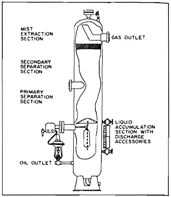
Pic. 1 Typical vertical oil and gas separator with mist extractor - Horizontal (Pic. 2), and;
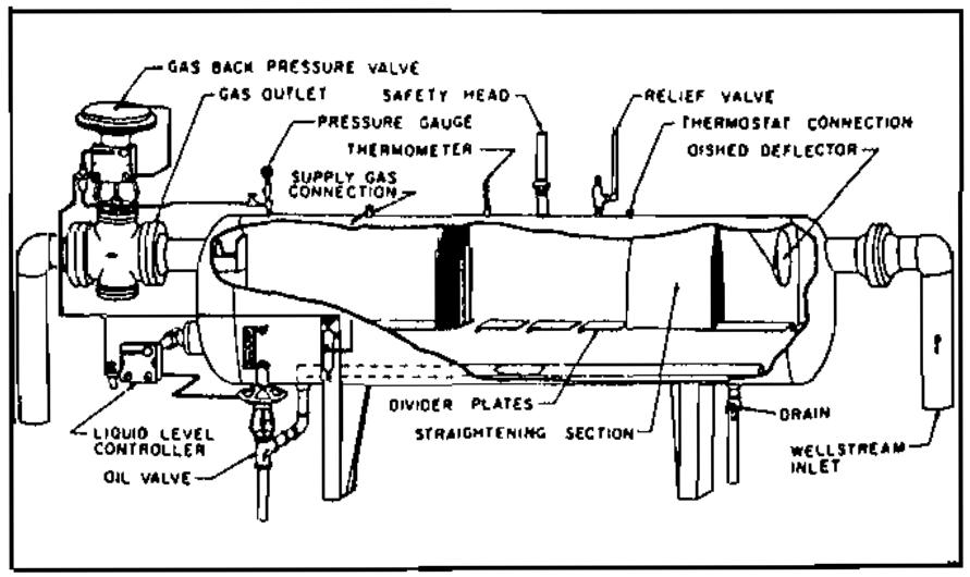

Pic. 2 High pressure horizontal oil and gas separator - Horizontal double-barrel (Pic. 3).


Pic. 3 Double-tube horizontal oil and gas separator
Each has specific advantages, and selection is usually based on which one will accomplish the desired results at the lowest cost.
A vertical separator is often used on low to intermediate gas-oil ratio well streams and where relatively large slugs of liquid are expected. It can be fitted with a false cone bottom to handle sand production. A vertical separator occupies less floor space, an important consideration where this might be expensive as on an offshore platform. However, because the natural upward flow of gas in a vertical vessel opposes the falling droplets of liquid, a vertical separator for the same capacity may be larger and more expensive than a horizontal unit. In operation, an inlet diverter spreads the inlet fluids against the vertical separator shell in a thin film and at the same time imparts a centrifugal motion to the fluids. This provides the desired momentum reduction and allows the gas to escape from the thin oil film. The gas rises to the top of the vessel, and the liquids fall to the bottom. Some small liquid particles will be swept upward with the rising gas stream, and these particles are separated by a centrifugal baffle arrangement below the gas-outlet connection.
The horizontal separator may be the most economical. It may be less expensive than the vertical separator of equal capacity. The horizontal separator has a much greater gas-liquid interface area consisting of a large, long, baffled gas-separation section. Horizontal separators are almost always used for high gas-oil ratio well streams, for foaming well streams, or for liquid-from-liquid separators. A horizontal separator is easier to install, service, and transport. Several separators can be stacked easily into stage-separation assemblies minimizing space requirements. In a horizontal separator, gas flows horizontally and, at the same time, falls toward the liquid surface. Some separators have closely spaced horizontal baffle plates that extend lengthwise down the vessel upon which baffle plates are evenly spaced at a 45° angle to the horizontal. The gas flows in the baffle surfaces and forms a liquid film that is drained away to the liquid section of the separator. The baffles need only be longer than the distance of liquid trajectory travel at the design gas velocity.
Some separators use knitted wire-mesh pads, 4 to 8 in. thick, across the gas section of the separator or across the gas-outlet nozzle. Wire mesh can provide good gas-liquid separation but may be plugged by paraffin or solids in the gas stream. Wire-mesh pads should not be used unless the well stream is so clean that no danger of plugging exists.
A double-barrel horizontal separator has all the advantages of a normal horizontal separator plus a much higher liquid capacity. Incoming free liquid is immediately drained away from the upper section into the lower section. The upper section is filled with baffles, and gas flow is straight through and at higher velocities.
A horizontal three-phase separator (Pic. 4) is designed to separate oil, water, and gas and has two liquid outlets.
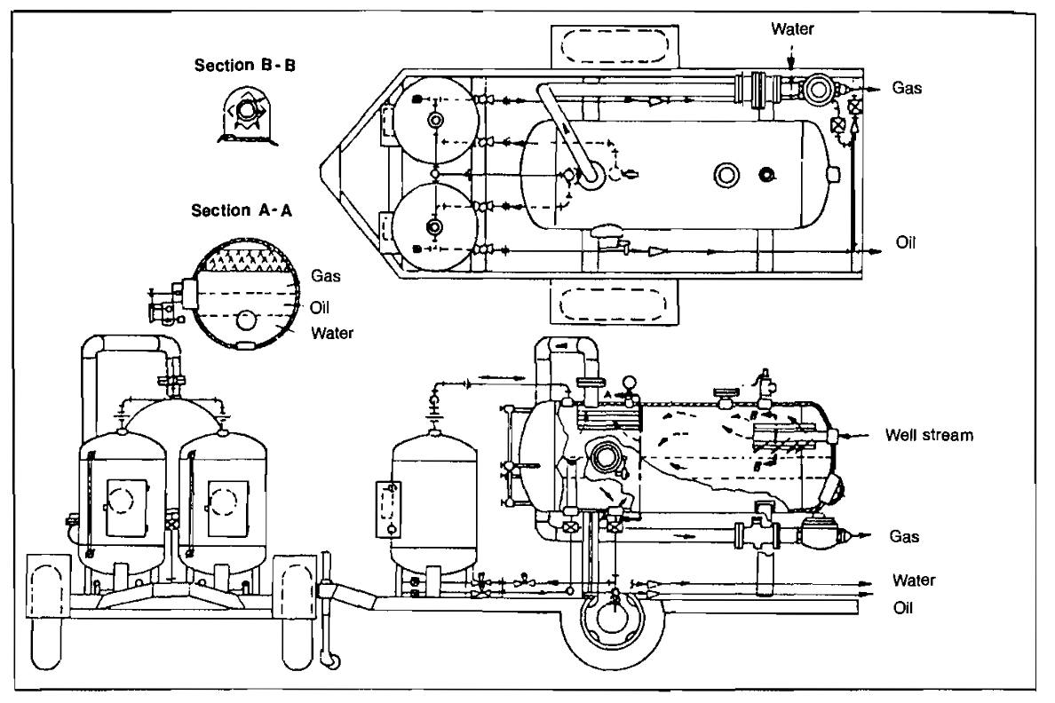
Three-phase separators are used commonly for well testing and in instances where free water readily separates from the oil or condensate. They are identical to two-phase vessels except for the water compartment, an extra level control, and dump valve.
Filter separators (Pic. 5) are designed to remove small liquid and/or solid particles from gas streams.
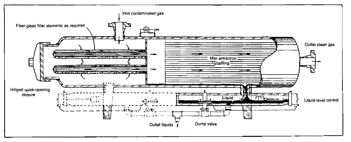
These units were designed specifically to handle those applications where, due to the extremely small particle size, conventional separation techniques employing gravitational or centrifugal force are ineffective. Contaminants of this small size can be removed most effectively by passing the gas through a fine, high-quality filtering medium. Several conurations of filter separators are used, depending upon the required efficiency and on whether liquids or solids, or both, are to be removed. Some filter elements have collection efficiencies of 98 % of the 1-micron particles and 100 % of the 5-micron particles when operated at rated capacity and recommended filter-change intervals. A typical filter separator for removing both liquid and solid contaminants is shown in Picture 5.
Separator Controls
Liquid level within the separator must be maintained within reasonable limits to prevent discharging liquid out of the gas line or gas out of the liquid line and to assure proper functioning and flow through the separator internals. Pressure within the separator is usually maintained within a specific pressure range by a gas back-pressure regulating valve. Temperature within most separators is usually not controlled although there are exceptions, such as low-temperature separation systems. Safety and protection against overpressure is provided by a pressure-relief valve set at the design pressure of the separator.
Stage Separation
Stage separation is a process in which gaseous and liquid hydrocarbons are separated into vapor and liquid phases by two or more equilibrium flashes at consecutively lower pressures. As shown in Picture 6, two-stage separation involves one separator and a storage tank. Three-stage separation requires two separators and a storage tank. Four-stage separation would require three separators and a storage tank. The tank is always counted as the final stage of vapor-liquid separation because the final equilibrium flash occurs in the tank.
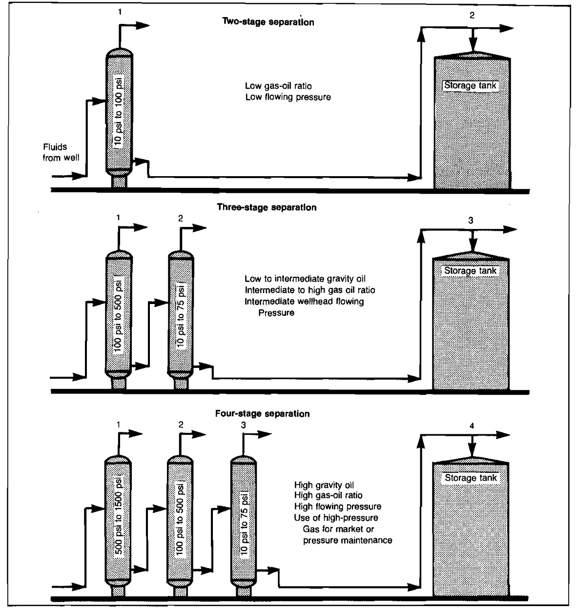
The purpose of stage separation is to reduce the pressure on the reservoir liquids gradually, in steps or stages, so that a more stable stock-tank liquid will result. Petroleum liquids at high pressures usually contain large quantities of liquefied propanes, butanes, and pentanes, which will vaporize or flash as the pressure is reduced. This flashing can cause a substantial reduction in stock-tank liquid recovery, depending upon well-stream composition, pressure, temperature, and other factors. For example, if a volatile condensate at 1 500 psig was discharged directly into an atmospheric storage tank, most of it would immediately vaporize, leaving very little liquid in the tank.
The ideal method of separation, to attain maximum liquid recovery, would be that of differential liberation of gas by means of a steady decrease in pressure from that existing in the reservoir to that existing in the storage tanks. With each tiny decrease in pressure, the gas evolved would immediately be removed from the liquid. However, carrying out this differential process would require an infinite number of separation stages, obviously an impractical solution.
Low Temperature Separation
Low temperature separation, probably the most efficient means yet devised for handling high pressure gas and condensate at the wellhead, performs the following functions:
- Separation of water and hydrocarbon liquid from the inlet well stream;
- Recovery of more liquids from the gas than can be recovered with normal temperature separators, and;
- Dehydration of gas, usually to pipeline specifications.
The first low temperature units were developed and placed in operation in 1948 to dehydrate gas at the wellhead in remote locations so that high-pressure gas and condensate could be gathered at central locations without the problems of hydrate plugging.
Essentially, the low temperature separation process is one of intentional hydrate formation and controlled melting. The inlet gas is cooled by expansion, due to pressure reduction, causing water and liquid hydrocarbons to condense; if hydrates are formed, they are quickly melted. Dry gas, condensate, and free water are then discharged from the vessel under controlled conditions. Since this separation system permits operating conditions well below hydrate-formation temperatures, the recovery of hydrocarbon liquids is much higher than that possible for conventional separation. Condensation of a higher percentage of the water vapor also is accomplished, resulting in dehydration of the gas.
Since low temperature, separation is achieved by the cooling effect of gas expansion-that is, pressure reduction across the choke-how much pressure drop is needed to obtain adequate cooling? Generally speaking, satisfactory operation and dehydration to pipeline specifications can be accomplished with a pressure differential as low as 1 000 psi, provided the temperature upstream of the choke can be controlled to near the hydrate point.
The actual minimum differential between flowing and line pressures depends primarily upon the pressure range in which the hydrate temperature falls. Noting the pressure-temperature drop chart (Pic. 7), it can be seen that a 1 500 psi drop from 3 000 psi at 120 °F will provide a final temperature of only 78 °F, while a 1 500 psi drop from 2 000 psi at 120 °F will give a final temperature of 49°F.
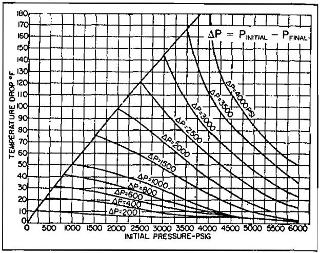
The actual temperature drop will not necessarily correspond to that shown on the chart; composition of the gas stream, flow rate, liquid rates, bath temperature, and ambient temperature will affect the actual temperature drop. Water dew points will average 10 °F to 15 °F below the indicated temperature due to the adsorptive effects of the hydrates on the vapor-phase water.
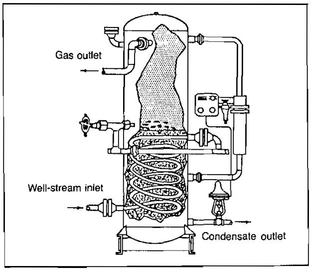
Some means must be provided to prevent formation of hydrates in the low temperature separator. This is accomplished by either piping the hot well stream through the separator, as shown in Picture 8, or by injecting hydrate inhibitors upstream of the separator.
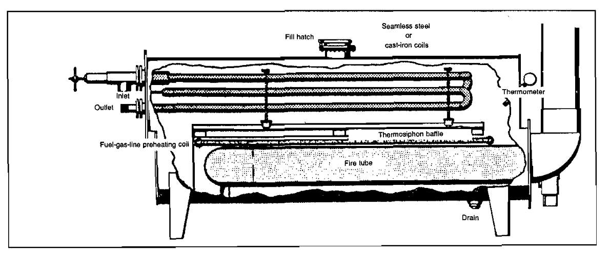
In some cases, a line heater is required upstream of the separator for the first method (Pic. 9).
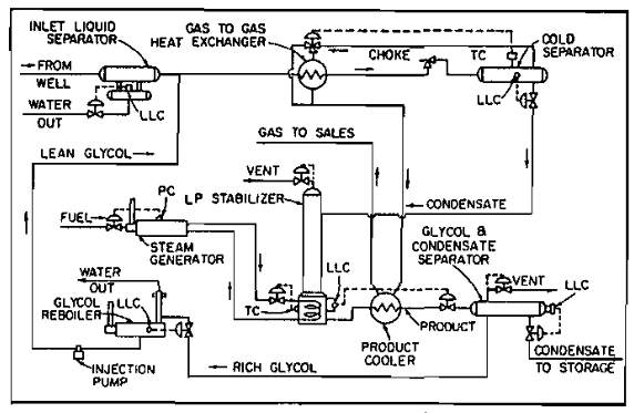
A schematic diagram of the second method, using glycol injection, is shown in Picture 10.
Condensate Stabilization
One of the problems in using low temperature separation units of both the mechanical and glycol-injection types is high stock-tank vapor loss. These losses are the result of vaporizing appreciable quantities of liquid propane and butane with dissolved methane and ethane, which are liberated when the pressure on the liquid is reduced from the low temperature separator to storage pressure. When these light ends vaporize in a stock tank, they carry some of the heavier hydrocarbons with them to be burned or lost in the atmosphere. Stabilization is a means of removing these lighter hydrocarbons from the liquid present in the bottom of the low temperature separator with a minimum loss of heavier hydrocarbons. Stabilization results in a larger volume of stock-tank liquids available for sale.
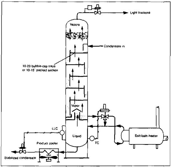
The stabilization system consists of a vertical vessel, which may be packed with ceramic rings or fitted with trays spaced from 12 to 24 in. apart inside the vessel. The liquid in the lower section of the tower is heated by an indirect heater or steam coils. The cold condensate from the bottom of the low-temperature separator flows directly to the top of the stabilizer or may flow to a flash tank prior to entering the stabilizer. From the flash tank, the gas is routed to become fuel or to be disposed of by other means, and the liquid is taken to the top of the stabilizer. Some of the light hydrocarbons are vaporized and pass from the top of this vessel to the gas-sales, fuel, or vent line. The liquid hydrocarbons flow through the packing or down the trays, absorbing some of the heavier gaseous hydrocarbons, which have been vaporized at the bottom of the vessel. At the bottom of the vessel, the heat added from the heater or reboiler vaporizes most of the lighter hydrocarbons. After being cooled, the stabilized liquid flows to storage and the lighter ends flow upward to be reabsorbed or to leave the top of the vessel (Pic. 11).
The amount of additional condensate that can be recovered by stabilization is dependent upon the pressure and temperature at which the low temperature separator is operated and the composition of the gas being processed.
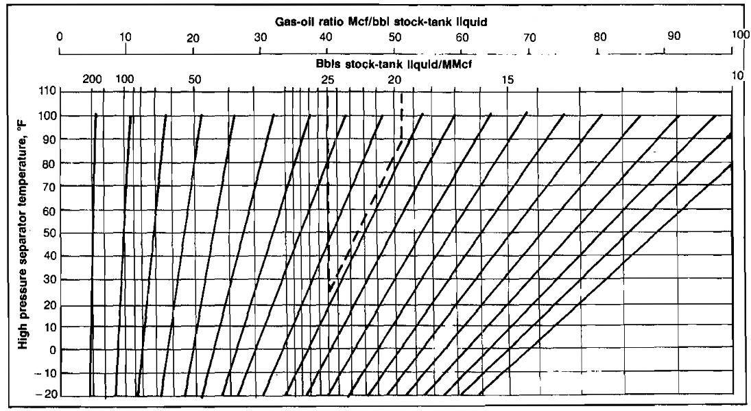
Additional hydrocarbon liquid recovery that can be gained by use of low temperature separation as compared to conventional separation depends on the exact composition of the well stream and upon the operating temperature of the low temperature separator. In the absence of an analysis, the increased recovery may be estimated by assuming that stock-tank liquid recovery will be increased about 0,5 bbl per MMscf for each 10 °F decrease in separator temperature. For example, if separation at 80 °F produces 10 bbl/MMscf, then separation at 20 °F would produce an additional 3 bbl/MMscf. An additional increase in recovery of about 10 % might be expected if the low temperature liquid was then stabilized. For richer gas streams, on the order of 50 bbl/MMscf, the increased liquid recovery would be about 0,75 bbl/MMscf for each 10 °F decrease in separator temperature. These ures are merely rules of thumb and are only an approximation of the actual increased recovery. Picture 12 illustrates the effect of separation temperature on liquid recovery.
Gas Plant Operations
Gas plants and the treatment of natural gas are very important segments of the gas production operation. Untreated or unprocessed natural gas contains many hydrocarbon compounds and a few non hydrocarbon compounds. Treating natural gas in plant facilities involves removing certain of the compounds that are of considerable value by themselves or because they are contaminants that render the gas unsuitable for sale purposes. The predominate constituent of natural gas is methane with smaller amounts of other hydrocarbons. Table 1 gives examples of a few of the common components of natural gas and their phase after processing.
| Table 1 | ||
|---|---|---|
| Component Hydrocarbons | Chemical Formula | How Utilized |
| Methane | CH4 | Fuel, gaseous state. |
| Ethane | C2H6 | Mixed with methane as gaseous fuel and alone as chemical feed stock. Exists as gas. |
| Propane | C3H6 | Liquid fuel or chemical feed stock. Pressure storage required. |
| Pentanes | C5H12 | Liquid fuel or chemical feed stock. Pressure storage required. |
| Hexanes | C6H14 | Constituents of natural gasoline. Pressure storage not required. |
| Non-Hydrocarbons | ||
| Hydrogen Sulfide (acid gas) | H2S | Poisonous gas constituent of natural gas. Removed and converted to elemental sulfur. |
| Carbon Dioxide (acid gas) | CO2 | Removed from natural gas if in excess of sales specification. |
| Nitrogen | NO2 | Ordinarily not removed. Inert gas with no heating value in natural gas. |
| Water | HO | Removed to meet sales gas water dew-point specification. |
Pentanes and hexanes are shown in the table as constituents of natural gasoline. Natural gasoline also includes liquids heavier than hexane. Butanes may also be present in natural gasoline. Natural gas containing hydrogen sulfide in concentrations sufficient to prevent it from meeting sales gas specifications is termed “sour” gas.
The gas sold to gas transmission companies usually must meet certain requirements with respect to water content, hydrocarbon dew-point, heating value, and hydrogen sulfide content. Some sort of processing plant is required to treat the gas so that the specifications in the sales contract are met.
- A dehydration plant is provided to control the water content;
- A gas processing plant of one type or another is provided to remove certain hydrocarbon components to meet hydrocarbon dew-point specifications;
- And a gas sweetening plant is required to remove acid gas (when present).
Because of environmental pollution, hydrogen sulfide cannot be flared, and is therefore converted to elemental sulfur, a marketable product.
Any given plant installation can have overlapping purposes. Oil production may be made possible or be increased; the associated gas can be conditioned for sale or other use, such as injection; the removal of liquid products can be accomplished; and the environment can be protected by converting hydrogen sulfide removed from the gas into elemental sulfur, all within the same plant.
The removal of the heavier hydrocarbon components as liquid products is accomplished in gas processing facilities by the use of simple physical principles. Gas and liquid or two liquids of different densities are separated by passing them through a vessel large enough for them to decelerate and have time to separate. Hydrocarbons can be condensed and separated as liquids by increasing the pressure and reducing the temperature. They can also be separated by absorbing them in oil, cryogenically separating them, or adsorbing them on a desiccant. Water can be removed by adsorbing it on a desiccant, absorbing it in glycol, or by chilling the gas. Hydrogen sulfide and carbon dioxide can be removed by chemically reacting them with a chemical solution, adsorbing them on a desiccant, or absorbing them in a physical solvent.
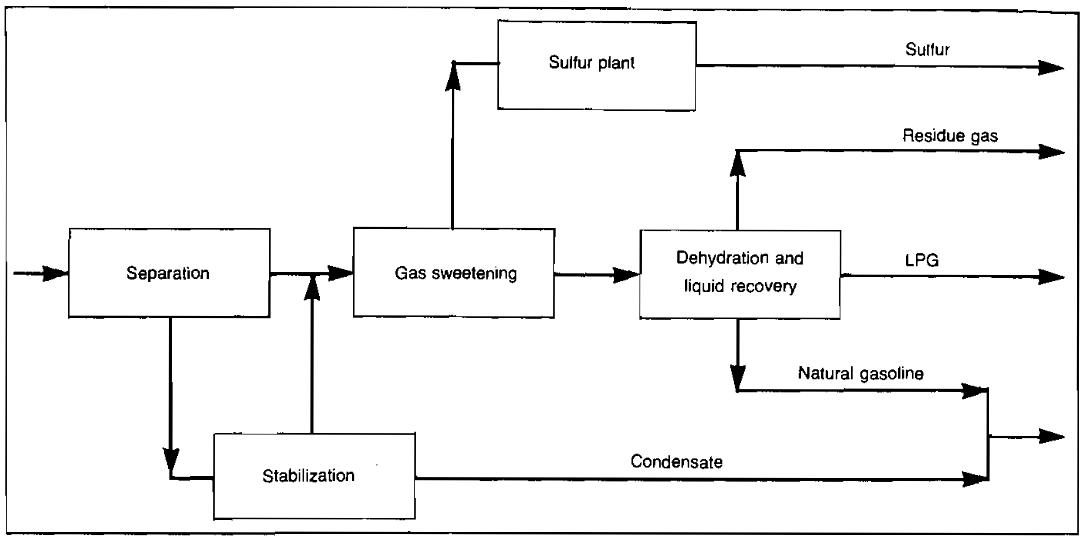
Gas processing is simply various combinations of these basic processes. With the necessary piping and equipment to provide heat, cooling, heat exchange, and to contact and separate the streams as they are processed, these processes become the gas plant. A typical combination of processes to form a gas plant is shown in Picture 13.
The following discussion treats in more detail the methods for processing natural gas.
Liquid Hydrocarbon Recovery
The following discussion relates only to the broad subject of the use of gas processing plants for recovery of the ethane and heavier hydrocarbons from a gas stream. Such a plant may process the gas associated with oil production, in which case it is known as a casing-head plant. Usually the casing-head gas contains a larger amount of recoverable liquid hydrocarbons than non-associated gas. Gas from gas reservoirs may also serve as feed to a gas processing plant. Anyone of several methods of recovering liquid products from gas may be used to process gas regardless of its source. Products extracted from the gas in liquid recovery processes may include ethane, propane, isobutane and normal butane, and natural gasoline. These products may be fractionated at the plant or leave the plant as a single liquid mixture to be separated elsewhere.
Compression Processing. One type of casing-head gas processing plant is shown schematically in Picture 14.
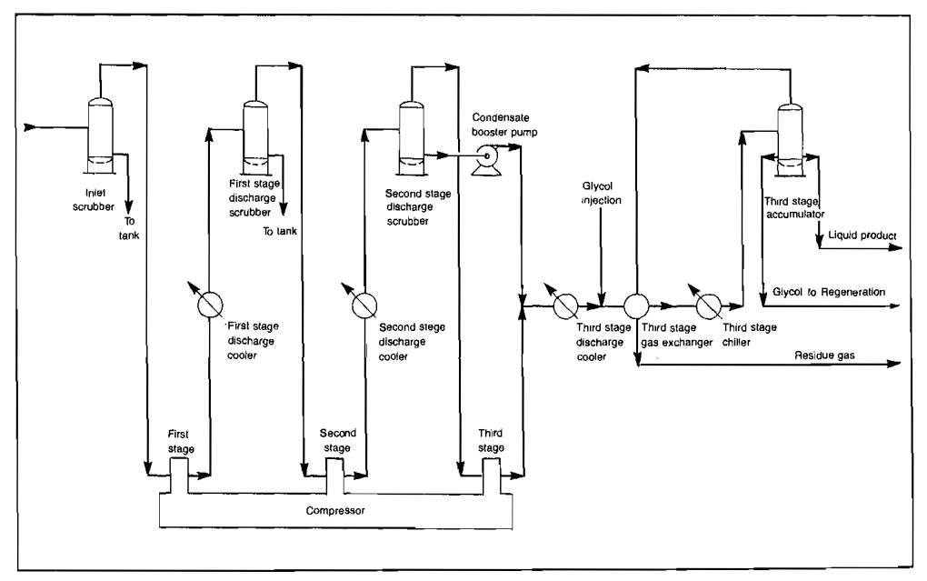
The gas may arrive at the plant inlet at very low pressure, 5 psig or even less being common. The gas enters the inlet scrubber where any liquids are removed. The end use of such gas usually requires it to be at a final pressure of 500-900 psig, and accordingly, it will ordinarily be compressed through three stages of compression. Gas compressor equipment is discussed in detail in Usage of Natural Gas Compressors in the Gas Production Operations“Types and Design of the Natural Gas Compressors”. The compressed gas is cooled between compressor stages to conserve horsepower and to keep the compressor discharge temperatures within reasonable limits. Either forced air coolers or heat exchangers using water as the cooling medium may be used. Liquids may be condensed between stages depending upon the richness of the gas, its temperature, and pressure.
In a plant such as shown in Picture 14, water vapor in the gas condenses as the pressure is increased and the gas cooled. If liquid is formed in any of the coolers, either water or hydrocarbon, then the gas leaving is at its dew point with respect to either water or hydrocarbon, or both. Gas hydrates may cause trouble under these conditions even though dew points are far above freezing. The liquid product from a compression gas processing plant will have a very high vapor pressure and will therefore be difficult and expensive to store without stabilizing the liquid product or taking substantial vapor losses.
Absorption Processing. If economics warrant increasing the recovery of the marketable products, or if gas sales dew point specifications require removal of more of the heavier hydrocarbons, the more complex and expensive absorption process is used in the gas processing plant. Absorption involves contacting the compressed raw gas with a liquid hydrocarbon called lean oil or absorption oil in an absorber where components in the gas dissolve in the lean oil. The heavier components dissolve more easily, and the oil will hold more of them than the lighter components, but some of the lighter components are absorbed also. The bulk of the gas, called residue gas, leaves the top of the absorber while the absorbed components leave with the rich oil from the bottom of the absorber.
The absorption oil process can be carried out at ambient temperatures or process temperatures may be lowered by refrigeration. Although ambient temperature plants are now generally considered obsolete, the design of these older casing-head processing plants usually does not lend itself to economic modification to the modern, more efficient types. However, this operation can be optimized by adjusting process variables.
A flow-sheet of a refrigerated light oil absorption gas process is shown in Picture 15.

The feed gas enters the gas-gas exchanger that serves to recover refrigeration from the plant residue gas stream. The gas then passes through the gas chiller, which is often cooled by vaporizing liquid propane from a mechanical refrigeration system. The cooled gas from the chiller then passes to the absorber. In this type of plant, the lean oil is not pumped directly to the absorber proper, but to a presaturator chiller where the gas from the top of the absorber is mixed with the stripped lean oil. The effluent from the presaturator chiller enters a separator tank from which the separated gas flows to the gas-gas exchanger. The liquid from the presaturator separator is then pumped to the top tray of the absorber. The lean oil is thus saturated with methane and ethane at the chiller temperature before entering the absorber. This minimizes the temperature rise from dissolving gas in the absorber and permits higher absorption of propane.
The rich oil from the bottom of the absorber flows to the rich oil flash tank where some of the undesirable materials picked up in the absorber, particularly methane, are flashed off at a lower pressure. Because of the adiabatic expansion, fluids in the rich oil flash tank will usually be considerably colder than the absorber bottoms. The vapors from the rich oil flash tank are recycled back to the plant inlet after compression and cooling. The cold liquid from the flash enters the lean oil/ rich oil exchanger, which conserves refrigeration by further cooling the lean oil from the air-cooled lean oil cooler. Some flashing of the rich oil occurs as the temperature is increased in the exchanger. The mixture is fed to the center section of the rich oil de-ethanizer.
The rich oil de-ethanizer column usually has a larger diameter lower (stripping) section and a smaller diameter top absorption section, the two diameters reflecting the column loadings. Heat enters the column through the reboiler and the side heater. The top (reabsorber) section serves as an absorber where desirable components are dissolved in the lean oil and are washed downward. The reabsorber section is supplied with cold lean oil from the lean oil-rich oil exchanger. The lean oil flow and the bottom temperature determine the amount of propane retained and limit the ethane in the propane as required to meet propane specifications. This same type of column is called a rich oil demethanizer if ethane is being recovered. The overhead product from such columns is gaseous and usually serves as a source of plant fuel gas with any excess going to the recycle recompressor.
The hot rich oil leaves the bottom of the de-ethanizer and moves to the lean oil still where absorbed products are separated from the lean oil. Again, as in the case of the rich oil de-ethanizer, a two-diameter column is used because of the difference in loads between the top and bottom of the column. To supply the necessary stripping vapors in the still, the major part of the still bottoms is pumped to the furnace reboiler. The net lean oil bottom required by the absorption process is withdrawn and returns through the heat exchangers connected to the rich oil de-ethanizer, from which it flows to the lean oil cooler. The products stripped from the lean oil are taken overhead from the still and condensed. Reflux is pumped back to the column. The liquid products from this type plant are quite often sold as a mixed stream or can be fractionated in a separate plant.
Cryogenic Processing. In the previous discussion, it has been shown that relatively high ethane recovery can be achieved by the combination of low temperature and appropriate lean oil circulation in an absorption plant. Under certain circumstances, it has become economic to process gas for high ethane recovery using only extremely low temperatures. at moderate pressure. Such plants are in the cryogenic category and have become practical and economic in the natural gas processing industry with the development of the turbine type expander-compressor. This type of process is most appropriate where high pressure gas is available and the end use of the gas is at a low pressure and relatively close to the processing point
A flow-sheet of the process is shown in Picture 16.
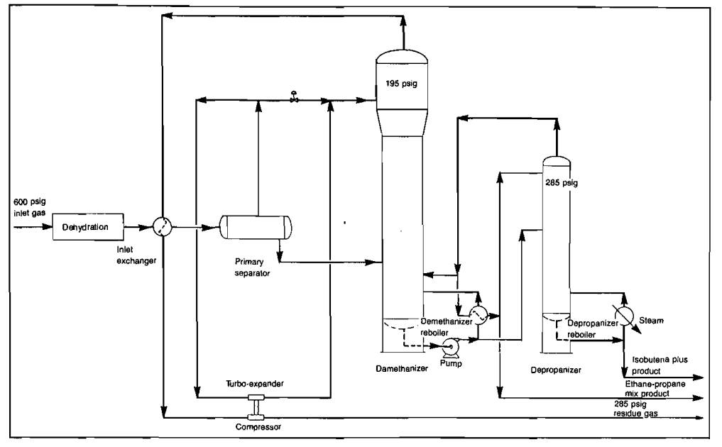
The dehydrated plant feed enters the gas-gas exchanger where, by exchange with the plant residue, the feed temperature is lowered to 80 °F. Even with a relatively dry gas, some liquid hydrocarbons will condense at these conditions. The liquid is separated and fed to the demethanizer. The vapor proceeds to the turbine exhaust temperature at about -150 °F. The exhaust is a liquid vapor mixture at these conditions and enters as feed at the top of the unrefluxed demethanizer. The turbine expander, a very high-speed device rotating at speeds up to 25 000 RPM, is directly connected to the centrifugal compressor. Plants such as this normally recover 30-60 % of the ethane entering in the plant feed stream.
Adsorption Processing. Hydrocarbon recovery by adsorption is another method that becomes economic under certain conditions. This process depends upon the ability of certain solid materials to adsorb gases or liquids. Materials that have the necessary properties for adsorption due to their large surface area of minute pores are activated carbon, bauxite, activated alumina, silica gel, and synthetic zeolites called molecular sieves. Hydrocarbon recovery units using these materials also remove water vapor from the gas stream.
Solid bed adsorption is a cyclic batch type operation that operates continuously by the use of two (or more) adsorption towers as shown in Picture 17.
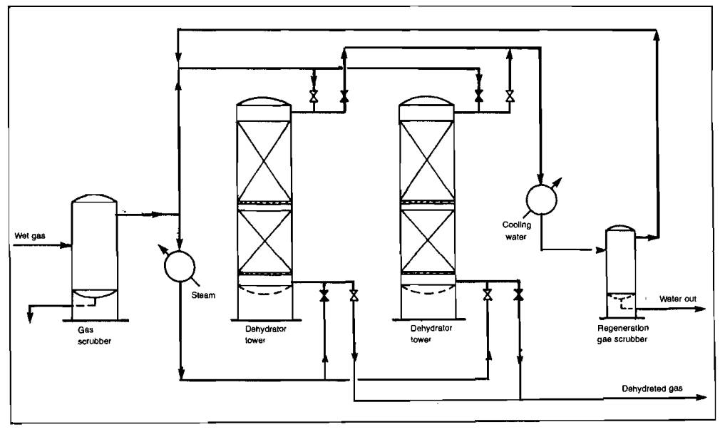
While one tower is on a drying cycle, the other tower is being regenerated by heating the desiccant with hot gas that vaporizes the adsorbed hydrocarbons and water. The hot regeneration gas containing the hydrocarbons and water vapor is cooled, condensing out most of the water and hydrocarbons that are drained from the system, and the regeneration gas returns to the wet, main gas stream.
In a large system, the towers may contain several tons of desiccant. Switching of the gas flow through the beds and control of the cycles is usually automatic. The hydrocarbon recovery units are also called fast cycle adsorption units because the cycles are quite short, 20 to 40 minutes. The cycle length is related to the hydrocarbons to be adsorbed and to the desiccant properties. Product recoveries are quite low, usually 70 to 90 % of the pentanes and heavier. However, this same principle is used in a process marketed by one company in which an appreciable amount of ethane recovery is achieved. Units using this company’s process are reported to be comparable to an adsorption gas processing plant in respect to recovery efficiencies and investment. However, most hydrocarbon recovery units are applicable only to rather dry gases, and are often used where a minimum investment for relatively small gas volumes and short life are involved.
Gas Dehydration
There are three common methods by which water vapor is removed from natural gas. These involve the use of either a solid desiccant, a liquid desiccant, or refrigeration. Solid desiccant dehydration, as in adsorption hydrocarbon recovery, depends upon the adsorption of water on bauxite, activated alumina, silica gel, or molecular sieves. For dehydration, the cycles may be up to 24 hours, and the water being more strongly adsorbed displaces most of the hydrocarbons that were adsorbed. Some hydrocarbon liquid is recovered with the condensed water. Solid desiccant dehydration can produce essentially totally dry gas and is required for the feed gas for the cryogenic type gas processing plant.
Liquid desiccant dehydration of gas uses a continuous contacting process with a very concentrated solution of triethylene glycol usually serving as the desiccant. A typical flow scheme of such a plant is shown in Picture 18.

While liquid desiccant dehydration does not produce a totally dry gas, it can be used for almost all gas dehydration except that required for cryogenic plants. As shown by the flow diagram, gas enters the absorber, which is a trayed tower, and passes upward countercurrent to the glycol flowing downward. The water is absorbed by the glycol and leaves with it from the bottom of the absorber. The water-rich glycol flows to the regenerator where the water is stripped out by heat.
The water leaves the system as steam from the top of the column. In some units, stripping gas is introduced into the column to effect a more complete removal of water. The amount of water removed and the dew point depression achieved are governed by the concentration of regenerated glycol, the glycol flow rate, the number of contact trays in the absorber column, and the temperature of the incoming gas. Dew point depressions of 100 °F are common and, with careful design, depressions of 150 °F can be achieved. Liquid desiccant dehydrators are used extensively with the low temperature absorption type gas processing plants and for field locations since they normally require little attention.
Dehydration by chilling the gas is accomplished in many plants in which hydrocarbon recovery is achieved by either condensation or low temperature absorption. Removal of water vapor by this method requires that the formation of hydrates and ice be prevented during the condensation and removal of the water from the system. This is achieved by injecting a solution of ethylene glycol into the gas stream being chilled. The resultant mixture of cold gas, water-glycol solution, and condensed hydrocarbons, if any, then pass to a tank where the glycol solution that includes the condensed water settles out in the lower layer and is drained from the tank. The water-rich glycol solution is regenerated in equipment similar to that used in a glycol dehydration unit. However, in this unit, regeneration of the glycol is usually limited to about an 85 % solution and the flow is adjusted so that the water absorbed dilutes it to about a 75 % solution.
Gas Sweetening
Many natural gases available for processing or for sale are termed “sour” because they contain hydrogen sulfide, which is an extremely poisonous gas. Gas sales contracts usually limit the amount of this compound to about 0,25 grains per hundred cubic feet (about four parts per million). If hydrogen sulfide is present in large amounts, it is removed by a sweetening unit of the type shown schematically in Picture 19.

The chemicals used to remove hydrogen sulfide in this unit also remove carbon dioxide. Both gases are identified by the general term of acid gas.
One of the most commonly used materials for the removal of the acid gases is a water solution of monoethanolamine (MEA). Other common chemicals used to remove acid gases are diethanolamine (DEA) and Sulfinol, which is a mixture of sulfolane, di-isopropanolamine, and water. The first two chemicals remove acid gases by chemical reaction, while Sulfinol works on the basis of chemical reaction plus physical absorption. There are other sweetening processes used commercially, and the flow schemes are all much the same; however, the three mentioned are those most widely used for the removal of acid gas.
Referring to Picture 19, the sour natural gas enters the bottom of the contactor and moves upward countercurrent to the flow of MEA solution. Gas meeting the required hydrogen sulfide specification leaves the top of the contactor. The rich MEA solution flows to the regenerator where, by means of heat, the acid gases are stripped from the MEA solution. The lean MEA solution is cooled by heat exchange and pumped back to the contactor. The acid gas and water vapor from the top of the regenerator pass through the acid gas cooler where most of the water vapor is condensed out and is pumped back to the regenerator as reflux. The contactor may operate at pressures from 50 psig to 1 000 psig or more, while the regenerator operates at just slightly above atmospheric pressure.
Some gases will contain only trace quantities of hydrogen sulfide, but the concentration may exceed by several times that specified under the sales gas contract. In such cases, either a material called iron sponge or molecular sieves are used to remove hydrogen sulfide. Iron sponge consists of iron oxide deposited on wood chips or shavings. The iron oxide is converted to iron sulfide in sweetening the gas and has a relatively short life. The molecular sieves are regenerated with heat just as they are in other adsorption type processes.