Discover the importance of Geometric Dilution of Precision (GDOP) in GPS technology. This article delves into how GDOP impacts positioning accuracy, the factors that contribute to its variation, and practical tips for minimizing its effects to enhance navigation and surveying precision.
Loran-C Position Determination and AccuracyEquation in this Loran-C Position Determination and Accuracyarticle of the main text enables calculation of the fix accuracy (2 drms) in terms of the bearings from the user to the master and two secondary stations, the common standard deviation of each TD, the correlation coefficient between the two TDs, and the gradient of the LOPS along the baseline.
Introduction
To recapitulate, 2 drms is the radius of the fix area with probability content of at least 95 %. That is, at the given point in the coverage area, at least 95 % of the apparent fixes would be within a circular area of radius 2 drms.
It is given by the equation:
where:
- A, B, C – angles defined in Figure 1;
- ρ – correlation coefficient between the measured TDs, generally taken to be 0,5;
- K – baseline gradient, 491,62 ft/usec, and;
- σ – common value for the standard deviation of each TD, generally taken to be 0,1 usec for accuracy calculations.
Referring to Figure 1, angle A is the angle between the first secondary and the master station (viewed from the user’s position) and angle B is that subtended by the master and the other secondary. The actual TDs are shown by the dashed lines which are bisectors of angles A and B.

The crossing angle, C, for the three station fix is:
The parameter ρ in equation (1) is the correlation coefficient between the two TDs. The three individual signals from the master and two secondaries are assumed to be independent and uncorrelated because the timing of each signal is derived from separate cesium oscillators. However, the two TDs are correlated to some degree because both are based upon a common master signal. The correlation coefficient varies throughout the coverage area, but is typically given the value 0,5 in chain coverage calculations.
Numerical Examples
In the illustration, angle A is approximately 89 degrees, and angle B is approximately 70 degrees and angle C = 8 912+7 012 = 79,5 degrees. Because the crossing angle is quite large, it is to be expected that the value of 2 drms at this location in the coverage area would be relatively small. This conjecture is shown to be correct: substitution of these angles and other constants given results in a value of 2 drms of approximately 235 ft – quite accurate indeed.
If the vessel (or aircraft) in the illustration were to move away from the master in a generally northeast direction until angle B were 20 degrees and angle A were 30 degrees (thus, angle C = 25 degrees), then the value of 2 drms would increase to approximately 1 922 ft.
Read also: Informed for Safe Navigation at Sea with Critical Maritime Information
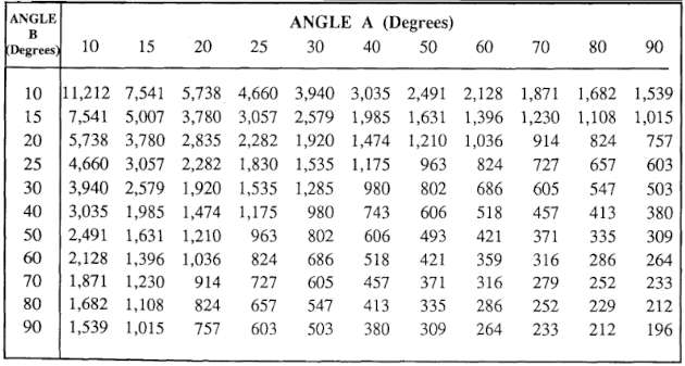
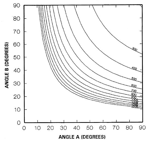
Equation (1) can be used to calculate 2 drms for a three-station loran fix anywhere within the coverage area. Table 1 shows how 2 drms varies with angles A and B. This quantity grows quite large whenever either or both of these angles are small. Figure 2 shows contours of equal value of 2 drms.
In general, as shown in Figure 2, the value of 2 drms is a function of the placement of the master and secondary stations,the user’s location relative to these stations, and the common standard deviation of the TDs.
According to Swanson (1978), the greatest possible accuracy (minimum value of 2 drms) will occur with four stations, each subtending a 90 degree angle with the adjacent station so as to form two orthogonal (at right angles) and uncorrelated LOPS.
The optimal accuracy for this configuration, 2 drms*, is given by the equation:
given the assumed values for each of these parameters.
The geometric dilution of position (GDOP) is defined as the ratio of the actual value of 2 drms corresponding to equation (1) divided by this “best” value, or:
In essence, GDOP measures the ratio of the actual value of 2 drms corresponding to the user’s location in the coverage area of a loran triad to the best possible accuracy of the best possible loran stations. GDOP is a normalized 2 drms, which takes into account the effects of the system geometry and the user’s location.
Table 1 shows the correspondence between GDOP and 2 drms. The specified absolute accuracy of Loran-C is 0,25 NM (1 519 ft), which is equivalent to a GDOP of 10,92.
| Table 2. Correspondence between 2 drms and GDOP | |
|---|---|
| GDOP | 2 drms |
| 1,0 | 139 |
| 1,5 | 209 |
| 2,0 | 278 |
| 2,5 | 348 |
| 3,0 | 417 |
| 3,5 | 487 |
| 4,0 | 556 |
| 4,5 | 626 |
| 5,0 | 695 |
| 6,0 | 834 |
| 7,0 | 973 |
| 8,0 | 1 112 |
| 9,0 | 1 251 |
| 10,0 | 1 390 |
| 12,0 | 1 668 |
| 14,0 | 1 946 |
| 16,0 | 2 224 |
| 18,0 | 2 503 |
| 20,0 | 2 781 |

- Abramowitz, M., et al. “Approximate Method for RapidLoran Computation,” Navigation; Journal of the Institute of Navigation, Vol. 4, No. 1, March 1954, pp. 24-27.
- Alexander, G. “The Premier Racing Tool,” Ocean Navigator, Issue No. 20, Jul/Aug 1988, pp. 37, er seq.
- Anonymous. “Loran: Installation Pitfalls, and How Friendly Should Your Loran Be?” Practical Sailor, Vol. 11, No. 24, December 15, 1985, pp. 1, et seq.
- Anonymous. Manual on Radio Aids to Navigation, International Associationof Lighthouse Authorities, Nouvelle Adresse, 13 Rue Yvon-Villarceau 75 116, Paris, 1979.
- Appleyard, S. F. Marine Electronic Navigation. Routledge and Kegan Paul Ltd., Boston, MA, 02108, 1980.
- Ashwell, G. E., B. G. Pressey, and C. S. Fowler. The Measurement of the Phase Velocity of Ground Wave Propagation at low Frequencies Over a Land Path. Proceedings of the Institute of Electrical Engineering (London) 100 Part III, 1953.
- Bedford Institute of Oceanography. Loran-C Receiver Performance Tests, Bedford Institute of Oceanography, P. O. Box 1006, Dartmouth, NovaScotia, Canada, B2Y 4A2.
- Blizard, M. M. et al. Harbor Monitor System Final Report, CG-D-17-87, ADA 183 477, Dec. 1986, Available through the National Technical Information Service, Springfield, VA, 22161.
- Blizard, M. M., Lt. and CWO 3 D. C. Slagle. Differential Loran-C System Final litter, Draft, United States Coast Guard, January 1987.
- Blizard, M. M. and D. C. Slagle, “Loran-C West Coast Stability Study,” Proceedings of the Fourteenth Wild Goose Technical Symposium, Wild Goose Association, Bedford, MA, 1985.
- Brogdon, B., “Loran Expansion,” Ocean Navigator, Issue No. 42, SeptfOct 1991, pp. 87, et seq.
- Brogdon, W. “Loran Hook, a Little Known, Foible Explained,” Boating, August 1991, p.42.
- Brogdon, W. “Electronic Errors,” Ocean Navigator, Issue No. 40, June 1991,pp. 70, etseq.
- Brogdon, W. “Pathfinders,” American Hunter, Vol. 19, No. 7, July 1991.
- Burt, W. A., et al. Mathematical Considerations Pertaining to the Accuracy of Position, Location, and Navigation Systems, Part I, Stanford Research Institute, 1966. Available from National Technical Information Service, AD-629609, US Department of Commerce, 5825 Port Royal Road, Springfield, VA 2215 1.
- Canadian Coast Guard, Aids and Waterways Branch. A Primer on Loran-C, Ottowa, Ontario, Canada, 1981.
- Connes, K. The Loran, GPS & NAVICOMM Guide, Butterfield Press, 1990.
- Culver, C. “A New High Performance Loran Receiver,” Proceedings of the Sixteenth Annual Technical Symposium, The Wild Goose Association, 20-27 October 1987, pp. 282, et seq.
- Dahl, B. “Adopting Loran-C to Everyday Navigation,” Cruising World,May 1983,pp. 40-45.