In the construction of LNG carriers, ensuring the structural safety and integrity of the vessel is paramount, given the unique challenges posed by the transportation of liquefied natural gas. The design and construction of these ships must adhere to stringent safety standards that consider the cryogenic nature of LNG and the dynamic marine environment. A key element in these standards is the implementation of a SafeHull construction monitoring plan. This plan is designed to enhance the structural robustness of LNG carriers by applying advanced engineering practices and using high-quality materials throughout the construction process. It involves rigorous testing and validation of the vessel’s design through advanced simulation techniques and physical modeling to ensure that the hull can withstand various stress factors, including those from cargo load and sea conditions.
The SafeHull construction monitoring plan also includes continuous oversight and inspection during the building phase to guarantee compliance with safety and quality specifications. Regular checks and balances are conducted to monitor the integrity of the hull, the efficiency of the containment systems, and the reliability of the onboard safety systems. Such meticulous attention helps prevent structural failures and enhances the overall safety of the vessel during its operational life. Additionally, the monitoring plan often extends into the operational phase of the vessel, where periodic inspections and maintenance ensure that the structural integrity remains uncompromised. This ongoing monitoring is vital in adapting to any changes in operational parameters or to address the wear and tear that naturally occurs with time, thus maintaining the vessel’s safety and operational efficiency throughout its service life.
Safehull Construction Monitoring
General
Due to the extremely long design life of LNG’s (up to 40 years) and the very high construction costs, the Safe Hull Construction Monitoring (SHCM) class notation is mandatory. Although this notation and associated design survey requirements are not particular for Liquefied natural gas (LNG) Carrier VesselLNGC’s, it demonstrates the degree of accuracy demanded to satisfy design life and of vessels intended purpose.
In particular, the highest standards (also from the point of view of the inspections) are required in the high stressed areas identified by the Engineering Department as far as:
- fit-up;
- alignment;
- welding;
- NDT and;
- quality control procedures;
are concerned.
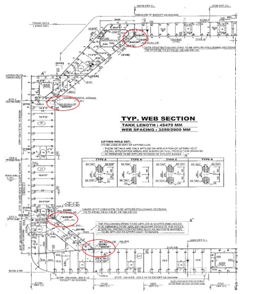
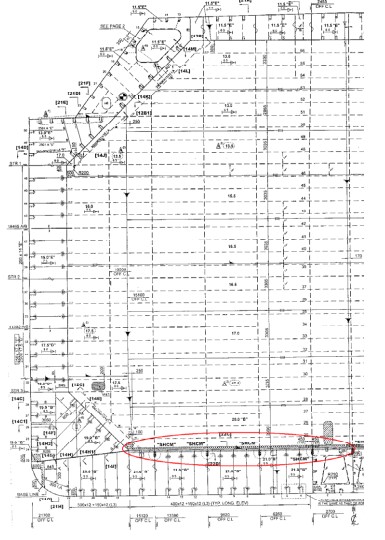
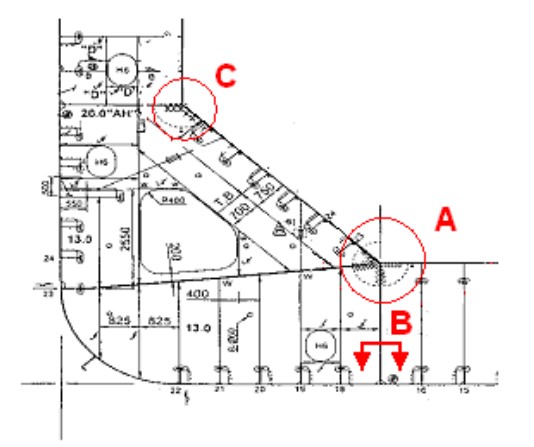
Figures 1 and 2 show a typical approved midship section and transverse bulkhead of a 145 000 m3 LNGC, where the SHCM areas have been indicated by the Engineering Department.
Welding Joint Classification
Critical joints are classified in three categories depending on stage at which they will be inspected:
1) CATEGORY I:
Critical joints at sub-assembly stage.
2) CATEGORY II:
Critical joints at assembly and pre-erection stage.
3) CATEGORY III:
Critical joints at erection stage.
Safehull Construction Monitoring Plan
The content of this sub-chapter is mainly taken from the Attachment B to the ABS Process Instruction SWZ-002-P01-W051 “Safehull Construction Monitoring Program – Survey“. Its content are general and apply to all types of ship, including, of course, LNGC’s:
A OBJECTIVE.
The SafeHull Construction Monitoring Plan is prepared in accordance with The ABS and USCG Additional Rules and GuidesABS Rules, Part 5, Appendix 1, “Guide for SafeHull Construction Monitoring” in association with the class notation of SHCM. The main objective of this plan is to heighten scrutiny of building tolerance and monitoring in way of the identified the critical areas on the approved structural drawings in order to provide an even greater probability of satisfactory in service performance for the subject vessel with SH Notation.
B TOLERANCE LIMIT AND DEFECT CORRECTION METHODS.
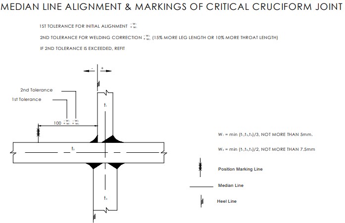
Median line alignment is designed and to be kept as far as possible for the critical areas. The limitation of building tolerance for the critical areas is 1/3 of the thinnest plate in median of cruciform joints. The misalignment should not exceed the limits indicated in the Table 1.
| Table 1. Tolerance Limit and Defect Correction Methods | ||
|---|---|---|
| Details | Tolerance | Repair Standard |
 | a ≤ t1/3 or 5 mm whichever is less measured on the median a1 ≤ (5t1 – 3t2) / 6 or 5 mm whicnever is less measured on hill line Where t3 is less than t1. Then t3 should be substituted for t1 in the standard | t1/3 < a < t1/2 then generally increase weld throat by 10 % A > t1/2 then release and adjust for a length to satisfaction of Surveyor ( a minimum 50 a) |
| a ≤ t1/3 or 5 mm whichever is less measured on the median Where t3 is less than t1. Then t3 should be substituted for t1 in the standard | |
Where misalignment or other defects, greater than the limit is found in any joint of critical areas, the misalignment or defect shall be corrected to the satisfaction of the attending Surveyor. The repair standard indicated in the table is to be followed.
C CRITICAL AREAS.
Typical critical areas of LNGC’s are those indicated in Figures 1 and 2.
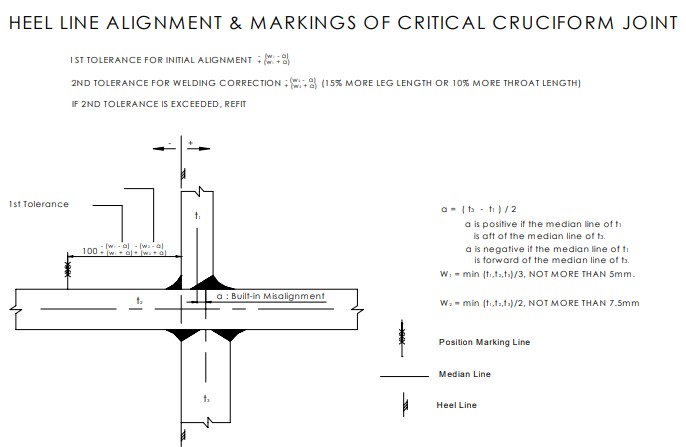
D MEASURING METHOD AND CONTROL PROCEDURES.
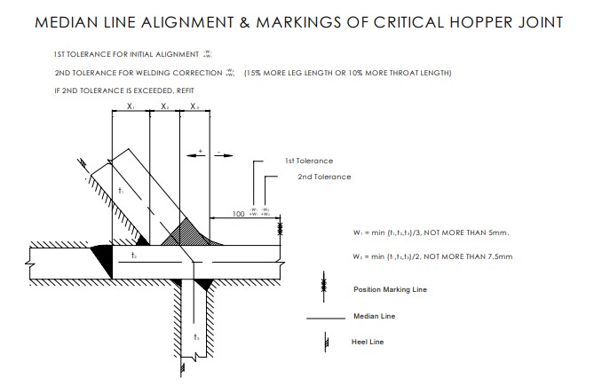
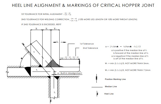
In general, cruciform joints are blind alignment. It is often impractical to directly measure the median lines alignment of structural members; a heel line approach is used in lieu of direct measurement of alignment at median lines. Where the heel line approach is used, the maximum median line tolerances should be converted to heel line values. Reference line, 100 mm off the mold line, is to be marked on both surfaces of continued plates so that the joints can be made with minimal misalignment. Figure 3 shows the fitting design.
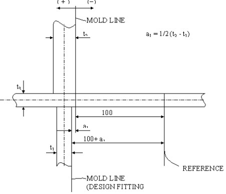
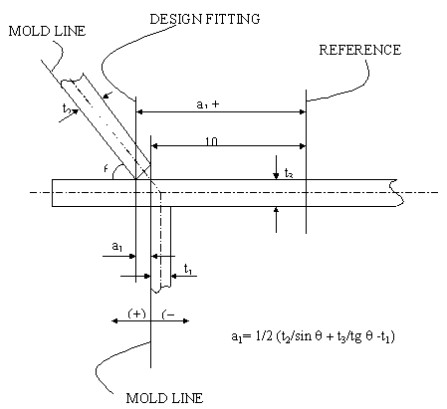
Figure 4 shows the fitting details.
E RECORDING
For all critical joints, the misalignment, if any, is to be verified at each stage of construction and recorded (Figure 5).
Record forms for all the critical joints are to be prepared. Table 2 shows a typical record form for a critical joint.
| Table 2. A typical record form for a critical joint | |||||||
|---|---|---|---|---|---|---|---|
 | |||||||
| Location | Member thickness in mm | a1 in mm | |||||
| t1 | t2 | t3 | Design | Max | Min | Result | |
| Fr. 62 | 16 | 18 | 14 | 1 | 5.7 | -3.7 | |
| Fr. 66 | “ | “ | “ | “ | “ | “ | |
| Fr.70 | “ | “ | “ | “ | “ | “ | |
| Fr. 74 | “ | “ | “ | “ | “ | “ | |
| Fr. 78 | “ | “ | “ | “ | “ | “ | |
| Fr. 90 | 16 | 18 | 14 | 1 | 5.7 | -3.7 | |
| Fr. 94 | “ | “ | “ | “ | “ | “ | |
| Fr. 98 | “ | “ | “ | “ | “ | “ | |
| Fr. 102 | “ | “ | “ | “ | “ | “ | |
| Date | |||||||
| Inspector | |||||||
| Surveyor | |||||||
F NON-DESTRUCTIVE TESTING PLAN.
Plans for non-destructive testing and its record format are to be submitted to attending Surveyor for his review/approval. Upon approval by the Surveyor, the non-destructive testing plans are to be appended to the construction-monitoring plan.
G SURVEY AFTER CONSTRUCTION.
An approved copy of this drawing together with the records of measurement is to be placed onboard in order to monitor critical areas during service as well as provide guidance should future repairs be requested. They are to be available for all subsequent surveys.
H EXAMPLES OF CONSTRUCTION STANDARD FOR ALIGNMENT OF CRITICAL JOINTS.
In general, “ABS Guide for Shipbuilding and Repair Quality Standard for Hull Structures During Construction” can be used for verification of the proposed construction standards. Figures 7 through 10 indicate examples of construction standard for alignment of critical joints for reference.
Standards for alignment for critical areas are at least indicated in the approved Construction Monitoring Plan.