LNG carrier vessel, commonly known as LNGCs, exhibit specific characteristics tailored for the transportation of liquefied natural gas (LNG) across oceans. These LNG carrier vessels are equipped with specialized cargo containment systems, typically consisting of insulated tanks designed to maintain LNG at extremely low temperatures. The design of LNG carriers vessels prioritizes safety and efficiency, with features such as double-hull construction to reduce the risk of leaks in case of collisions or groundings. Additionally, LNGCs often incorporate advanced technology for cargo monitoring, vapor recovery, and emergency response systems to ensure the secure transportation of LNG.
In the event of conventional damage, such as hull breaches or machinery failures, LNG carriers vessels are equipped with stringent safety measures to mitigate risks and prevent potential hazards. Hazardous areas onboard LNGCs, where flammable gases or vapors may be present, are clearly marked and equipped with explosion-proof fittings, ventilation systems, and fire suppression equipment. These precautions minimize the likelihood of ignition and help safeguard personnel and assets. Furthermore, mooring operations for LNG carriers ships are meticulously planned and executed, utilizing advanced techniques and equipment to ensure secure berthing during loading and unloading activities. Dynamic positioning systems and dedicated mooring personnel enhance the vessel’s stability and maneuverability, reducing the risk of incidents in port environments. Overall, LNG carriers vessels are engineered to meet stringent safety standards and regulatory requirements, reflecting the industry’s commitment to safe and sustainable LNG transportation.
LNG Carriers Characteristics
Ship General Arrangment
Today’s LNG carriers are generally single screw, steam turbine driven. They are double hull, longitudinally framed with single deck, transom stern, bulbous bow and no forecastle. All machinery and accommodations are aft. A double bottom extends from the stern to the forward deep tank and a double hull is provided for the full length of the cargo area.
The cargo area is divided with transverse bulkheads or cofferdams to a number of compartments depending on the number of tanks fitted. Transverse cofferdams are fitted at both ends of the cargo area extending full width and depth of the ship.
A duct keel is arranged in the double bottom. It extends from the forward bulkhead of the machinery space to the forward end of the cargo area. Gastight access trunks to the main deck are provided at each end of the duct keel in the cargo area.
The fuel oil tanks are in the machinery space and forward of cargo area.
For the LNG vessels fitted with spherical tanks the blind zone length required by IMO guidelines is satisfied by adjusting the wheelhouse height to the diameter of the cargo tanks. In order not to interrupt the view from the wheelhouse, the arrangement of the outfitting on the tank covers is also considered.
Presently the LNG “standard” carrier vessel based on economics, draft limitations, etc. is ranging from 125 000 m3 to 145 000 m3, in general with 4 tanks, sometimes 5. The four-tank design makes the cargo handing and maintenance easier and reduces the amount of boil-off.
Conventional Damage
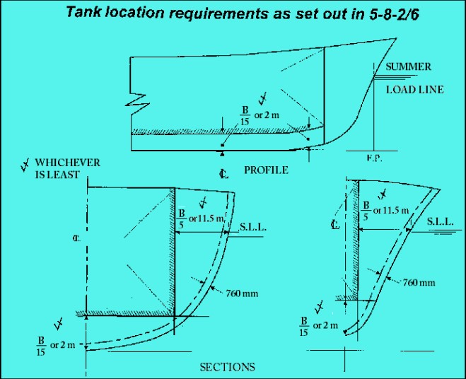
To safeguard the ship and the environment, the cargo tanks are located a specified minimum distance from the side shell in order to be protected in the case of minor damage to the ship resulting from a contact with a jetty, a tug or collision and also a certain distance from the bottom for protection in case of grounding.
Accordingly, the IGC Code established conventional possible damages of the hull to be taken into account in the design of a gas carrier. Table 2 shows the conventional damage extensions established by the IGC Code.
| Table 1. Conventional damage | ||
|---|---|---|
| SIDE DAMAGE | ||
| Longitudinal extent | 1/3 L2/3 or 14,5 m, whichever is less | |
| Transverse extent: measures inboard from the ship’s side at right angles to the centerline at the level of the summer load line | B/5 or 11,5 m, whichever is less | |
| Vertical extent: from the molded line of the bottom shell plating at centerline | Upwards without limits | |
| BOTTOM DAMAGE | ||
| Damage location | For 0,3 L from the forward perpendicular of the ship | Any other part of the ship |
| Longitudinal extent | 1/3 L2/3 or 14,5 m, whichever is less | 1/3 L2/3 or 5 m, whichever is less |
| Transverse extent | B/6 or 10 m, whichever is less | B/6 or 5 m, whichever is less |
| Vertical extent | B/15 or 2 m, whichever is less measured from the molded line of the bottom shell plating at centerline | B/15 or 2 m, whichever is less measured from the molded line of the bottom shell plating at centerline |
The Rules and the The Origins of the IGC CodeIGC Code require that the cargo tanks are located in the holds at a distance from the molded line of the side shell and bottom plating depending on the category of the ship, however this distance can be no where less than 760 mm from the shell plating. Table 1 indicates the minimum acceptable distances of the tanks from the shell depending on the ship category. Figure 1 is a graphic representation of the content of as far as the conventional damage can be extended inside the shell (transverse penetration through side shell and vertical penetration through bottom).
Ship Categories as per IGC CODE
According with the IGC Code the gas carriers may be of one of the following categories depending on the cargo they are intended for, as follows.
Read also: Origin, Applicability, Requirement of IMO Gas Code
Ships subject to the Code should be designed to one of the following standards:
Accordingly, a type 1G ship should survive the most severe standard of damage and its cargo tanks should be located at the maximum prescribed distance inboard from the shell plating.
The ship type required for individual products is indicated in column c in the table of Chapter 19 of the IGC Code.
Definition of Ship Categories
A ship is considered to belong to category 1G, 2G, 2PG or 3G depending on the position of its tanks with respect to the shell and bottom and the location and the extension of the damage along her length. Table 2 details the condition a ship has to comply with to be assigned to a certain category.
| Table 2. Damage standarts for various categories of ship | |||
|---|---|---|---|
| SHIP CATEGORY | DISTANCE OF CARGO TANKS INBOARD | STANDARD OF DAMAGE | |
| TRANSVERSE | VERTICAL | ||
| 1G ship | from the side shell plating not less than the transverse extent of damage specified in Table 1 but not less than 760 mm | from the molded line of the bottom shell plating at centerline not less than the vertical extent of damage specified in Table 1 but not than 760 mm | Damage anywhere in its length (it means at least two compartaments (or more) damaged, if transverse bulkhead are located in way of the conventional length of damage) |
| 2G ship | not less than 760 mm | from the molded line of the bottom shell plating at centerline not less than the vertical extent of damage specified in Table 1 but not less than 760 mm | – As for 1G ships, for ships of more than 150 m in length – Anywhere in its length except involving either of the bulkheads bounding a machinery space located aft, for ships of 150 m in length and less (it means that in the case the bulkhead / cofferdam between the machinery space and the aft hold is in the conventional damage length , both the machinery space and the hold are not to be considered flooded at the same time) |
| 2PG ship | Anywhere in its length except involving transerve bulkheads spaced further apart than the longitudinal extent of damage as specified (it means , that if the transverse bulkheads are locked at a distance greater that the specified damage only one compartment at a time is concidered flooded) | ||
| 3G ship | – As for 2PG ships, for ships of more than 125 m in length – As above and except damage involving the machinery space, when located aft | ||
According with IGC Code requirements LNGC’s are to be considered category 2G. In the table the requirements relative to 2G ships (LNGC) have been highlighted.
Additional Features
All cargo related piping systems are separated from the other piping systems and enter the tanks directly from the open deck. In other words, no Piping System of pressure vessels on gas tankerscargo piping systems are allowed in the double bottoms and cofferdams.
All accommodation spaces are to be located aft of the cargo area. Doors to accommodation spaces and opening windows are not permitted in the bulkhead facing the cargo area, with exception of the wheelhouse windows.
The cargo pump and compressor rooms, as well as the reliquefaction plants, if existing are to be located in the cargo area above the open deck.
Cargo tanks and all dangerous spaces should have hatches and manholes and escape routes such as to make possible to rescue an unconscious person wearing protective equipment.
Mooring
The term mooring refers to the system of securing a vessel to a terminal. The most common terminals for gas carriers are piers. In addition to securing the vessel to the terminal, other shipboard operations fall into the broad category of mooring and require specialized fittings or equipment. Such operations are emergency towing and cargo handling.
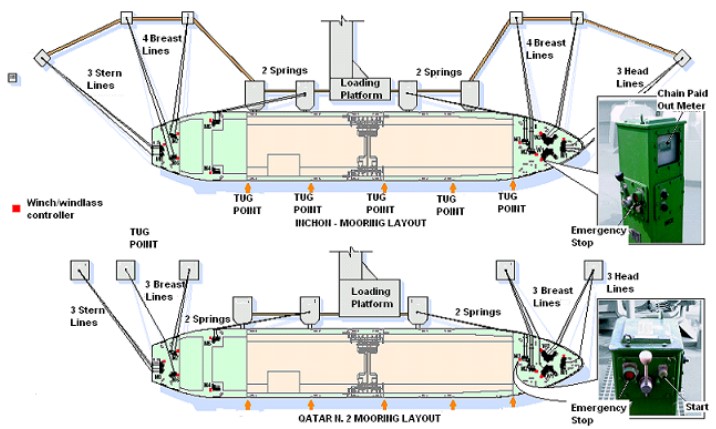
Constant tension winches are used since they allow a reduction of the number of persons needed for the mooring operation, better control of the ship, elimination of line tending during loading/unloading and large rise and fall of tides. In addition, the anchor handling winches have a combined function of windlass/constant tension winch. Hawser sizes are given in the ABS Rules. Usually wire rope lines are provided with constant tension winches. Figure 2 shows the mooring arrangement at Inchon and Qatar terminals.
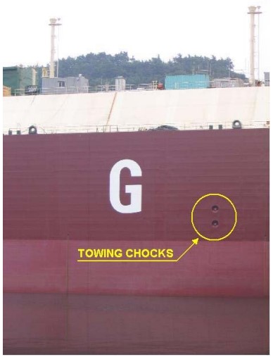
Since large gas vessels typically have a high freeboard, recessed towing chocks are fitted into the side shell at an appropriate height, above the water line for easy handling of the line from the tug. Figure 3 shows a typical recessed towing chock.
The requirements relative to the emergency towing systems of oil carriers apply also to LNGC.
Hazardous Areas
As already mentioned, methane vapor is Flammability, Explosion and other Hazards of Liquefied Gashighly flammable. Accordingly all those areas where LNG vapor is likely to occur in concentration within the flammability range must be considered as hazardous areas. In such areas all the possible source of ignitions are to be strictly avoided. In particular in these areas electrical plant or apparatus are to be absent unless they are strictly necessary. If fitted, both the equipment and the installation are to be suitable for hazardous locations.
The hazardous areas of a gas carrier are defined by the IGC code and Regulations and Rules for Vessels to Carry Liquefied Gasthe Rules as follows:
1 A space in the cargo area, which is not arranged or equipped in an approved manner to ensure that its atmosphere is at all times maintained in a gas-safe condition.
2 An enclosed space outside the cargo area through, which any piping containing liquid or gaseous products passes, or within, which such piping terminates, unless approved arrangements are installed to prevent any escape of product vapor into the atmosphere of that space.
3 A cargo containment system and cargo piping:
- a hold space where cargo is carried in a cargo containment system requiring a secondary barrier;
- a hold space where cargo is carried in a cargo containment system not requiring a secondary barrier.
4 A space separated from a hold space described in 5,0 by a single gastight steel boundary.
5 A cargo pump-room and cargo compressor room.
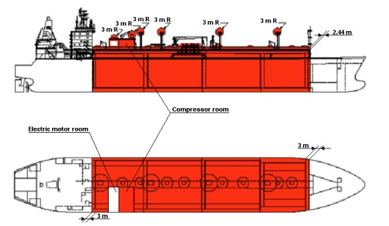
6 A zone on the open deck, or semi-enclosed space on the open deck, within 3 m of any cargo tank outlet, gas or vapor outlet, cargo pipe flange or cargo valve or of entrances and ventilation openings to cargo pump-rooms and cargo compressor rooms.
7 The open deck over the cargo area and 3 m forward and aft of the cargo area on the open deck up to a height of 2,4 m above the weather deck.
8 A zone within 2,4 m of the outer surface of a cargo containment system where such surface is exposed to the weather.
9 An enclosed or semi-enclosed space in, which pipes containing products are located. A space, which contains gas detection equipment complying with 13.6.5 and a space utilizing boil-off gas as fuel and complying with chapter 16 are not considered gas-dangerous spaces in this context.
10 A compartment for cargo hoses.
11 An enclosed or semi-enclosed space having a direct opening into any gas-dangerous space or zone.
The review of the certificates of the electric equipment installed in the hazardous areas and of their installation is of the utmost importance to assure the safety of the ship. This matter will be dealt with more in detail under Module 13.
Figure 4 shows in a schematic way the extension of the hazardous areas in a modern LNGC.