Welding studs play a crucial role in the structural integrity and performance of marine stern gear. These components are subjected to extreme conditions, including high stress, corrosion and constant exposure to seawater. Ensuring that welding studs are properly installed and maintained is essential to prevent failures that could compromise the safety and efficiency of marine vessels.
The reliability of welding studs in marine stern gear depends on the quality of materials used, precise welding techniques and regular inspections. By adhering to industry standards and best practices, marine engineers can significantly extend the lifespan of stern gear, reduce maintenance costs and ensure the vessel’s operational safety in demanding maritime environments.
Stud Welding
General
Studs have two basic functions:
- To act as a visual reference guide during panel positioning.
- To hold the insulation panels to the inner hull during the polymerization of the epoxy mastic (once mastic has fully cured, studs serve no purpose).
Read also: MARK III System: Hull and Deck Components for Marine Vessels
Studs are welded after marking-out and before reference wedges installation. (See Figure 1.)
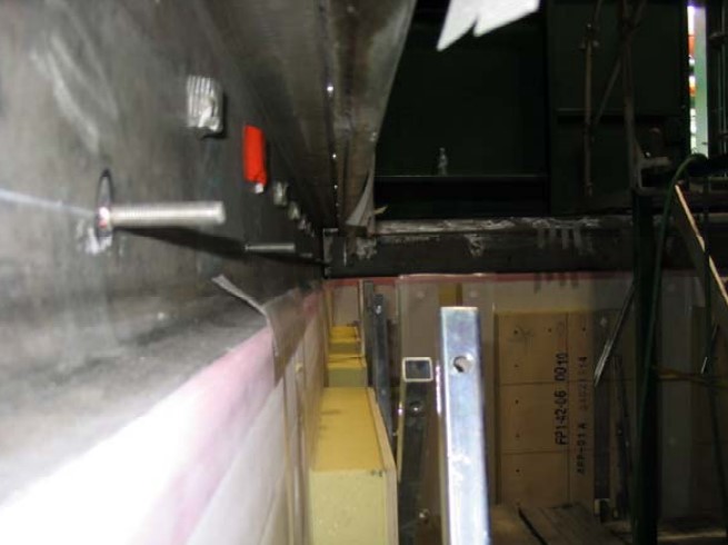
Steel Plating Condition
The cleanliness of the inner hull must be checked in way of the welding areas, moisture, dust and grease need to be removed and if coating is not compatible with the stud weld, the primer paint should be removed by grinding.
Welding
Studs are welded by certified welding operators with a special gun using an approved procedure. Welding Challenges in Aluminum Alloys: Defects and SolutionsA welding procedure is to be carried out. (See Figure 2.)
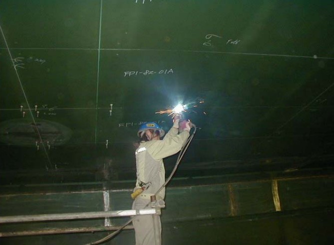
Stud welds are performed individually by centering the stud in the welding gun on the center punch mark.
Studs may also be positioned by mean of template and welded at that time.
Welding Tests
At every shift, morning and afternoon and at each change of welding position, stud welding tests are to be performed by operator in charge following the welding procedure.
- Welding of 4 studs on a test plate in the same position as the bulkhead where the studs will be welded.
- Checking of the appearance quality and dimension.
- Carrying out tensile tests on two studs. Tension load = 800 kg.
- Carrying out 90° bending test on two studs. (See Figure 3.)
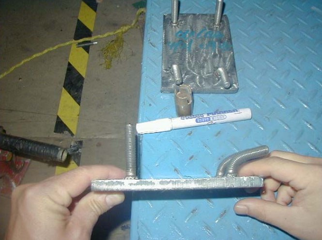
If these tests are satisfactory, the welding work starts. If a failure for any reason, new tests will be performed on new specimen.
Checking of Welded Studs
1) VISUAL EXAMINATION
After welding a visual exam of welded studs will be performed to check. (See Figure 4.)
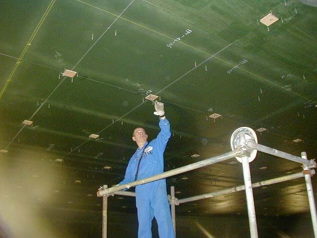
The appearance should be as follows:
- Soundness of the weld: 100 % of studs.
- Undercut less than 0,5 mm; 100 % of studs.
- Studs with defect will be replaced.
2) DIMENSIONAL TOLERANCES
(See Figure 5.)
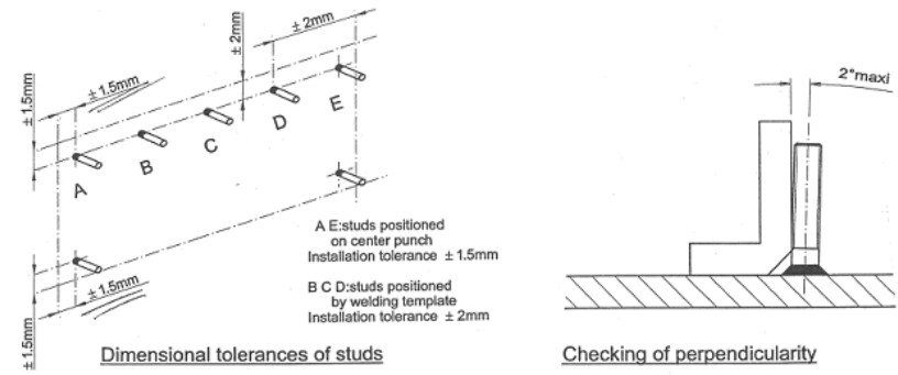
Tolerance should be as follows:
- Positioning of the studs in corner of panels in reference to panel limit line +/- 1,5 mm; 100 % of the studs.
- Positioning of the other studs in reference to panel limit lines: +/- 2 mm.
- 100 % as far as 60 acceptable results, after at random 1 stud line every 30 panels. Misplaced studs will be replaced.
- Inclination < 2°, visual inspection 100 % and cross checking if necessary with right angle gauge. Studs out of perpendicularity can be corrected using soft mallet so as not to damage threads.
3) SOUND TEST
- Sound test with metallic strikes, listening for clear ring tone, 100 %.
- Stud giving back a hollow sound will be replaced.
4) TENSILE TEST
- Studs to be tested at 800 kg.
- For flat panel 10 studs at random every day. No failure is allowed. Studs with defect will be replaced and test carried on with stud welded during this shift until no defect happen on 20 successive studs.
- For corner panels on first 100 studs on time per ship, then at random on 10 % per day of welded studs, no failure is allowed.
Protection of Studs
On bottom and lower chamfers, studs, which can be damaged by trolley, ladders etc. will be protected wit plastic tubes.
Studs for Lath Thickness Fitting
If lath thickness is installed in liquid dome corner, standard stud will be welded on the steel plating, then extension studs will be used for lath thickness and corner pane securing.

