The primary barrier test is a critical component of ensuring the integrity and safety of any system. This framework outlines a structured approach to evaluating the effectiveness of the primary barrier, which is the first line of defense against potential hazards. It includes a series of standardized procedures and criteria for assessing material strength, leakage prevention and overall durability. By following this comprehensive framework, organizations can systematically identify weaknesses and implement necessary improvements to maintain the highest standards of safety and performance.
Complementing the primary barrier test, the secondary barrier test framework provides a detailed methodology for assessing the secondary layer of protection. This framework is designed to evaluate the backup mechanisms that come into play if the primary barrier fails. It encompasses a range of tests to measure the secondary barrier’s resilience, including stress tests, environmental exposure simulations and integrity checks. Adhering to this framework ensures that the secondary barrier is robust and reliable, offering an additional layer of security and reinforcing the overall safety of the system.
Primary Barrier Global Test
Test Principle
This test consists in creating a differential pressure between both sides of the tank walls (double hull and membrane) and in recording the variation of the difference in pressure after a given lapse of time.
This test is essential:
- To check whether the primary barrier walls are perfectly tight when the tanks are loaded.
- To check whether these walls are still tight as compared to the previous test during the scaffolding removal operations till the final fitting operations.
- To confirm that the tank is still tight after the closing of the side opening.
Global test should be commenced in the evening so that a large temperature differential does not distort the results.
This test will include for each tank the following operations:
- creating a vacuum in the insulation spaces (primary and secondary spaces) followed by a recording of the pressure rise in this space. During the operation, the scaffoldings are in place and the inside of the tank is at atmospheric pressure. The resulting vacuum decay curve will be used as reference for the next tests. Tightness check should be continuous during the dismantling of the scaffoldings and fitting operations (pump tower, dome cover etc.);
- successive tests identical to the first test: vacuum pumping in the insulation spaces followed by a recording of the pressure rise, the inside of the tank being at the atmospheric pressure;
- final test after closing the side opening: identical to the first one.
Test Procedure
1) REFERENCE TEST
After checking that the piping connections have been made, that necessary safety devices are in place and pressure inside the tank corresponds to the atmospheric pressure, the global test under vacuum can be carried out as follows.
Raise a vacuum in the insulation spaces (by pumping from the primary space and secondary space) to -800 milllibar +/- 5 % with regard to the atmospheric pressure.
To ensure that the successive tests will be made under the same conditions, the pumping operations will be monitored to follows as closely as possible the vacuum rate curve (4 hours from P. A. to -800 millibar).
Once vacuum has been raised in insulation spaces and stabilized for a period of one hour, all piping will be closed to maintain the difference in pressure created between the insulation space and the inside of the tank for twenty four (24) hours. During this time the following readings will be made:
- Relative pressure in insulation space.
- Relative pressure in the tank if necessary.
- Atmospheric pressure.
- Air temperature in the tank at three different level at least.
- External temperature.
The pressure readings will be taken every ten minutes during the first four hours and every thirty minutes during the following hours.
2) TIGHTNESS TEST DURING THE TANK COMPLETION
Upon satisfactory completion of the reference global test, the scaffolding removal and final tank fitting operations may be carried out as follows.
During all the operations of tank completion, the tightness quality of the tank will be checked continuously by successive tightness tests with measurement of the pressure rise in the insulation space, tests and measurements being repeated daily.
These following tests will be identical to the first test described above.
3) TIGHTNESS CHECK AFTER CLOSING OF THE SIDE OPENING
All the operations for the closing of the side opening being completed, a final test will be carried out under the same conditions as for the first one to confirm the global tightness of the tank.
This test will be identical to the first one described above.
Results Analysis
The reading recorded during the first vacuum test (see Figure below) will serve for drawing up calculation tables, which will be used as reference for the vacuum test carried out during the scaffolding removal and tank closing operations.
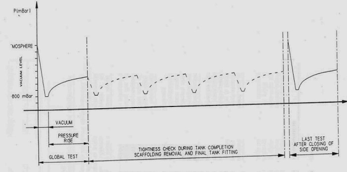
The readings recorded during the tightness test during scaffolding removal and after will be compared with those of the reference test. Any abnormal rise in pressure will be investigated and the causes identified.
Secondary Barrier Tighness Test
This test is performed after completion of the tank construction, before ship delivery and when the ship is in service periodically at intervals as per the The Origins of the IGC CodeIGC Code.
Principle of Test
The test is made by establishing a pressure difference between the primary space and the secondary space and then by recording the variation of the pressure difference in relation to time.
This test supplies the data giving information about the global sealing property of the secondary barrier of each tank. The data obtained during the first test before the delivery will become the reference data for comparison during the ship’s life.
In order to obtain significant comparisons, the test conditions must be standardized and match the condition under, which the reference values were established.
Performance Test
1) PRELIMINARY OPERATIONS
The primary and secondary spaces must be filled with nitrogen or dry air.
All orifices and various openings, which may connect the insulation space to the atmosphere must be made tight.
Safety devices are to be provide for the primary and the secondary spaces.
The pressure must never exceed 25 millibar in the spaces.
During all these operations it is important to make sure that the pressure in the primary space is always higher than the pressure in the secondary space.
2) PRELIMINARY VACUUM TEST OF THE SECONDARY SPACE
The purpose of the preliminary test is to verify that the whole circuit provided for the test is in working order prior performing the actual test.
An initial vacuum is created in the secondary space.
To insure that successive tests will be made under the same conditions, the pumping operations will be monitored to follow as closely as possible the vacuum rate curve (4 hours from atmosphere to -530 millibar).
Once vacuum is established at -530 millibar, pumping is maintained and stabilized at this value for one hour running continuously at a reduced flow rate to maintain a constant pressure.
During this test the primary space will be maintained at the P. A. either by a temporary piping connected to the cargo tank atmosphere or by nitrogen pressurization.
Once the checking is completed and after maintaining the pressure at -530 millibar for one hour, the pumping unit is shut off and all valves closed carefully.
Then the pressure rise inside the secondary space will be observed during 5 hours.
This initial vacuum test will be repeated at least twice.
If during these 5 hours the vacuum decay curve is erratic the initial test will be repeated until a stabilized vacuum decay rate is obtained. The actual test can be initiated.
3) ACTUAL TEST
The test consists of reaching a vacuum pressure of -530 millibar in the secondary space. All operations being identical to the preliminary operation described above.
The pressure in the secondary space will rise due to the entrance of inert gas or dry air from the primary space through Guidelines for Installing and Bonding Secondary Barrier Triplexthe secondary barrier.
During the pressure rise the following parameters will be measured and recorded:
- Pressure in the secondary space.
- Pressure in the primary space.
- Temperature of the atmosphere in the tank and cofferdam.
- External temperature (air and water).
- Time.
- Atmospheric pressure.
Particular care will be taken:
- to make sure of the constant pressure in the primary space equal to the atmospheric pressure (+0, -5 millibar);
- to record accurately the initial time and the evolution of the pressure rise versus time (accuracy for pressure +/-2 millibar).
The pressure rise duration will be limited to 12 hours and eventually less if the pressure of minus 300 millibar is reached in the insulation space prior to this period.
The result of the test has to be summarized by the vacuum decay curve.
Acceptante Criteria
The effectiveness of the secondary barrier is defined by the “Normalized porosity Area” (NPA).
The NPA is a function of the required time for a pressure rise between -450 millibar and -300 millibar, the secondary barrier area and the secondary space volume.
1) CALCULATION OF THE NPA
The vacuum decay test can be performed with either dry air or nitrogen during the test.
Following the case, NPA determination will be:
- Case A: nitrogen at 21 °C as test gas:
- Case B: air at 21 °C as test gas:
.
Where:
- NPA: normalized porosity area in m2;
- Asb: secondary barrier area of considered tank in m2;
- Δt: time for the pressure rise between -450 and -300 millibar in hours;
- Vis: free volume of secondary space in m3
.
2) CONSTRUCTION CRITERIA
The value of the NPA for a LNG carrier built according to MARK III System: Hull and Deck Components for Marine VesselsMARK III system with a secondary insulation thickness of 170 mm (total thickness being 250 or 270 mm) is
It should be noted that this value is linked with the above secondary insulation thickness.
3) IN SERVICE CRITERIA
It has been shown that the secondary barrier porosity increases as a function of the ship service, this evolution being mainly due to the effect of full thermal cycles (micro porosity created in the glue lines) applied to the containment system in case of dry docking operation for instance.
The calculated in service NPA is a function of the Cumulative Thermal Cycles (CTC).

- The Society of International Gas Tanker and Terminal Operators (SIGTTO). Liquefied Gas Handling Principles on Ships and in Terminals (LGHP4) / 4th Edition: 2021.
- The international group of liquefied natural gas importers (GIIGNL). LNG custody transfer handbook / 6th Edition: 2020-2021.
- American Gas Association, Gas Supply Review, 5 (February 1977).
- ©Witherby Publishing Group Ltd. LNG Shipping Knowledge / 3rd Edition: 2008-2020.
- CBS Publishers & Distributors Pvt Ltd. Design of LPG and LNG Jetties with Navigation and Risk Analysis / 4th Edition.
- NATURAL GAS PROCESSING & ITS ENERGY TRANSITION ROLE: LNG, CNG, LPG & NGL Paperback – Large Print, November 14, 2023.
- American Gas Association, Gas Supply Review, 5 (February 1977).
- The Society of International Gas Tanker and Terminal Operators (SIGTTO). Ship/Shore Interface / 1st Edition, 2018.
- Department of Transportation, US Coast Guard, Liquefied Natural Gas, Views and Practices Policy and Safety, p. IV-3.
- Department of Transportation, US Coast Guard, Liquefied Natural Gas, Views and Practices Policy and Safety, p. IV-4.
- Federal Power commission, Trunkline LNG Company et al., Opinion No. 796-A, Docket No s. CP74-138-140 (Washington, D. C.: Federal Power Commission, June 30, 1977).
- Federal Power Commission, Final Environmental Impact Statement Calcasieu LNG Project Trunkline LNG Company Docket No. CP74-138 et al., (Washington, D. C.: Federal Power Commission, September 1976).
- Federal Power Commission, «FPC Judge Approves Importation of Indonesia LNG».
- OCIMF, ICS, SIGTTO & CDI. Ship to Ship Transfer Guide for Petroleum, Chemicals and Liquefied Gases / 1st Edition, 2013.
- Federal Power Commission, «Table of LNG imports and exports for 1976», News Release, June 3, 1977, and Federal Energy Administration, Monthly Energy Review, March 1977.
- Office of Technology Assessment LNG panel meeting, Washington, D. C., June 23, 1977.
- Socio-Economic Systems, Inc., Environmental Impact Report for the Proposed Oxnard LNG Facilities, Safety, Appendix B (Los Angeles, Ca.: Socio-Economic Systems, 1976).
- «LNG Scorecard», Pipeline and Gas Journal 203 (June 1976): 20.
- Dean Hale, «Cold Winter Spurs LNG Activity»: 30.