Risk assessment and process safety management are crucial components of ensuring operational integrity and safety within any organization. These practices are designed to identify potential hazards, evaluate risks, and implement measures to mitigate or manage those risks effectively. This comprehensive guide aims to provide an in-depth understanding of the principles, methodologies, and practical applications involved in risk assessment and process safety management.
- Process Safety
- Risk Assessment
- Principles of risk assessment
- Qualitative versus quantitative
- Inherent risk versus residual risk
- Risk assessments in practice
- Procedures
- Standards
- Management of Change (MoC)
- Inspection and Maintenance
- Permit to Work Systems (PTW)
- Types of permit to work
- Lock-out and tag-out
- Incident Investigation and Reporting
- Incident reporting
- Root cause analysis (RCA) and risk assessments
- Process Safety Information
Risk assessment is the systematic process of identifying, analyzing, and evaluating risks associated with various operations or activities. It involves differentiating between qualitative and quantitative approaches, understanding the nuances of inherent versus residual risks, and applying these concepts in real-world scenarios. This guide will delve into the key principles of risk assessment, offering insights into best practices and procedures that ensure thorough and accurate evaluations.
Process Safety
“Process safety is a blend of engineering and management skills focused on preventing catastrophic accidents and near misses, particularly structural collapse, explosions, fires and toxic releases associated with loss of containment of energy or dangerous substances such as chemicals and petroleum products” (As defined by the Center for Chemical Process Safety of the American Institute of Chemical Engineers).
In the case of the carriage of liquefied gas at sea, the goal of process safety is to prevent an unplanned or uncontrolled sequence of events resulting in a loss of containment and one or more of the following consequences:
- fatalities;
- asset destruction;
- environmental damage;
- public endangerment.
Process safety needs to be considered separately from personal safety. Process safety begins at the very start of a project and continues through design, operation, and decommissioning of the equipment.
The approach applies to new equipment and systems added to the project during its life, as well as the equipment and systems modified during the project’s lifecycle.
Risk Assessment
The ISM Code states that one of the safety management objectives of a Company should be to “assess all identified risks to its ships, personnel and the environment and establish appropriate safeguards”. The ISM Code does not specify any particular approach to risk management, but whatever approach is used will usually be designed to be systematic to ensure that the assessment and associated results are complete and effective.
Effective process safety management requires a thorough understanding of the risks involved so that the means to prevent and control them can be put into place and maintained.
The IMO, in its “Guidelines for Formal Safety Assessment (MSC/Circ. 1023, MEPC/Circ. 392)” defines risk as:
“The combination of the frequency and the severity of the consequence”.
Principles of risk assessment
Risk assessments are used to ensure that hazards are identified and mitigated sufficiently. A risk assessment is a systematic process of evaluating the potential risks that may be involved in a projected activity or undertaking. The risk assessment process looks at:
- identification of hazards;
- evaluation of risks associated with the identified hazards;
- application of controls to reduce the risks that are deemed unacceptable;
- monitoring the effectiveness of the controls.
This process may be illustrated by a modelling technique such as the “Swiss Cheese” analogy, which can show how unidentified failures may align to result in a more significant incident (see Figure 1).
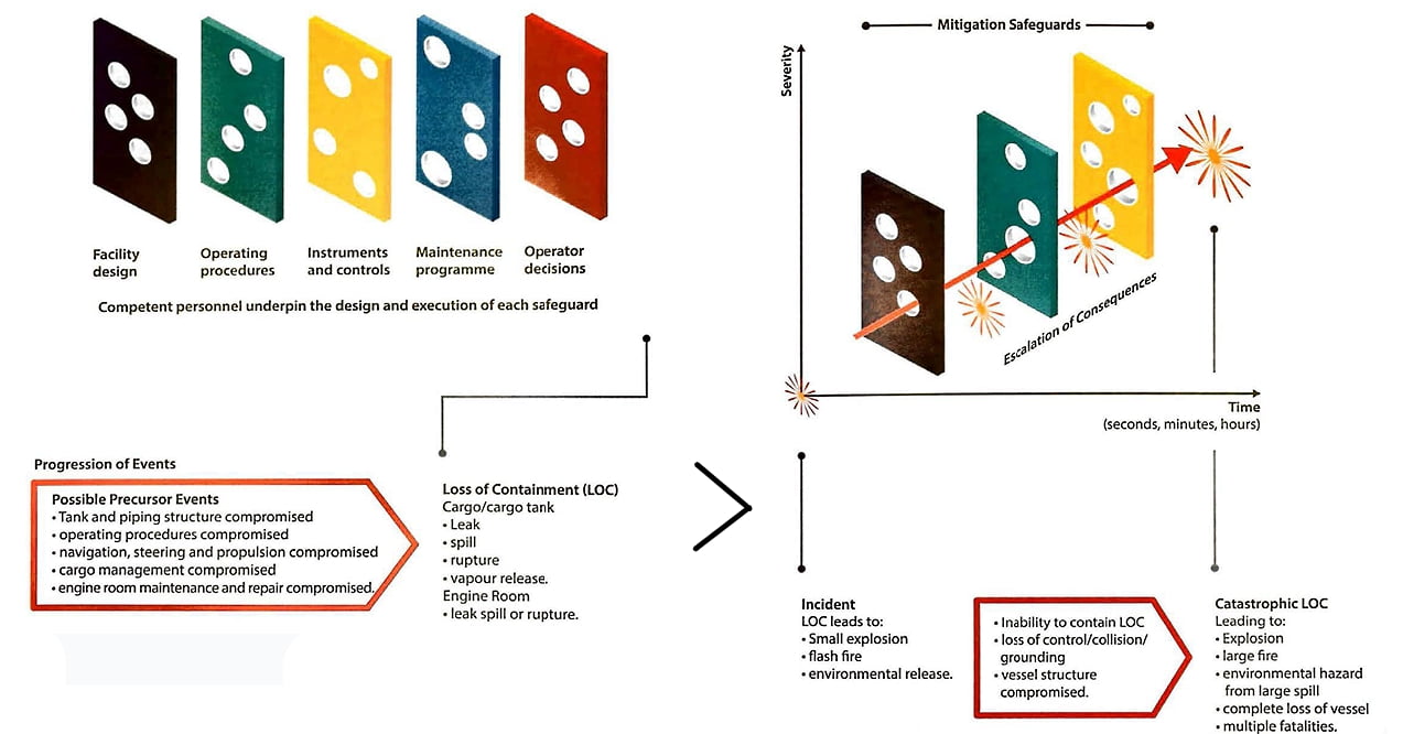
Structured techniques are used to identify accident scenarios and how they can be prevented or controlled. Numerous techniques are available for hazard and risk assessment including, but not limited to:
- hazard identification (HAZID) and operability studies (HAZOP);
- what-if? (or checklist analysis);
- failure mode and effects analysis (FMEA);
- fault tree analysis (FTA) and event tree analysis (ETA).
Whichever technique is chosen, the outcome should be a list of scenarios requiring consequence analysis, yielding recommendations for steps to be taken for the specification, detailed design, operating procedures, training and implementation of appropriate safety measures.
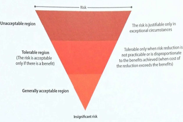
The magnitude of the consequences will govern the acceptability of the risk and, therefore, the extent of effort and cost applied to controlling the risk. The principle of ALARP is applied to such risks and describes the level to which workplace risks might practicably be controlled. There is no simple formula for computing what is ALARP. The effort is not one of balancing the costs and benefits of control measures, but of adopting measures that are appropriate.
Qualitative versus quantitative
A qualitative risk assessment is a subjective risk assessment that allows quick identification of potential risks and the assets and resources that are vulnerable to them. A standard qualitative assessment would be a HAZOP and its aims in risk analysis are to gain a level of risk reduction that is acceptable and to increase the awareness of the hazard.
A quantitative risk assessment looks at low probability events with serious consequences and starts by taking an inventory of potential hazards, their likelihoods and consequences. The likelihoods are usually based on available statistical information and the quantified risks are then assessed by comparison against defined criteria.
Inherent risk versus residual risk
Inherent risk is the level of risk if there are no barriers or controls in place, which represents the worst case scenario, often associated with the management level, as it is generally considered to be a part of the design and planning of a system or process.
Residual risk is the level of risk with all of the barriers or controls in place. It is associated with operational level as it is the risk generally considered by the operators of a process or system.
Risk assessments in practice
While there are many guidelines available on how to undertake a risk assessment, there are several factors to consider, including but not limited to:
- the type of ship;
- the nature of the operation being considered;
- the specific type and extent of hazards and risks.
The process will usually be simple, requiring identification of the hazards that are present in a planned activity and then identification of the significant risks associated with it. Consideration of existing precautions to control the risk, such as procedures, permits to work or PPE, will also usually
be included.
The risk assessment process will normally be seen as a continuous one. Assuming no valid assessment exists for a particular activity, the risks will be assessed before any work or operation begins. The process will normally include a review, allowing for the assessment to be updated as necessary to help to ensure that it reflects current design, operations and procedures.
Procedures
Operational procedures and instructions will usually be developed to cover normal, abnormal, and emergency conditions. For ships, in addition to the ISM Code, the IGC Code in any event requires such procedures to be provided onboard for each product carried.
It is important to recognise that risk assessments are based on following proper procedures. With this in mind, procedures can be expected to be written with sufficient detail and related to the criticality of the systems/equipment, and to address both operation and maintenance of such systems/equipment.
It may be prudent for procedures to be developed by parties who are knowledgeable of both the design basis and the operational requirements of the system/equipment. A complete procedure will, in addition to describing applicable safe work practices, consider human factors and include clear roles and responsibilities.
Standards
Various rules, regulations, and standards will be applied to the design and operation of a facility, including international standards such as the International Organization for Standardization (ISO), the International Electrotechnical Commission (IEC) and region-specific standards. Governments and coastal States have jurisdiction over shore-based and offshore facilities and may require certain standards to be applied to a facility. For ships, the regulatory framework is described in article “Overview of the Carriage of Liquefied Gases by SeaRegulatory Framework“.
In addition to standards, rules and regulations, there are also industry guidelines, such as those published by SIGTTO and other industry bodies.
It is important to note that conformance with standards may not result in ease of use or operation. Flag Administrations and Classification Societies are continually introducing improvements for safer designs through regulations, often known as “minimum requirements or standards“. However, the term “standard” is subjective and can mean different things to different groups outside of the regulated regime.
Management of Change (MoC)
MoC procedures are intended to ensure that changes to ships and terminals are properly reviewed and approved prior to implementation, by persons with the requisite expertise in an effort to eliminate workplace hazards that could lead to injuries, equipment damage or environmental impact. MoC will usually address both permanent and temporary change. Temporary change reviews and approvals will typically specify the duration of the change and will require review if an extension is required.
At the operational level the following areas, amongst others, will usually be covered by MoC procedures:
- product changes;
- procedure changes;
- personnel changes;
- engineering changes;
- IT changes;
- emergency changes.
Product changes
Changes to the specification of an existing product will usually require new handling and storage procedures.
The MoC procedure ensures that, for example:
- all liquefied gases and chemicals are correctly handled;
- the senior officers are aware of any health, safety and compliance issues;
- the liquefied gas or chemical can be safely handled.
Procedure changes
Requests to change an operating procedure may be raised by any member of the ship’s crew and will usually be dealt with by the Safety Officer. However, any significant or complex change will usually fall into the MoC system so that the impact on other areas of the vessel or its operation can be considered.
Personnel changes
The MoC procedure for personnel is likely to be initiated when:
- an existing crew member or operator is promoted into a new position that is safety critical;
- a new position is established that is safety critical.
Engineering changes
The MoC procedure for engineering changes will typically be initiated after a full review by the engineering and operational personnel has ascertained that there are some wider issues that need consideration. This would include changes that:
- affect safety and environmental activities;
- affect fire protection;
- affect handling and storage conditions;
- increase chemical hazards;
- demand additional training requirements.
Engineering changes will usually not proceed until all the items have been considered and signed off through the MoC process.
IT changes
It is usually preferable that changes to technology are carefully planned to minimise any potential systems conflicts or failures to current operating systems.
Proposed technology changes will usually fall into the MoC procedures, with the possible exception of small, localised hardware changes or to non-critical standalone software.
Emergency changes
While there will sometimes be a need to make unplanned or emergency changes, these will usually be risk assessed. Any impact on personnel working conditions arising from the changes will usually need to be fully evaluated. A full MoC procedure will usually be carried out as soon as is practical after any emergency change.
Inspection and Maintenance
Regular inspection and maintenance is a vital part of ensuring the continued safety on board a ship. From fire and safety equipment to hull coatings, there are a wide variety of items that may be included in programmes of inspection and maintenance.
The maintenance programme specified by the ship’s Class Society is known as the planned maintenance system (PMS) and must be followed in order for the ship to comply with Class requirements. It is a mandatory requirement under Section 10 of the International Safety Management (ISM) Code to have a PMS on board. The IMO also provides other guidelines for maintenance and inspection of specific items, such as SOLAS Regulation II-1/3-9 concerning the “means of embarkation on and disembarkation from ships” which covers the inspection and maintenance of gangways and accommodation ladders.
International Safety Management (ISM) Code
“10 Maintenance of the ship and equipment.
10.1 The company should establish procedures to ensure that the ship is maintained in conformity with the provisions of the relevant rules and regulations and with any additional requirements which may be established by the company.
10.2 In meeting these requirements, the company should ensure that:
- inspections are held at appropriate intervals;
- any non-conformity is reported, with its possible cause, if known;
- appropriate corrective action is taken;
- and records of these activities are maintained.
10.3 The company should identify equipment and technical systems the sudden operational failure of which may result in hazardous situations. The safety management system should provide for specific measures aimed at promoting the reliability of such equipment or systems. These measures should include the regular testing of stand-by arrangements and equipment or technical systems that are not in continuous use.
10.4 The inspections mentioned in 10.2 as well as the measures referenced to in 10.3 should be integrated into the ship’s operational maintenance routine.”
The International Association of Classification Societies (IACS) is on organisation that prepares rules and guidelines to be used by its 12 member organisations. These ensure standardisation of safety processes and structural properties across the industry and include several publications related to maintenance, inspection and survey of different elements of a ship:
- maintenance and inspection of electrical equipment on the ship;
- periodic survey and testing of foam concentrates and CO2 halon containers;
- guidelines for surveys, assessment and repairs of hull structures.
The ship’s Classification Society will usually include other planned maintenance and testing as part of the vessel safety surveys. Regular inspection and testing of life rafts, fire safety equipment and global maritime distress and safety systems (GMDSS) are all covered in the safety surveys and certificates will need to be on board to prove compliance with the necessary safety regulations.
P&I Clubs may also require inspections to ensure that ships are meeting the necessary standards and remain safe working environments for the crew and workers in port. These inspections usually cover safety-related items, equipment and processes related to pollution control, cargoworthiness and structural tests. P&I Club inspections can cover procedures and documentation as well as examination of physical items on board.
In addition, owners and operators may have their own procedures for other inspections and maintenance. Efficient record-keeping and documentation are required to ensure that requirements from all parties are met.
It is important to maintain checklists of planned maintenance and inspections to record when tasks are completed and any deficiencies or non-compliant items noted. Records will, typically, also include details of any work undertaken to repair items that do not meet specifications and any follow-up inspections that are required.
Permit to Work Systems (PTW)
Permit to work (PTW) systems provide a structured and auditable approach to safe working by:
- safeguarding those who are performing the work;
- safeguarding others who may be affected by the work;
- safeguarding the work location;
- ensuring compliance with legislation and regulatory requirements.
The approach used to identify the need for permits and specialised procedures will usually include:
- appointment of a knowledgeable and experienced team;
- a clear description of the nature of hazardous work;
- assessment of the work to identify the need for and types of permits and procedures to control hazardous activities, which may or may not be gas-specific, such as:
- cold work;
- hot work;
- confined space entry;
- work on electrical equipment and systems (eg electrical isolation certificates and lock-out/tag-out procedures);
- working in the vicinity of tanks, pipeline and/or equipment under inert gas;
- working on safety critical equipment, including temporarily bypassing alarms to allow for such work;
- working on cargo tanks, pipelines, pumps and/or machinery;
- working at height;
- working over water;
- asbestos working;
- vehicle entry;
- equipment removal;
- scaffolding;
- working under water;
- working on high pressure equipment.
A list of permits required will usually be compiled, together with a detailed description of the nature of the work to be covered by the permits. The operations listed above will usually only be carried out after a specific written permit has been issued.
To ensure continuous improvement, a regular audit and review of the effectiveness of the permit system will usually be carried out.
General rules for all PTW systems
Usually there will be a clear and unambiguous definition of the types of work that require a permit and the types of work that do not require a permit, as well as delineation of hazardous zones where the permit system applies, together with safe areas where some activities may not require permits.
The permit should specify clearly:
- the scope of the permitted work;
- the particular item of equipment or area involved;
- steps needed to prepare the equipment or area for the intended work;
- other equipment required to do the job properly;
- the foreseeable hazards and the precautions to be adopted to execute the work safely;
- the PPE to be used;
- the permit’s period of validity (in general, no permit will have a validity longer than 24 hours);
- reference to other specific permits that may be in force during the period and affecting the same area/system.
Typically, the permit will include a checklist of all the conditions to be met before it can be used.
A signed copy of the permit will usually be displayed at the work site and a copy retained for future audits/inspections.
Clear designation is also required of, for example:
- The personnel responsible for issuing and authorising the permits (they will usually not be the same person) to indicate that, for example:
- all necessary procedures and plans have been prepared and are in place including isolation procedures, checklists, blanking schedules, etc.;
- the appropriate risk assessment of the activity and its location has been completed;
- measures to control the potential hazards are in place, eg isolations, gas-freeing, etc.;
- PPE and safety equipment have been specified;
- the personnel responsible for carrying out and monitoring specific gas testing requirements;
- the personnel responsible for isolating and re-energising electrical service supplies;
- the personnel responsible for applying locks/isolations under the lock-out/tag-out procedure for the isolation of valves, pumps, motors, switches, starter switches or any other control item that could lead to inadvertent or unscheduled activation of any equipment;
- the safety personnel who have provided specific guidance on the permits;
- the personnel responsible for accepting the permit following completion of the hazardous activities.
The permits will typically include sections for equipment name, identification number and description and clearly define the specific scope of the work to be carried out and the location.
Communication
All personnel involved in controlling the working environment and in performing the work should fully understand:
- the potential hazards of the work;
- the control measures in place;
- the cooperation required between performing and authorising personnel;
- the actions to be taken in on emergency;
- cross references to other permits.
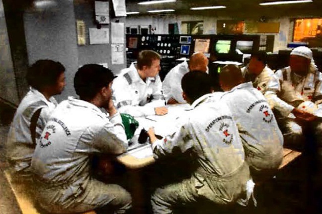
This con be achieved through a “toolbox talk“, which is a briefing of everyone involved in carrying out the work. The briefing makes workers aware of the plans for the job, the procedures to be followed, potential risks, precautions and individual responsibilities.
Equipment to be used for maintenance should be suitably identified as such, eg with hazard and safety warning notices, a delineated area and togging of equipment (ie cross referenced where possible to an isolation/blanking schedule). Copies of permits, such as for cold work, hot work, electrical isolation etc., should be displayed on the equipment at the work site.
The permit will usually also specify the actions to be taken in the event of specified equipment being unavailable, weather conditions changing, the type of work changing etc.
As a general principle, all work under the control of a work permit will usually cease immediately and the permit cancelled and withdrawn if an emergency alarm sounds. The permits will then be returned to the issuing authority and work will not recommence until the issuing authority is satisfied that all conditions comply with permit requirements.
Completion of work/acceptance of work
It is common for a job in progress to be periodically inspected by a competent person. On completion of any hazardous work involving a work permit, the completed work will usually be examined by both the issuing and performing authorities to ensure it has been carried out satisfactorily and the permit endorsed accordingly.
Types of permit to work
This section illustrates typical examples of permits to work.
Cold work permit
This type of permit is used where the work is in a hazardous or dangerous area that will not involve the generation of temperatures likely to be of sufficient intensity to cause ignition of combustible gases, vapours or liquids in or adjacent to the area involved.
Hot work permit
A hot work permit is used where the work involves flames or temperatures high enough to ignite flammable or combustible material, eg:
- burning,
- welding,
- soldering,
- grinding etc.
Before hot work is started on any equipment or container, even if such equipment has been isolated, flushed or otherwise cleaned, tests for possible flammable vapour concentrations will be conducted by a trained person using a combustible gas indicator.
Periodic tests should be conducted to ensure that the work area remains safe during hot work.
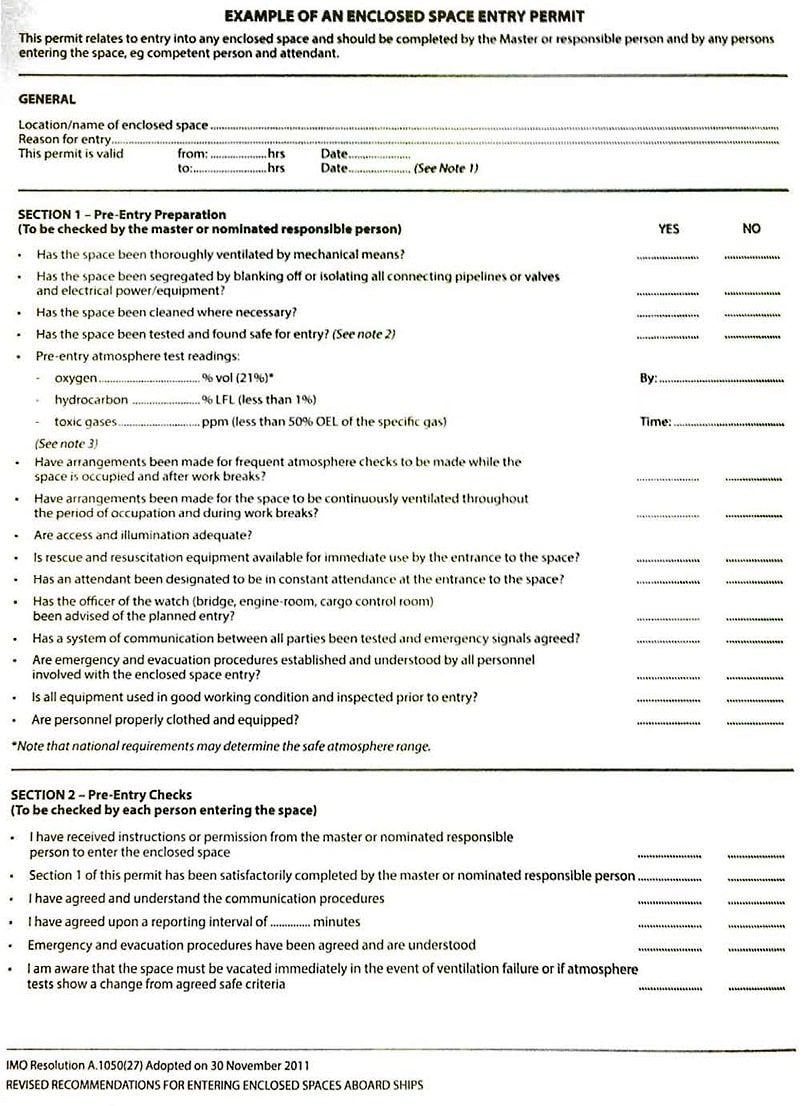
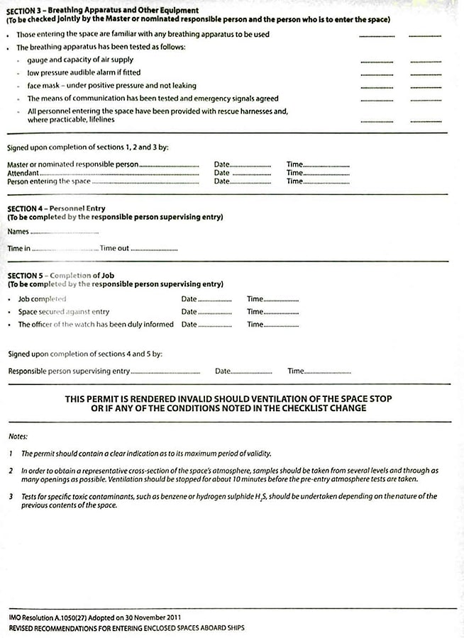
Enclosed space (confined space) entry permit
An enclosed space is a potentially dangerous work area as it may have restricted access, lack of continuous ventilation and, possibly, a hazardous atmosphere due to the presence of flammable, corrosive, toxic or inert gas or due to oxygen deficiency.
Therefore, effective control measures should be in place to enable those working inside a confined space to carry out their work safely. This will typically include the issuance of an enclosed space entry permit.
The permit will show whether entry into the enclosed space can be made with or without breathing apparatus. If breathing apparatus is not required, the permit should indicate how an adequate supply of breathable air is to be maintained.
Before issuing the permit, the issuer will, for example, usually be expected to:
- ensure that the area to be entered is withdrawn from service and isolated by positive disconnection or blanks;
- set down the requirements for cleaning and purging and check that they are properly satisfied;
- ensure that relevant tests are conducted of the atmosphere inside the enclosed space;
- ensure that an adequate supply of breathable air is available to testers and workers charged with entering the confined space;
- check that specific precautions have been taken.
Atmosphere testing
Any decision to enter an enclosed space should only be taken following comprehensive testing of the atmosphere in the enclosed space. Testing should be carried out by competent persons using equipment that is of the approved type, properly maintained, calibrated against standard samples and fit for purpose.
Tests should be carried out For flammable and toxic atmospheres and for oxygen deficiency.
If entry is to be made into a large confined space, a number of representative tests should be taken across a cross-section of the enclosed space.
Results of all tests carried out should be retained.
Personal detectors and continuously monitoring analysers, fitted with crucial and usual alarms, should be used where possible to provide ongoing monitoring of the atmosphere in the enclosed space.
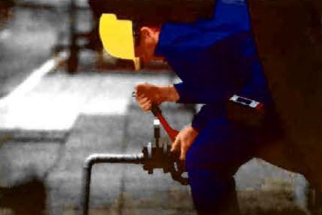
Lock-out and tag-out
The aim of a lock-out/tag-out system is to ensure that, when any work is to be carried out on a pipeline or electrical system, the system is placed in a safe condition by isolating the area to be worked on from the rest of the system so that no unexpected release of energy or pipeline contents can occur.
Isolation of energy systems, whether mechanical, electrical, process, hydraulic or other, should not proceed unless and until:
- the methods of cut-off and discharge of stored energy have been agreed and carried out by trained and competent persons;
- any stored energy or trapped pressure is released;
- an effective system of locks and tags is used at all isolation points;
- tests are carried out to ensure that all isolations are effective;
- the isolations are monitored at periodic intervals.
Once the power sources are identified, normally through the use of power distribution diagrams, the power sources are typically isolated by:
- switching off power from the electrical source by using the isolator;
- checking at the relevant panel that the system is not live by using approved dead line indicator tests to confirm that fuses are electrically isolated;
- removing fuses;
- locking and tagging the isolator;
- recording the lock-out/tag-out in the respective register or log book.
Secondary power sources to the equipment to be worked on, for example back-feed from the emergency switchboard, will need to be identified and isolated as well.
The effectiveness of the isolation will usually be confirmed by trying to operate the component or equipment remotely and also by trying any local stop/start buttons.
For fluid (liquid) systems, isolation will typically be achieved by applying physical isolation, usually in the form of:
- physical disconnections;
- double or single block and bleed with spades or blank flanges.
After isolation of the equipment and before any work commences, any residual product should be drained to a safe area and any trapped pressure vented. The effectiveness of the isolation will typically be confirmed by carefully opening test cocks or drain valves on the pipelines.
Discharge of any stored energy in electrical systems will be specific to the equipment, but will typically consist of actions to discharge stored power in capacitors, batteries and inductive loads.
Physical lock-out/tag-out systems have a system of locks and tags that are installed at the nominated isolation points by trained and competent personnel. Keys and padlocks will be held by the person performing the work or retained for safe custody in, for example, a lock-out/tag-out cabinet in the control room. Where more than one area can be affected by removal of any locks or tags, multiple padlocks may be used, one for each affected work site or system.
Tags will usually indicate:
- the name of the equipment being isolated;
- pipeline or circuit references;
- date of isolation;
- name of the person applying the isolation;
- job/maintenance request number or work permit number.
It is prudent for all crew members to receive training on the lock-out/tag-out procedure and records kept accordingly.
Personnel authorised to perform lock-out/tag-out will usually need to know how to identify energy sources, perform the procedure, remove lock-out devices and follow the methods used to isolate energy sources on equipment. Other personnel will typically be trained on, for example, the importance of the procedure, how to recognise lock-out/tag-out devices and the implications relevant to their work.
Incident Investigation and Reporting
Incident reporting
Incident reporting forms a fundamental part of providing feedback to the effectiveness of SMS and MoC systems, enabling regulatory reporting and providing input to the PTW and risk assessment procedures.
An important part of the system is the classification of any incident, accident or non-conformances and the definitions of these will be determined by corporate policy, regulatory environment and degree of potential hazard.
The mechanical aspects of incident reporting and feedback will be specific to the terminal or liquefied gas carrier and will be part of the operating procedures.
| Incidents, accidents and non-conformances | |
|---|---|
| Incident | Any unexpected, unplanned and undesirable event. |
| Minor Incident | An incident that results in only minor injury or equipment damage. Corrective action is likely to be obvious and quickly implemented. |
| Major Incident | An occurrence that results in (or hos the potential to result in) a loss of time or damage to health, environment or property, or resulted in (or had the potential to result in) a catastrophic release of highly hazardous chemicals or liquefied gases. |
| Non-conformance | An observed situation where objective evidence indicates the non-fulfilment of a specified requirement of the ship or facility’s SMS. A non-conformance may include defects or malfunctions. |
Near miss
A near miss is an undesired event (ie unsafe act or unsafe condition) that, under slightly different circumstances, may have resulted in physical harm to personnel, equipment damage, hazardous material release or product loss. They are categorised as major or minor, based on the potential level of hazard.
If a near miss is categorised as major, it will usually be investigated in the same way as an incident.
Reporting
All personnel should report any incidents, non-conformances or near misses to the nominated Safety Officer, and any other applicable individuals, as soon as possible after occurrence or discovery.
There will also normally be o requirement to report to Head Office, via the DPA, within a specified timescale, depending on the nature of the incident. There will also be regulatory requirements for reporting and these must form a clear part of any incident reporting system.
Investigation and analysis
It is prudent for an incident checklist to be readily available to ensure all relevant information is provided and notifications made during incident reporting.
If on incident occurs, immediate care will be given to any injured parties, but the physical scene of the incident will usually be left undisturbed unless approval is obtained from the investigation team leader or unless a serious personnel, environmental or property hazard exists. If the scene is to be disturbed it may be prudent, where circumstances allow, to take pictures to document the original conditions.
The information needed to conduct a thorough incident investigation will vary depending on the type of event. It may include the following:
- statements from those involved or eye witnesses;
- statements from any other personnel in the area, even if they did not see anything;
- CCTV footage from cameras covering the area;
- voyage data recorder (VDR) data;
- any digitally recorded evidence, such as automation system logs;
- pictures of the location of the incident;
- pieces or parts of failed equipment;
- specifications of failed equipment;
- maintenance records of failed equipment;
- operating logs/shift handover logs;
- copies of work permits;
- employee training records;
- pipework and instrumentation diagrams.
If there is to be a team based investigation, its composition and the time and location of the investigation will typically be set as soon as possible after the incident occurs. An investigation team will usually be chaired by the Master.
Minor incidents will usually be dealt with by the Safety Officer, although the same degree of investigation and rigour in reporting will still need to be applied.
Corrective action and follow up
The final approver of an incident report will usually be the one to distribute the findings to the appropriate bodies (ie head office, emergency services, regulators, etc.).
It is common for lessons learned, new procedures determined, preventative actions, etc. to be fed into any MoC procedures, risk assessments, PTW systems, etc. as appropriate.
Root cause analysis (RCA) and risk assessments
Aside from any legal requirement, the intention of incident investigation and reporting will usually be to prevent the recurrence of an incident. The process is commonly called root cause analysis (RCA). To prevent recurrence, the investigation will identify “system level” issues, ie processes, procedures, training and design.
It is usually desirable for the results of investigations and risk assessments to be shared throughout an organisation (or, in certain circumstances, an industry) so that improvements can be made to designs, procedures, and even standards.
Any non-conformity, accident, near miss, or minor damage may be an example of a system weakness that can be used to improve the process and provide further statistical data for future risk assessments.
Process Safety Information
Accurate process safety information is the cornerstone for effective process safety management. It includes the relevant engineering basis (ie referenced standards), piping and instrument diagrams, materials of construction, and safety systems design. The compiled information will allow for a thorough assessment of risks and hazards. Updating of process safety information is included in a robust MoC process.

- The international group of liquefied natural gas importers (GIIGNL). LNG custody transfer handbook / 6th Edition: 2020-2021.
- ©Witherby Publishing Group Ltd. LNG Shipping Knowledge / 3rd Edition: 2008-2020.
- CBS Publishers & Distributors Pvt Ltd. Design of LPG and LNG Jetties with Navigation and Risk Analysis / 4th Edition.
- NATURAL GAS PROCESSING & ITS ENERGY TRANSITION ROLE: LNG, CNG, LPG & NGL Paperback – Large Print, November 14, 2023.
- OCIMF, ICS, SIGTTO & CDI. Ship to Ship Transfer Guide for Petroleum, Chemicals and Liquefied Gases / 1st Edition, 2013.
- The Society of International Gas Tanker and Terminal Operators (SIGTTO). Ship/Shore Interface / 1st Edition, 2018.