This article covers the following learning outcome: outline the hazards, risks and controls to ensure safe start-up and shut down of hydrocarbon containing equipment and processes.
- Hazards and controls associated with safe start-up and shutdown
- Safe start-up and shutdown
- Case study
- Example of a start-up operation
- Shutdown
- Hazards and controls associated with water and hydrates, their presence and removal
- Water and hydrates – their presence and removal
- Water and hydrates – controls
- Removal of water
- Hazards and controls associated with testing, commissioning and hook up
- Commissioning
- REVISION QUESTIONS FOR ELEMENT 2 CONTINUED
Hazards and controls associated with safe start-up and shutdown
Safe start-up and shutdown
The most hazardous part of operating any plant or process system is the starting up or shutting down procedure of that system. This is because the system is constantly evolving until it reaches its optimum level, whether that is a level of normal operation, or a level of being fully shut down.
This process of evolvement is a constant changing of the energies within the system (increasing or decreasing). These energies can be pressure, temperature, flow, etc., and the plant or process system must be able to withstand these changes.
It is essential that all personnel involved in either of these operations work as a team from a predetermined operating procedure which, as well as being kept fully up to date, takes into account all potential eventualities associated with start-up or shutdown.
Safe start-up and shutdown – operating instructions and procedures
As we’ve just mentioned, it is essential that the operators have the “operating procedure” available for reference at all times.
The “operating procedure” document should take into consideration the following points:
- There should be no easier, more dangerous alternative procedures other than that specified in the operating procedure documentation.
- A review system should be in place to ensure that the operating procedures are kept up to date and also to detect any errors in procedures which can be quickly corrected.
- The personnel involved in the operation should be involved at the design stage of the operating procedures to ensure that the document does not become too prescriptive.
- Operating procedures should include information about the requirements necessary for the use of personal protective equipment when carrying out the operating procedures.
- At the start of the procedure the document should include:
- an overview of the work to be done;
- any risks which the operator may be exposed to, based on a risk assessment of the work;
- any prerequisites should be clearly stated in order that a check can be made to ensure that it is safe to proceed with the procedures.
- Each operating procedure document should be dated and an expiry date indicated where appropriate, e. g. valid for six months from the date given on the document.
- The document should make it clear which procedures apply to which situations. There should be no ambiguity – an appropriate method of coding each procedure should be used.
- The document should:
- ensure the most important information on the page is clearly identified and made the most prominent on the page;
- ensure different sub-tasks are listed under separate headings to differentiate them;
- be written in a language which is simple and familiar to the operators who will be performing the tasks;
- ensure that the nomenclature (terminology) used is consistent with that used on controls or panels;
- ensure that any warnings, cautions or notes are put immediately before the instruction step to which they refer;
- ensure that any shapes, symbols and colours which are used for graphics are consistent and conform to industry standards.
When a plant or process system is started up, it has the potential to present additional hazards over and above those associated with normal process operations.
Some examples include:
- The mixing of air and hydrocarbons (potentially explosive mixture).
- The mixing of oil and water.
- Temperatures below freezing with the potential for any water present in the system to freeze (hydrate formation within pipework and valves).
- Equipment potentially being subjected to over- or under-pressurization.
- Equipment potentially being subjected to thermal or mechanical shock.
- The introduction of corrosive and toxic fluids and gases.
- The potential for hydrocarbon release (resulting in fire/explosion).
- The potential for mechanical equipment failure.
Prior to the start-up of any process it is essential that all Safety Critical Elements (SCEs) are fully operational and can be depended upon to operate if a problem occurs.
Depending on the particular process system, these SCEs might include:
- Fire and gas detection systems.
- Emergency shutdown systems.
- Vent and blow down system, high pressure and low pressure.
- Fire deluge protection systems.
- Emergency power supply systems.
- Flare.
Safe start-up and shutdown – thermal shock
Thermal shock is one of the Common Hazards and Risk Assessment in Oil and Gas Industrygreatest hazards to be considered when a plant or process is started up. This is because it has the potential to create a catastrophic event if a critical component is fractured or fails.
Thermal shock is where a material is exposed to a sudden and significant change in temperature. This results in the material expanding at different rates within a limited area, causing a crack or failure.
An everyday example of thermal shock is if boiling water is poured into a glass jar.
As we all know, the glass jar breaks and this is because the molecular structure on the inside of the glass expands more rapidly than the outside of the glass, causing it to break. Under certain conditions, the same effect can be experienced on metal pipework.
A typical example from the oil and gas industry might be if superheated steam is introduced into pipework which has not been previously warmed; this may well cause thermal shock in the pipework, resulting in a fracture and an escape of superheated steam.
Let’s take a look at case study, which is a well-documented incident involving thermal shock.
Case study
The Esso Longford gas explosion in Australia on 25 September 1998, which killed two people and injured a further eight, was a prime example of thermal shock causing a catastrophic event.
The investigation that followed the incident determined that a pump used for pumping hot oil into a heat exchanger went offline for four hours because of a complication in the process system, and taking it offline was part of normal procedures. However, during this down time it is estimated that the pump experienced temperatures as low as minus 48 °C and ice had formed on the unit. It was decided therefore that to thaw out the pump, pumping warm oil should resume. However, the temperature differential between the pump and the heat exchanger it serviced (-48 °C) and the oil introduced into the system to warm things up (+230 °C) was enough to cause a brittle fracture in the heat exchanger and allow hydrocarbon vapour to escape to atmosphere.
The resulting vapour cloud drifted to a nearby set of heaters and ignited. The flame front then worked its way back to the ruptured heat exchanger, which caused a jet fire which lasted for two days.
Thermal shock can be reduced by:
- The gradual introducing of steam or warm product from a lower temperature base (i. e. not superheated steam at the outset).
- Thoroughly warming up the system prior to use.
- Designing in expansion loops into the system, for example bellow pieces. These allow the pipework to expand with thermal change without compromising the integrity of the system.
- Using materials with greater thermal conductivity.
- Reducing the coefficient of expansion of the materials.
- Increasing the strength of the materials.
Example of a start-up operation
We will now look at an example of a start-up operation. This example involves a gas production train on a gas producing installation.
It is standard practice to ensure that only essential personnel are allowed into the production area whilst the start-up operation is ongoing. The lining out procedure is a joint operation carried out by both the control room operators (CROs) in the control room and the operators on the platform. Throughout the whole start-up operation, it is essential that close communications are maintained between the control room and the plant operators, usually by radio.
All Safety Critical Elements (SCEs) are checked to ensure they are operational. All pipes and drains opened during maintenance activities are closed off as required, all instrumentation has been replaced, calibrated and in good working order, and all spades, blinds or spectacle blinds have been removed or turned to their correct operational position.
The operating procedure document is checked to ensure it is up to date and that copies of the same document are possessed by all parties including those physically on the line as well as those in the remote control room.
Once all preliminary procedures are satisfactorily completed, the production train is walked and lined out as per the pre-start-up procedure set out in the operating procedure document.
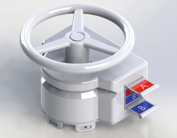
This will entail operators opening valves on the system in a specific sequence. However, as the sequence is critical, it is not just left up to the operator following the operating procedure document. In this case, each valve is fitted with a unique, specially designed key. Only when the correct valve is put into the correct position can the key be removed to open the next valve in the sequence. The key is designed so that it will only fit the correct valve in the sequence.
This process is repeated until all the valves are put into their correct position and in the correct sequence, resulting in a fool proof procedure for a highly critical operation. Once all the valves have been set, the final key taken from the last valve allows the operator to open the isolation valve. This then allows gas to be introduced to the system and the process becomes operational.
Let’s look at what these valves look like in real life. The examples shown are with kind permission of ISS Safety Systems Ltd (Figures 1, 2 and 3).

Source: ISS Safety Ltd.
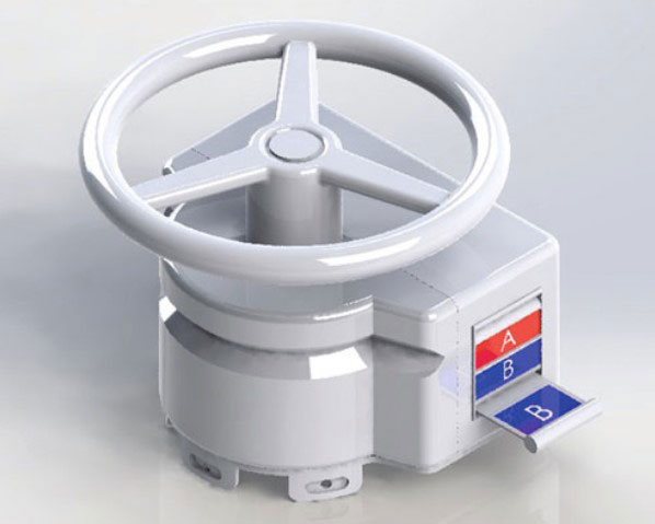
The control room will monitor the setting of the valves, and the CROs have the ultimate control of these valves, although they can be closed manually if required or by the Emergency Shutdown system (ESD) in the case of an emergency.
Source: ISS Safety Ltd.
Once all the valves are set and the isolator valve is opened, gas from the well is introduced into the system. At this stage of the start-up operation, the gas pressure is set to a low level and only increased gradually as per the start-up procedure document.
Constant checks will be made to the system to ensure nothing is amiss. This will include monitoring readings in the control room as well as watching and listening for leaks by the operators at the plant.
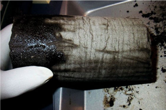
Source: ISS Safety Ltd.
This is the stage where hydrates (ice plugs) might form, and as a counter measure, methanol may be injected upstream.
Only when all optimum pressure levels, temperatures and flows have been established, can the line be regarded as being “online”. Furthermore, it is only when this level of operation is attained that the control room can take over the operations and run the operation automatically.
Shutdown
Shutting down a process can be equally as hazardous as start-up. Consequently, the personnel involved should work as a team from a predetermined operating procedure which will take into account all possible eventualities associated with shutdown.
In the case of our example of a gas production train on a gas producing installation, the procedure is undertaken in a deliberately slow manner. Each well (if there is more than one) is taken offline by closing its wing valve.
Once the gas flow has stopped, all the ancillary systems can be slowly shut down and isolated.
The production train is shut down and isolated by closing the valves in the reverse order to that in which they were opened. Again, the key system on each valve ensures the correct sequence is followed.
Looking at another example of shutdown, this time on a refinery, the same sources of hazard exist. In this case, the procedure will be undertaken in a number of phases, including the following:
- Cooling and depressurization of the process.
- Reducing the flow and process liquid levels.
- Removing any residual hydrocarbons.
- Inerting and gas freeing the system.
- Removing any corrosive and/or toxic materials from the system.
- Removing any water from the system.
- Blinding operations (the isolating of process pipework).
Over and above that, any fired heaters should be shut down, reducing the heat input into the process. The flow of product should be gradually reduced and eventually shut off. Any excessive pressure emanating from hydrocarbon gases should be released into the gas collecting system.
Hazards and controls associated with water and hydrates, their presence and removal
Water and hydrates – their presence and removal
The formation of hydrates (ice plugs) within a production process plant during start-up and shutdown was mentioned as a potential problem earlier in this chapter. Because this problem has the potential for serious consequences to evolve, it deserves to be discussed in greater depth.
A hydrate is formed when water is trapped within the oil or gas process and the conditions within the process allow it to freeze into a solid plug.
When the flow of product or the pressure of the product is reduced, this has the effect of reducing the temperature and it is at this point where the formation of a hydrate can occur if there is water within the system.
Hydrates can also be formed in pipelines which run across the sea bed. This is because temperatures at sea bed level can be low enough to freeze un-salted water which accompanies the oil and gas as it is extracted from the wells.
Some hydrates are made up of additional materials, as well as water, and these can form into sticky crystals which have the potential to grow into large ice plugs which can completely block a pipeline.
Water and hydrates – controls
To prevent hydrates forming in the first place, antifreeze (usually methanol or glycol) can be introduced into the process system so that it forms part of the product. This antifreeze is usually recovered later when the oil and gas arrives onshore, allowing the antifreeze to be reused.
Source: US Department of Energy.
However, using antifreeze is an expensive process, and an alternative means of control is the use of trace heaters along with insulation. Trace heaters are cables which run along the outside of the pipework and which apply warmth to the system. The escape of this warmth is reduced by the insulation applied to the pipe.
Removal of water
The removal of water from processed oil and gas can be achieved by a number of methods. Each has its own advantages and disadvantages.
The following techniques and technologies outline what means are available for removing water from oil and gas. We have also indicated their relative advantages and disadvantages.
Removal of water – gravity separation
Where the product is a mixture of oil and water and is allowed to stand for a while, water will naturally settle to the bottom, as the specific gravity of water is greater than oil. This can then be drained off.
The effectiveness of this system is dependent upon how long the system was allowed to stand before water is drained off, and whether the temperature is low enough to reduce the saturation point to an acceptable level. Lowering the saturation point ensures as much water as possible leaves the system.
Some types of oil have the characteristic of holding water in suspension rather than allowing it to settle at the bottom and separate out. In these cases, gravity separation is a less than effective option.
The main advantage of this system is the relatively low cost of operation.
The main disadvantage is that it only removes free water, and any emulsified water will remain in the product.
Removal of water – centrifuge (spin the oil clean)
This system uses the principle of centrifugal force and the fact that water has a different specific gravity from oil, and that difference allows this system to separate the two materials. The greater the difference in specific gravity between the oil and the water, the more effective the process is. Consequently, centrifuges work best on low specific gravity and low viscosity oils such as turbine oils, rather than other, heavier oils.
Centrifuge systems remove both free water and emulsified water, but their effectiveness will depend on how low the specific gravity of the oil is when the centrifuge process takes place.
The main advantage of this system is that it can, in the right circumstances, remove both free and emulsified water. It can also remove other heavier contaminants and has a comparatively high throughput compared with other technologies. Centrifugal separators are relatively cost-effective.
The main disadvantage of this system is that the capital cost is relatively high. Also, cleaning a centrifuge is a time-consuming task which has to be undertaken frequently.
Removal of water – absorption removal
Absorption removal is the process of using filters to absorb the moisture from product as the product passes through the filter. There are a number of different types of filter medium. Cellulose based filters are effective for removing small amounts of water. Also, as they swell quite noticeably when they do absorb moisture, they are a useful means of indicating the presence of water in the product.
Other types of filters have an outer wrap consisting of polymer and desiccants which can absorb both free water and emulsified water. They can also filter out solids.
The main advantage of absorption removal is that it is a relatively cost-effective means of removing small amounts of water.
The main disadvantage is that each filter has a limited capacity.
Removal of water – vacuum dehydration
The process of vacuum dehydration works on the principle that water boils at a lower temperature when it is at a lower pressure. Consequently, at 0,9 bar, water will boil at around 52 °C.
A vacuum dehydration unit reduces the pressure of the product within it. Air which has been dried and warmed is then passed over the product and the moisture is then transferred to the air from the product in the form of steam vapour.
The efficiency of the system is enhanced by increasing the surface area of the product as it is exposed to the warm air. This can be achieved by exposing the product in shallow amounts over numerous surfaces within the dehydrator.
The main advantage of this system is its ability to remove moisture to very low levels. It also has the ability to remove other impurities such as fuels and solvents.
The main disadvantages are its cost and relatively low flow rates.
Removal of water – air stripping
Air stripping is another form of vacuum dehydrator which works by mixing air, or nitrogen gas, with a stream of heated product within the air stripping unit. The gas then absorbs the moisture from the product and when the gas and product mixture is expanded, the gas separates from the product and takes the moisture with it.
The main advantage of this system is that it costs less to maintain than a typical vacuum dehydrator as it has fewer moving parts.
The main disadvantages are its cost and relatively low flow rates.
Removal of water – heating the oil dry
Some processes, because they run at elevated temperatures, are self-cleansing due to the fact that water naturally evaporates at these temperatures. However, these processes must be controlled effectively to avoid harm, particularly with mineral oils.
Compared to centrifugal and vacuum separation systems, heating the oil dry can be an effective means of removing water from a product.
Summary of methods of hydrate removal
The final decision as to which system of water removal is appropriate to any one process will depend on:
- The volume of product to be treated;
- The required level of moisture content in the final product.
If the level of moisture required in the final product is low but the saturation levels of the product prior to treatment are high, then more complex and expensive systems will be required.
Hazards and controls associated with testing, commissioning and hook up
Commissioning
The commissioning of a process plant involves undertaking tests on the plant prior to it going into production in order to determine that it will function adequately and safely. The commissioning process also includes training the people who will operate the plant as well as the control room staff who will oversee operations. Finally, it includes writing the operating procedure document.
During this commissioning period, when operating experience is at a minimum, the possibility of unforeseen events occurring cannot be eliminated. Consequently, all safety precautions should be reviewed prior to commissioning commencing. This is normally undertaken at the design stage of the plant and usually takes the form of a Hazard and Operability (HAZOP) study or an equally extensive and in-depth risk assessment.
The process of commissioning involves taking the plant through a number of phases, all of which have to be completed in a satisfactory manner before the plant can be handed over as fully functional and ready for operational use.
A typical sequence of phases undertaken during the commissioning process is set out below:
- The system configuration is checked (walking the line).
- The pipework and system integrity is checked.
- The instrumentation system is checked.
- All alarms are verified as working.
- All lines and vessels are flushed and cleaned.
- All ancillary equipment is inspected and assessed as to its adequacy.
- All instruments and vessels are calibrated.
- The start-up protocol is established.
- The shutdown protocol is established.
- Commissioning trials are undertaken.
- The plant is hooked up.
- The plant is handed over.
We will now take a look at each of these phases in a little more detail.
Commissioning – system configuration check (walking the line)
This phase is where all the pipework and connections are physically inspected to ensure their configuration is as it should be and they have been installed correctly.
This inspection is made against Engineering Line Diagrams (ELDs) also known as “as built” drawings. The inspection process also includes ensuring the plant and equipment are clean, empty and fit for purpose.
Commissioning – pipework and system integrity
This phase is where all the parts of the system are pressure tested to ensure there are no leaks or unexpected deformities. This is usually undertaken using hydrostatic testing techniques.
Hydrostatic testing is a system which tests the integrity of plant and equipment, including pipework, which will be subject to pressure under normal working conditions. It involves filling individual sections or components of the system with a liquid, usually dyed water, and then pressurizing that section or component. Pressure is then monitored to see if there is any unexpected deformity or loss of pressure. A loss of pressure would indicate a leak, and the fact that the water is dyed will help locate any leak.
Once all the sections and components have been individually tested, all the sections and components are connected and a test of all the flanged joints and couplings is carried out. This is carried out using nitrogen and a trace gas in order to detect any leaks.
Commissioning – instrumentation system check
This phase is where the system is checked against the Piping and Instrumentation Diagrams (P&IDs). A P&ID is a schematic drawing showing the physical sequence of equipment and systems, as well as how these systems connect.
Included in the P&IDs are:
- All the instruments, their location and designation.
- All the mechanical equipment with their names, numbers and functions.
- All the valves with their identification and function.
- All the piping with their sizes and identification.
- Any miscellaneous equipment such as vents, drains, sampling lines, etc.
- Start-up and flush lines.
- The direction of flow.
- Any interconnection references.
- All control inputs, outputs and interlocks.
- All computer control system inputs.
- Any identification references of components and sub-systems delivered by third parties.
Commissioning – verification of alarms
This phase is where all the alarm settings, microprocessor signals, hardware trips and all other instrumentation are checked to ensure they are set correctly and are functioning as required. The computer systems are also checked to ensure they are functioning properly and that information from all the field instruments is being relayed to the computer interfaces and is being displayed correctly.
Commissioning – flushing and cleaning of lines and vessels
This phase is where all the vessels and associated pipework are flushed through with water in order to flush away any contaminant material. The process is also aimed at ensuring there are no foreign items or materials within the system which may have been left behind at the time of construction.
Once the flushing operation has been completed, it may be necessary to dry the system completely, especially if the final process system is incompatible with water. This is done by venting warm, dry air through the system so that any residual moisture is evaporated away.
Commissioning – inspection and assessment of ancillary equipment
This phase is where all the ancillary equipment, such as:
- pumps,
- fans,
- heat exchangers,
- condensers,
- compressors, etc.
are tested to ensure they perform to their expected requirements.
Commissioning – calibration of vessels and instruments
This phase is where all the vessels and instruments are checked to ensure they have been calibrated correctly.
Commissioning – start-up protocol
This phase is where the procedure for starting up the installation from complete shutdown to full production is evolved and set down in writing. This phase also includes establishing all potential erroneous occurrences and providing guidance on the best and safest course of action on how to deal with each of them. This start-up procedure will form part of the “operating procedure” document.
This phase will also involve the training of all personnel involved in the operation of the system once it is handed over.
Commissioning – shutdown protocol
This phase is where the procedure for shutting down the installation from being in full production to complete shutdown is evolved and set down in writing. This phase also includes establishing all potential erroneous occurrences and providing guidance on the best and safest course of action on how to deal with each of them. This shutdown procedure will form part of the “operating procedure” document.
This phase will also involve the training of all personnel involved in the operation of the system once it is handed over.
Commissioning – commissioning trials
This phase is where the plant is started up, run for a predetermined length of time within specific parameters, and then shut down. This is so the plant can be proven to be operational. It is also an ideal opportunity to give some “hands on” training to the personnel who will be operating the plant once it is handed over.
Commissioning – hook up
This is the phase where the system is connected to – although isolated from until the initial start-up procedure is ready to be undertaken – its source of product (oil, gas, etc.). It also includes the system being connected to – but again being isolated from – the utilities needed to operate the system.
Commissioning – handover
This is the final phase of the commissioning process and involves handing over the responsibility for the plant, as well as the plant itself, to the operational department. All associated documents, drawings and procedures will also be handed over.
During the premier run of the plant, it is quite normal for representatives of the suppliers of the plant and/or equipment to be present or on hand.
REVISION QUESTIONS FOR ELEMENT 2 CONTINUED
Answer 1
Thermal shock is where a material is exposed to a sudden and significant change in temperature. This results in the material expanding at different rates within a limited area, causing a crack or failure.
Answer 2
- The gradual introduction of steam or warm product from a lower temperature base (i. e. not superheated steam at the outset).
- Thoroughly warming up the systems prior to use.
- Designing in expansion loops into the system, for example bellow pieces. These allow the pipework to expand with thermal change without compromising the integrity of the system.
- Using materials with greater thermal conductivity.
- Reducing the coefficient of expansion of the materials.
- Increasing the strength of the materials.
Answer 3
- The system configuration is checked (walking the line).
- The pipework and system integrity is checked.
- The instrumentation system is checked.
- All alarms are verified as working.
- All lines and vessels are flushed and cleaned.
- All ancillary equipment is inspected and assessed as to its adequacy.
- All instruments and vessels are calibrated.
- The start-up protocol is established.
- The shutdown protocol is established.
- Commissioning trials are undertaken.
- The plant is hooked up.
- The plant is handed over.