This article gives the important information about requirements to transport the cargo on the LPG carrier on the Danube river.
Summary
Wide use of the liquefied gases as alternative fuel for the European automobiles has caused significant interest to the special vessels, allowing to deliver the given dangerous cargo (propane-butane) from supplier Volga and Dnepr ports to the consumer (Danube ports) with the minimal losses of time, resources and cargo at reloading operations.
Marine Engineering Bureau had been given the task by the Bulgarian company “Bulmarket” to search for suitable river-sea navigation dry-cargo ship with about 1 000 t carrying capacity and subsequent conversion to about 2 000 m3 capacity LPG carrier for work on Danube port Ruse. Decision on re-equipment of an existing dry-cargo vessel has been connected to financial limits and necessity to have the required vessel in the shortest term.
The choice of high pressure tanks is caused by an available coastal infrastructure and vessel’s means. The most effective for chosen type LPG and capacity (Danube limits for dangerous goods) are horizontal cylindrical tanks in hold and on a deck, that has allowed the number of required tanks to be reduced to six (4 hold and 2 deck).
A feature of the vessel’s structural design was the necessity of maintenance of local strength and survivability of side structures in a case of collisions, with the purpose to prevent damage of cargo tanks and cargo pipelines.
Introduction
The first transportations of liquefied gas (LG) on sea were carried out on converted tankers and dry-cargo ships in the period from 1929 to 1952 (with a break on II World War). The first special built vessel for transportation of LG with capacity of 670 m3 was built in 1953.
The first Soviet Union domestic gas carrier also has been received in 1960 as a result of modernization from a tanker of “Kazbek” type by installation of 21 railway tanks on a deck with total capacity of 1 070 m3.
Further LG transportations were carried out within the Baltic Sea by vessels of “Kegums” type with capacity of 2 040 m3 (four spherical tanks) and “Jurmala” type with capacity of 12 000 m3. Other domestic vessels had essentially large carrying capacity and dimensions and worked on continent and on the USA ports.
However now in Fleets of the ex-USSR countries, there are no vessels for LG transportation.
The appreciable part of modern LG transportations falls at:
- South Korea;
- Japan;
- China;
- Taiwan;
- India;
- and also the USA and a number of European countries.
In the beginning of 2000-th 587 from 1 058 gas carriers had deadweight less than 5 000 t and, as a rule, intended for transportation of the liquefied petroleum gases (LPG) under pressure. Mean age of such vessels has exceeded 20 years.
The first designs of special vessels for LG transportation on inland waterways (IWW) were made in the USA in 1950. Development of river gas carrier projects in the USSR was carried out at the end of the 1950’s – beginning of the 1960’s.
Wide use of LG as alternative fuel for the European automobiles has caused significant interest to the special vessels, allowing delivery of the given dangerous cargo from the manufacturer (in particular, ports on Volga and Dnepr) to the consumer (for example, ports of Danube) with the minimal losses of time, resources and cargo at reloading operations.
Similar vessels should meet dimensional restrictions (on length, width, draught, air draft) and sluices, channels, navigable ways of IWW Russia, Ukraine, the Lower and the Middle Danube regions and to be strong enough and seaworthy enough for operation in the Black and Azov Sea areas performing all of the requirements of survivability in emergencies required by the International agreements.
Analysis of existing fleet gas carriers has not identified vessels having such characteristics.
Statement of a task
The Customer – Bulgarian company “Bulmarket” set a problem to the Marine Engineering Bureau to search for a suitable dry-cargo ship and its subsequent conversion into an LPG (propane-butane) carrier of the mixed river-sea navigation with carrying capacity about 1 000 t for operation on the Danube port of Ruse. In general, such conversion requires installation of high pressure cargo tanks and corresponding re-equipment of the:
- hull,
- systems,
- fire-protection structures,
- other elements of a vessel.
Decision on re-equipment of an existing dry-cargo vessel has been connected to financial limits and necessity to have required vessel in the shortest term.
The choice of LG transportation (under pressure) has been caused by an available coastal infrastructure and vessel’s means. Alternative transportation with simultaneous cooling requires ship means for cooling (refrigerator installation, compressors, condensers, additional armature) and essentially more powerful diesel engines – generators at though the weight of tanks in that case could be approximately twice less. Besides there was a necessity for a corresponding coastal infrastructure (installations for gas liquefy, isolated tanks for storage and isolated pipelines for transferring) which in ports assumed for work is not present also creation demands essential capital investments and time.
Such decision is traditional for conversion of reception vessels for LG transportation – simple, rather cheap and does not demand insulation of tanks and systems, but leads to appreciable weight of tanks because of increased pressure and to loss of useful space in the vessel since internal tanks should be from positions of the minimal weight either cylindrical, or spherical.
Technical and economic analysis shown, that application of horizontal cylindrical tanks in holds and on deck is the most effective for the The Liquefied Gas Tanker typeschosen type and carrying capacity of LPG carrier. Horizontal tanks also allow reduced number of required tanks to six (four in holds and two on deck), and as result cut down expenses on armature, materials and manufacturing and having improved operating ratio of volume of cargo space.
Requirements to overall dimensions of the vessel
Designing of a vessel of the mixed river-sea navigation (RSN) is always a compromise between maintenance of the set carrying capacity (usually greatest possible) in conditions of the limited dimensions and requirements to seaworthiness – strength and damage stability. The analysis of dimensional restrictions, imposed on researched vessel by expected areas of operation has been carried out (see Table 1). IWW class is specified according to the European classification of IWW (the United Nations EEC resolution No. 30, November, 1992), wave zone.
Statistical data from on changes of depths on the Lower and Middle Danube are shown in the Table 2. For researched vessels the dimensional parameters connected to the necessity to operate on the Danube were: draught – not greater than 3,00 – 3,10 m, on width – not greater than 12,0 m, on length – not greater than 110 m.
The class of a vessel after conversion should allow normal operation in sea conditions of the Black and Azov seas. The analysis of wind – wave conditions and actual distances between places of a refuge has shown that the Russian Maritime Register of Shipping (RS) class IIISP (the permissible height of a wave of 3 % probability h3 % 3,5 m) is sufficient. However, in view of special purpose of the vessel, the decision on assignment of higher class was accepted.
Read also: Cargo Containment Systems of LPG and LNG
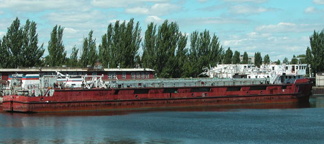
A dry-cargo vessel of the project 191 “Dneprovets” type with initial Russian River Register class “O-pr” (h3 % = 2,0 m) had been chosen as most suitable under the given restrictions. Thus this choice besides the decision of a problem of change of purpose required to resolve a problem of increase in a class (the overall and local strength) up to RS class IISP (h3 % = 6,0 m) by reinforcements of hull structures. The basic characteristics of the vessel before and after conversion under the 001RSG01 project of the Marine Engineering Bureau are given in the Table 3.
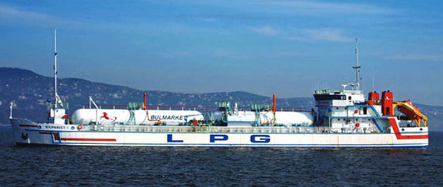
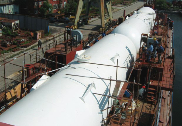
A dry cargo vessel of the 191 project in initial condition is shown on the Fig. 1, and after conversion by the project 001RSG01 LPG carrier “Bulmarket-1” is shown on the Fig. 2
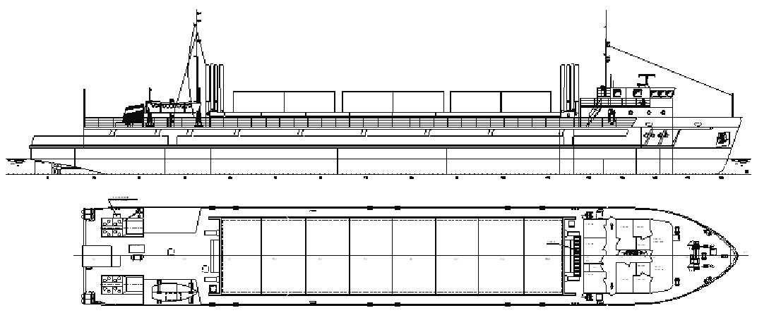
The general arrangement of a vessel of the 191 project in an initial condition is shown on the Fig. 3 and after conversion by 001RSG01 project as LPG carrier “Bulmarket-1” is shown on the Fig. 4.
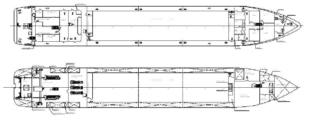

For maintenance of transportation about 1 100 tons concerning a light cargo with density of 0,52-0,60 t/m3 the basic decision on increase in length and volume of a cargo area was accepted due to move deckhouse from fore to aft (also correspond to LPG carrier’s special requirements), with the equipment on its place of additional cargo space (in hold from Fr. 113 to Fr. 127, on a deck – from Fr. 113 to Fr. 136). Cargo tanks have been placed in pairs in two holds Fr. 127-80 and Fr. 36-80 each in volume of 370 m3 and two on the trunk deck with 298 m3 (aft) and 360 m3 (forward) in volume.
Requirements to gas carrier of the mixed river-sea navigation
At designing of RSN vessels for transportation of dangerous cargoes on usual restrictions requirements of the corresponding international agreements regulating such transportations also are imposed.
The RSN – gas carriers fall under simultaneous action of requirements of the International Gas Code (Code), as sea vessels, and requirements of Rules of transportation of dangerous cargoes on internal waterways of Europe (ADN), as river vessel that makes their design unique in comparison with usual sea gas carriers.
On classification of the Code given vessel it is related to type 2PG with internal tanks type C, according ADN – the tanker type G.
The general arrangement of a vessel, arrangement of transverse and longitudinal watertight bulkheads are determined both ADN requirements, and requirements of the Code to flood ability and damage stability, are given in tab. 4 and 5.
In particular, for RSN gas carriers the length of side and the bottom design damages are greater, since probability of contact with ground, quays and other vessels in the river is essentially higher. Besides for the given vessel of the requirement of the Code to stability of the damaged vessel are checked at an arrangement in any place on length of a vessel between bulkheads of subdivisions into compartments (i. e. one compartment floodability), ADN requirements – at an arrangement of damages to any place on length of a vessel (i. e. two compartment floodability, except Engine room).
Minimal permissible distances for access for maintenance to cargo tanks and systems, and also to the other compartments in cargo area have essential influence on architecture and hull structure of the vessel.
Moving the deckhouse from the fore to aft position has led to usual for LPG to architectural – constructive type, and maintenance of appropriate protection of crew in emergencies.
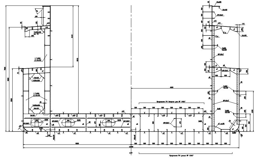
Because of shortage of cargo volume, it was necessary to remove inner side’s structures in cargo area of the vessel. For single-hull LPG carriers determining requirement is ADN requirements to local strength and survivability of side hull structures at collisions with the purpose to prevent damages of cargo tanks and cargo pipelines. Calculation is made on absorption of energy 22 МJ of transverse collision a river vessel with vertical stem.
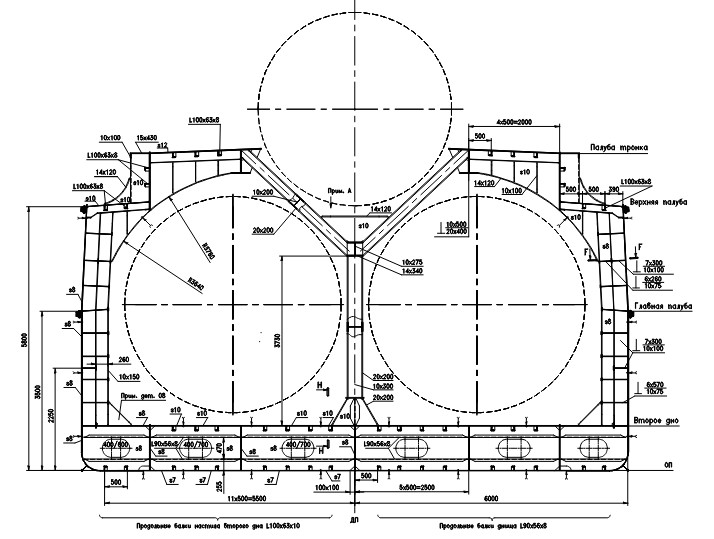
For creation of such side structure it was required to install side stringers with vertical space distance of 600 mm – see midship section of the vessel before and after conversion on the Fig. 5.
Designing of cargo tanks
Essentially important problem at designing LPG is creation of optimum on weight tanks for LG transportation for since it makes up to 40-50 % from the hull weight.
For cargo tank’s structure determining requirement is requirements of the Code to strength of tanks at any probable loadings in operation and their real combinations; a test pressure, the additional loads connected to an opportunity of increase of calculation pressure of vapour during berthing in port; loads at a static roll in 30°; absorption of energy of collision (without direct contact to a ramming vessel).
At designing of internal tanks for LG strength analysis has been executed with the help of a finite element method in plate idealization of tensely deformed condition of their structures:
- shell,
- frames,
- support structures,
- manholes,
- branch pipes,
- local reinforcements.
Cargo tanks represent cylindrical surface of rotation with spherical ends. Designing of tanks was made according to the Code and ADN requirements.
The basic characteristics of tanks are given in the Table 6. The maximal volume of tanks was regulated by ADN requirements and should not exceed 380 m3.
Four pairs of side, top and bottom supports have been provided in their structures for prevention of displacement of cargo tanks. Side support intended for react on vertical loads, the loads arising at emersion of the tank, longitudinal loads. Longitudinal loads were reacted by one pair support located closer to the centre of the tank in direction of force action. The top and bottom supports intended only to react on transverse loads.
Design of supports has been executed so that it did not interfere with moving of elements of tanks at their expansion under influence of internal pressure.
A reserve on corrosion wear is accepted equal 0,8 mm. There are 6 tanks installed on the vessel:
- four tanks Type 1 in holds,
- one tank Type 2,
- and Type 3 on a trunk deck,
it is made from steel with yield stress not less than 315 МPа.
The finite element’s models (FEM) of cargo tanks included actually the tank and support structures (see Fig. 6) with a view of reduction of volume of calculations presence at the tank of two planes of symmetry is used. FEM was built in the Cartesian system of coordinates. Shell eight-central elements were used at creation of FEM. The grid of final elements was built with use of the generator of automatic splitting, thus the maximum size of the side of a final element did not exceed 200 mm.

Conversion of the vessel
As a result of the analysis the Marine Engineering Bureau developed the project of conversion. The following basic works were provided:
- Dismantle existing inner sides in the area of from the Fr. 36 to Fr. 116, transverse bulkheads on Fr. 39, 113, 116, 135, cargo hatches coamings in the area of from the Fr. 39 to Fr. 113; insulation, bulkheads, bulwark, and also forward deckhouse (all about 165 tons).
- Installation of side shell between the Main and the Upper decks with extension of the Upper deck to the transom, increasing height of forecastle, aft lengthening with raised transom, bilge keels, creation of side stringer systems in cargo area, installation of new watertight bulkheads on the Fr. 80 and 127, new double bottom in the area of from the Fr. 116 to Fr. 135; new structures of the 1st tier aft deckhouse, six internal cargo tanks with the fundaments in holds and on the trunk deck (see Fig. 7); trunk decks and casings of the deck tanks; to move existing deckhouse from fore to aft (on the new 1st tier aft deckhouse), installation of log and sounder trunk (all about 808 tons, from them about 500 tons has fallen to cargo tanks and their fundaments).
- Dismantle of cargo hatch covers and a part of other devices (all about 82 tons).
- Modernization of the anchor gear with increase in capacity of bow chain lockers; installation of tanker type free-fall life boat with davit and life rafts; a rescue boat with corresponding davit.
- Installation of ladders shafts inside living and service compartments with A-0 type fire-resistance with installation self-closing doors A-0 type; ladders shaft of an emergency exit from Engine Room to execute as A-0 type with installation of self-closing door A-0 type; replacement of all external doors on steel water-gastight with 380 mm height of coamings.
- Modernization of port lights and wheelhouse windows; increase in height of air pipes, vents and door’s coamings; closing of outside scuppers in the Main deck.
- Moving of the emergency diesel – generator from the Main deck to the Upper deck (Freeboard deck); installation of CO2 fire extinguisher system in the Engine Room, diesel – generator compartment, emergency diesel – generator room, cargo compressors and pumps rooms; 2 fire pumps of 63 m3/hour capacity at pressure 0,8 МPа each; the emergency fire pump of 60 m3/hour at pressure 0,7 МPа.
- Additional equipment, special devices and systems according to the project of conversion of the vessel in gas carrier.
In Table 7, hull structure was the major share of removed and installed weights.
Conclusion
Experience of the Marine Engineering Bureau in conversion of dry cargo vessel in LPG carrier of mixed river-sea navigation has shown, that such type of vessels intended for transportations of cheaper and ecologically safe fuel for automobiles directly to European consumers is necessary and economically justified.
The basic results of research are the following conclusions:
- The most effective type of vessel for conditions of transportation is an LPG type gas carrier with about 1 000 t carrying capacity.
- The most effective type of tanks for the chosen type of a vessel and its carrying capacity are horizontal cylindrical tanks in hold and on a deck.
- Main dimensions of the vessel are determined by operating conditions on the river Danube: draught – not greater than 3,00-3,10 m, on width – not greater than 12,0 m, on length – not greater than 110 m.
- The class of a vessel is determined by wind-wave conditions of operation at sea (permissible IIISP, the authors recommend IISP).
- General arrangement of the vessel, arrangement of transverse and longitudinal watertight bulkheads are determined both ADN requirements, and requirements of the Code to flood ability and damage stability, stated above.
- Essentially the important design problem is creation of optimum on weight tanks for LG transportation that demands application of modern settlement means, such as programs of calculation based on finite element method in plate idealization.
- For single-hull LPG carriers the determining requirement is ADN requirements to local strength and survivability of side hull structures at collisions with the purpose to prevent damages of cargo tanks and cargo pipelines.
Construction of vessels – gas carriers mixed the river – sea has real prospect for the ship-building industry and provides with the minimal expense, export transportation of alternative automobile fuel for consumers in East and the Western Europe on system Danube – Main – Rhine directly from domestic manufacturers.
Authors