The Gas Control Station operational workflow guidelines are crucial for ensuring the seamless and safe management of natural gas transport. At the gas control station, every phase of operation is meticulously planned and executed, from initial system checks to emergency responses. Before starting operations at the gas control station, a comprehensive inspection of all equipment and safety systems is conducted to ensure everything is in optimal condition. During the startup phase at the gas control station, operators carefully increase pressure and flow rates while closely monitoring all parameters to prevent any abrupt changes that could disrupt the system. Utilizing advanced systems, the gas control station operators can continuously oversee critical metrics, ensuring optimal performance and making real-time adjustments as needed.
During routine operations at the gas control station, adherence to scheduled maintenance and regulatory compliance is essential. Detailed logs of all activities at the gas control station are maintained to provide a clear record of operational status and any incidents. In case of emergencies, the gas control station guidelines include clear shutdown procedures and communication protocols to ensure a swift and coordinated response. Post-operational procedures at the gas control station involve thorough debriefings and reviews of collected data to identify any areas for improvement. By rigorously following these guidelines, the gas control station can maintain high standards of safety and efficiency, protecting both their personnel and infrastructure.
Cargo Control Room
Initially the cargo control room of an LNGC was located above the deck within the cargo area aft of the loading crossover. The cargo control room was fitted with a monitoring and control systems for continually monitoring key parameters in the LNG cargo system and also acting as a control facility when LNG Cargo Handling Systems and Their Operationshandling LNG in the system.
This cargo control room was normally unmanned during the voyage. However, equipment within it continually monitored sensor signals for cargo tank pressures and temperatures, cargo levels, liquid nitrogen tank levels and temperatures and presence of liquid in the holds. Whenever any of the signals indicated a condition beyond pre-programmed safe limits, the cargo console generated an alarm condition, which activated audio/visual alarms at the console and at the repeater panel in the
wheelhouse.
The cargo control console was manned during loading and unloading operations. During these operations, the console provides control for the operation of the ballast and cargo systems. It also monitors and displays the status and condition to aid in operation of the system by the operator.
Today’s ships are fitted with a Centralized Administration and Control Center (CACC) in the deckhouse. Normal control of all cargo and machinery operations is carried out from here.
The ship’s Integrated Automation System (IAS) is used for all normal and some emergency operations including monitoring, planning, control and alarm functions. The main CACC console is split into cargo (port side) and machinery (starboard side) sections.
A computer room is used for administrative functions. Here the SMS (ship management system) terminals etc are installed.
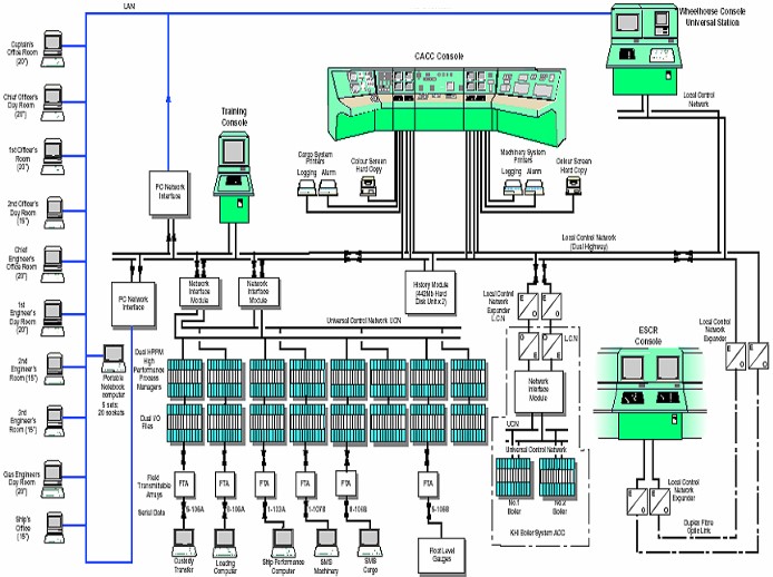
A Cargo Hard Mimic board may be located on the aft bulkhead to the rear of the cargo console. It indicates valve positions but does not allow control. Figure 1 shows a typical CACC arrangement.
Integrated Automation System (IAS)
Introduction
In general, the Integrated Automation System (IAS) controls and monitors almost all systems and equipment on board. The functions of the IAS are as follows:
- System monitoring.
- System control manipulating and operation.
- Alarm handling, summary and acceptance.
- Data logging and trending.
- Data interfaces to other systems.
- Control of the extension alarm system.
- Operation planning and control.
- Data output to the PC based LAN.
General Considerations
The following is the description of a system actually installed on a MARK III System: Hull and Deck Components for Marine VesselsMARK III membrane type LNGC recently built and it has been generally taken from the ship Operation Manual. Of course IAS are in continuous evolution and even sister ships built by the same shipyard may have different IAS based on the designer and the vendor of the automation system and on the continuous alteration/improvement that each vendor does on its own product. However, it is felt that a general description of a particular system can be taken as an example on what are the main functions and performances that an IAS arrangement for all today’s LNGC’s should assure.
The IAS Universal Control Stations
The IAS system universal stations are workstation processors with a local keyboard and single or dual monitors, which are located in:
- CACC: Dual universal stations on port side for cargo.
- Training console: Single universal station for both cargo and machinery operations.
- Wheelhouse: Single universal station for machinery operations.
In addition there are:
- CACC: Dual universal stations on starboard side for machinery.
- ECR: Dual universal stations for machinery operations.
Both sets of mimics and functions can be accessed from either universal station. There is a QWERTY keyboard fitted under a cover, which can be accessed via a supervisor level keyboard.
IAS Universal Control Station Operation
The universal station is the main operator interface to the system. It is one of the modules on the Local Control Network. Each station can communicate with other modules on the LCN and with connected devices on the Universal Control Network (UCN). Figure 2 shows the IAS cargo operation console.

The universal station provides a single window to the entire system, whether the data is resident in one of the LCN modules or in one of the devices on the UCN. A single station can be used by an operator to access the following functions via displays, mimic diagrams, or trending and diagnostic displays:
a) SYSTEM AND PROCESS OPERATION FUNCTIONS
- Monitoring and manipulating operations.
- Display of current alarms, acceptance of alarms and summary display of all current alarms.
- Displaying and printing trends, logs, journals.
- Monitoring and controlling system status and diagnostics.
b) OPERATOR KEYBOARD AND TOUCH SCREEN
Each universal control station has an operator keyboard for normal operation. The CRTs have a touch screen overlay for operator input.
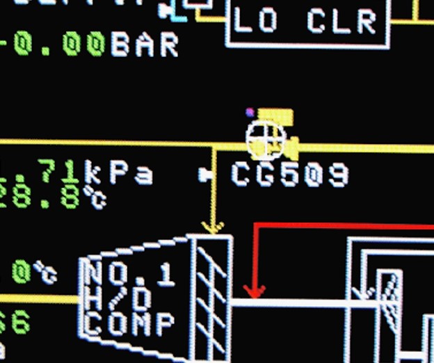
The touch screen control is an arrow-type pointer, which can be moved around the screen (see Figure 3).
c) DISPLAY LAYOUT
The top two lines are reserved for the integrated automation system, where new alarms, any system prompts and error messages are displayed. The date and time are displayed at the right hand side.
The schematic display title is indicated at the top of the graphic display. The graphic display is composed of pipelines, pump or valve symbols, numerical values etc.
The bottom three lines of the display are reserved for the Change Zone. This area is used for manipulating controllers, pumps and switches, which appear in this area when the operator selects the desired object on the graphic display. If no object is selected, the change zone displays system titles that are available for selection.
d) OPERATION – DIRECT KEYBOARD
There are several levels at, which the user can access functions. The main ones are listed as follows:
- Directly call up information about the status of system components.
- Directly call up process displays at several levels of detail.
- Move between different displays at the same level of detail.
- Select items on a particular display to be manipulated.
- Control the process set-point.
- Enter both alpha and numerical data.
e) OPERATION –TARGET SELECTION
By selecting items from the graphic display their status can be altered. Pumps can be started and stopped, placed on auto or manual and standby status altered. Valves can be manually opened and closed and placed on auto and manual. Process set points can be altered.
When it is positioned over a control element, it will change to a flashing cross hair type pointer. Touching this will activate the control function within the change zone (see Figure 4).
f) GROUP AND DETAIL DISPLAY
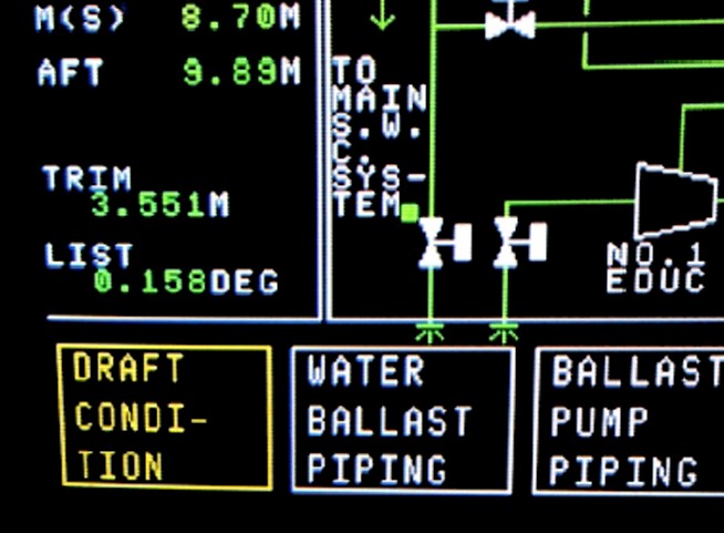
These show groups of parameters and allow the operator to take actions. They are selected from the yellow boxes in the change zone for certain schematics or can be selected by entry of the group number from the GROUP key. These are updated at 4 second intervals or 1 second when the FAST key is pressed.
The graphic displays can indicate numeric values and conditions and certain valves etc can be controlled from the touch display (see Figure 5).
g) GROUP TREND DISPLAYS
If one or more group parameters is selected and TREND key is pressed, a trend graph as shown in Figure 6 is displayed.
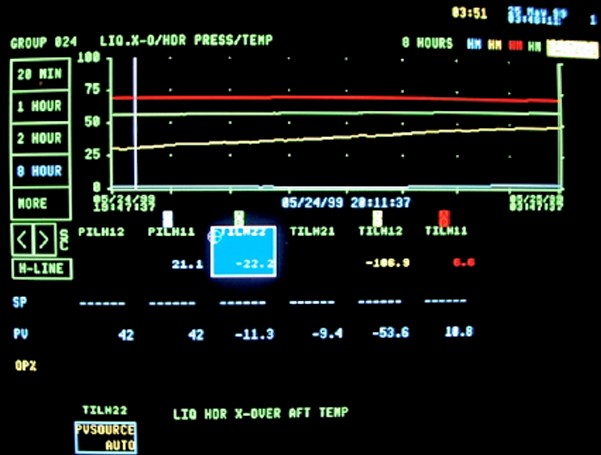
Variable scaling and time window step back/forward may be selected using the 20 min-8 hour box and the R-axis, C-line and H-Line boxes.
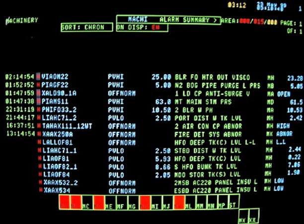
h) THE AREA ALARM SUMMARY DISPLAY
This lists up to 100 of the most recent alarms. Twenty of such alarms can be listed on each of five pages of this display. In addition, all units assigned to the station are represented at the bottom of the screen by targets for calling up the unit alarm summary displays. Alarms may be acknowledged on the top line of the screen or the display page (see Figure 7).
i) TIME MANAGEMENT
The IAS operates with dual time data. One is the system’s standard time, which could be GMT and the other is the ship’s time supplied from the ship’s chronometer. The ship’s time is used for alarm summary displays, status changes and report print outs. Standard time is applied to trend data and other printouts.
j) ALARM MANAGEMENT
The IAS initiates alarms from various processes by analogue or digital signals such as temperature high, level low, pressure high, etc. It also initiates alarms for abnormalities in the integrated automation system itself.
k) ALARM PRINTOUT
The historical alarm information is printed out on the alarm printer with reference to time.
The alarm printout provides the time that the alarm occurred, time the alarm was acknowledged and the time the process recovered from the alarm situation.
The red printout signifies that the channel/point has gone into alarm; the black when it has returned to normal.
The alarm set point is indicated and also the current value on the alarm line.
l) FAST ALARM FUNCTION
The fast alarm function is a high speed scanning function for finding out the cause of any trip. The data is recorded on the hard disk of the history module (HM) automatically. Time resolution is to within 20 ms. The operator can print recorded fast alarms if necessary. Fast alarms selected can be displayed on the screen and printed in sequence.
m) DATA LOGGING
The IAS provides a data logging function. It can produce a fixed time report, which is printed out automatically in accordance with a selected time interval. It will also print out a demand report in response to the operator’s request on the system operation display.
Other IAS Components
a) HPPM
High Performance Process Managers, which convert input analogue signals to digital and output control digital signals and analogue signals. These are linked by a dual data bus Universal Control Network over, which all data signals are exchanged. They are located in the APM cabinets in the ESCR and the electric equipment room.
b) FTA-SERIAL INTERFACES TO OTHER SYSTEMS
FTA’s, (Field Transmittable Arrays) manage serial data exchange with other systems and devices are used. These are linked to the HPPMs located in the APM cabinets in the ESCR and the electric equipment room.
The FTA’s provide an interface to the following other systems:
Cargo
- CTS Custody transfer system.
- LC Loading computer.
- FLG Float level gauging.
- SMS (cargo) Shipboard management system.
Machinery
- SPM Ship performance monitor.
- SMS (machy) Shipboard management system.
c) NETWORK INTERFACE MODULES
They link the Universal Control Network to the Local Control Network (LCN). This in turn links all the universal stations, the PC network Interface and the History Module. The Network Interface Modules also link the Boiler Control System to the IAS.
These network interface modules are located in the APM cabinets in the ESCR and the electrical equipment room and in the control consoles.
The universal control network uses fiber-optic transmission to link the ESCR console and the boiler control sub-system to the main universal control network.
d) HISTORY MODULE
The history module is a dual hard disk unit for data storage. It communicates with all modules on the local control network and any process connected device on the universal control networks.
It stores process and system information as below, which can be displayed or printed at the universal station. All analogue input data is recorded on the hard disk of the history module for 168 hours, automatically. The operator can call up any sets of data on the group trend display.
- Continuous process history.
- Sample data.
- Averages.
- Event journals.
- Process events.
- System events:
- Sequence of events (fast alarms).
- Active system files.
- Graphic display abstracts.
- Database checkpoints.
- User files.
- System configuration files.
- Static system files.
- Loadable software images (mimics).
e) VALVE POSITION CONTROLLER
The valve position controllers have two operation modes for manipulating the remote control valves.
Auto Mode
The system outputs open/close signals by comparing the requested valve position and the valve position feedback. The requested valve position is set by entry of a set point value.
Man Mode
The operator can control the open/close signal directly.
f) SENSOR MONITORING
The IAS monitors the process value of the analogue inputs. If the input fails, the system will indicate a sensor abnormal condition. Out of range inputs are highlighted.
g) TRAINING MODE
The IAS provides a training mode for the operator to study and familiarize the universal station operation for control and monitoring. The training mode is processed in the Universal Station, Network Interface and Advanced Process Manager Modules.
Cargo Part Displays and Operation Planning
In addition to the display of real time data for control and monitoring on the schematic screens, the IAS includes comprehensive operation planning, operation flow, line-flow and operation guidance schematics for most normal and out-of-service operations.
Line flow schematics indicate the position of the valves required and the flows in each line only.
The operation flow mimic schematics are a sequence chart showing the stages in each operation. Boxes allow access to group control operations and also monitoring schematics.
Line-ups are a quick reference to indicate the valve settings. Valves can be controlled via this schematic so that they correspond to the required settings before the operation proceeds. In each case, the color of the block after setting should correspond to the color of the required setting (right hand) block.
Personal Computer Network
The personal computer network interface is composed of a global user station.
A Local Area Network (LAN) of a number of PCs is connected to the LAN. Current data is updated in the personal computer network interface and stored in the real time database that can be accessed easily by the PCs allowing any monitoring and control schematic display to be set up and viewed within a DOS sub-window on the PC screen.
No control functions are accessible via the personal computers.
Extension Alarm System
An alarm extension Features and Functions of Integrated Alarm Systemalarm system is provided for the cargo and machinery systems. All alarms detected by the integrated automation system are sent to selected extension alarm panels located in the officers’ cabins and the public spaces.
Flow Mimics
Cooldown of Cargo System on the Liquefied Gas CarriersThe cargo system part of the IAS is configured so that the user is provided with guidance in executing most operations. The IAS has pre-programmed mimics, which allow the user to:
- Select an operation from the Operation Index.
- Select an Operation Plan.
- Select the Operation Flow. This mimic shows in algorithm form, the sequence of processes within an operation.
- Select the Operation Monitor for the operation. This is a mimic, which shows the process variables, allows control and using the change zone, allows set-points to be monitored and varied.

- The Society of International Gas Tanker and Terminal Operators (SIGTTO). Liquefied Gas Handling Principles on Ships and in Terminals (LGHP4) / 4th Edition: 2021.
- The international group of liquefied natural gas importers (GIIGNL). LNG custody transfer handbook / 6th Edition: 2020-2021.
- American Gas Association, Gas Supply Review, 5 (February 1977).
- ©Witherby Publishing Group Ltd. LNG Shipping Knowledge / 3rd Edition: 2008-2020.
- CBS Publishers & Distributors Pvt Ltd. Design of LPG and LNG Jetties with Navigation and Risk Analysis / 4th Edition.
- NATURAL GAS PROCESSING & ITS ENERGY TRANSITION ROLE: LNG, CNG, LPG & NGL Paperback – Large Print, November 14, 2023.
- American Gas Association, Gas Supply Review, 5 (February 1977).
- The Society of International Gas Tanker and Terminal Operators (SIGTTO). Ship/Shore Interface / 1st Edition, 2018.
- Department of Transportation, US Coast Guard, Liquefied Natural Gas, Views and Practices Policy and Safety, p. IV-3.
- Department of Transportation, US Coast Guard, Liquefied Natural Gas, Views and Practices Policy and Safety, p. IV-4.
- Federal Power commission, Trunkline LNG Company et al., Opinion No. 796-A, Docket No s. CP74-138-140 (Washington, D. C.: Federal Power Commission, June 30, 1977).
- Federal Power Commission, Final Environmental Impact Statement Calcasieu LNG Project Trunkline LNG Company Docket No. CP74-138 et al., (Washington, D. C.: Federal Power Commission, September 1976).
- Federal Power Commission, «FPC Judge Approves Importation of Indonesia LNG».
- OCIMF, ICS, SIGTTO & CDI. Ship to Ship Transfer Guide for Petroleum, Chemicals and Liquefied Gases / 1st Edition, 2013.
- Federal Power Commission, «Table of LNG imports and exports for 1976», News Release, June 3, 1977, and Federal Energy Administration, Monthly Energy Review, March 1977.
- Office of Technology Assessment LNG panel meeting, Washington, D. C., June 23, 1977.
- Socio-Economic Systems, Inc., Environmental Impact Report for the Proposed Oxnard LNG Facilities, Safety, Appendix B (Los Angeles, Ca.: Socio-Economic Systems, 1976).
- «LNG Scorecard», Pipeline and Gas Journal 203 (June 1976): 20.
- Dean Hale, «Cold Winter Spurs LNG Activity»: 30.