Learn the efficient procedures for cooling down cargo system in LNG carriers, covering both membrane and Moss type tankers. Explore step-by-step instructions and operational insights to ensure safe and effective cooldown processes, enhancing operational efficiency and safety standards.
Reference: SIGTTO “LNG Shipping Suggested Competency Standards”, Sections:
1 Have an awareness of the procedures for cooling down the cargo system:
- different cool down procedures required for different tank types.
2 Know and understand the procedures for cooling down the cargo system:
- line up and supply of LNG from shore to cargo tanks;
- tank cool down procedure and monitoring requirements for:
- membrane tank type;
- spherical tank type line cool down procedure;
- reason;
- implementation;
- final line temperature requirement at end of cool down.
- location and use of spray nozzles;
- cargo tank temperature gradient requirements during cool down;
- control of LNG flow rate from shore;
- control requirements for cargo tank temperature and pressure;
- final tank condition requirements regarding temperature, vapour pressure and surrounding insulation or cofferdams;
- use of high duty (HD) compressors for pressure control:
- line up;
- start requirements regarding cargo tank pressure;
- operation and control of HD compressor in manual and automatic mode;
- automatic control requirements;
- procedure for starting 2nd HD compressor.
- cofferdam heating system;
- nitrogen system demand (membrane containment systems);
- hold space pressure control (Moss type containment systems).
Overview
Cooldown is the process that brings the cargo containment system to a temperature that does not cause excessive boil-off during loading and prevents thermal shock to the cargo containment system. This normally follows immediately after completion of the gassing-up operation.
The cooldown operation is achieved by introducing LNG through the spray rail at the top of each tank. This allows the LNG to vaporise at the spray nozzles and cold vapour enters the tank.
Once the cargo tank cooldown is almost complete, the liquid manifold crossovers, liquid header and loading lines are then cooled. Any excess vapour generated is returned to the terminal, using the High Duty Compressor(s) on the Liquefied Natural Gas CarriersHD compressors, via the vapour return line.
A controlled cooldown rate, adhering to the manufacturer’s instructions and ship’s cargo operating manual, is essential to avoid damage to the primary barrier and overcome problems such as:
- excessive stress induced in the pump tower or trellis;
- prevention of vapour generation exceeding the capabilities of the HD gas compressors at any time during the process;
- structural deformation to the insulation arrangement being caused by non-uniform contraction;
- poor maintenance of the pressures in the insulation spaces within the operating parameters of the N2 generating plant and associated systems. In the initial stages of cooldown, pressures in these spaces can collapse, slowing down the whole procedure. On a membrane ship, ensure that the 2nd N2 generator is available as there will be substantial N2 consumption.
On membrane type LNGCs, cooldown continues until minus 130 °C (-130 °C) is achieved. On 140 000 m3 membrane LNGC, cooldown takes approximately 10 hours from +40 °C (+40 °C) to -130 °C (-130 °C).
On Moss type LNGCs, cooldown is continued until minus 115 °C (-115 °C) is achieved at the equatorial ring. On a 135 000 m3 Moss type LNGC cooldown takes approximately 24 hours from +40 °C (+40 °C) to -115 °C (-115 °C).
Hovewer, the cooldown rate should not exceed 10 °C per hour on a Moss type ship.
Membrane type LNGCs – preparation for tank cooldown
Reference should be made to the GTT approved cooldown documentation and cooldown curves appropriate to the specific LNGC.
Preparations should include:
- prepare the cofferdam steam or gycol heating system as appropriate;
- prepare the records for the cargo tank, secondary barrier and inner-hull steel temperature readings;
- check that the insulation space N2 supply system is in automatic operation and can supply the additional N2 necessary to compensate for the initial pressure drop experienced as the primary space atmospheres collapse;
- before cooling, raise the N2 pressure inside the primary insulation spaces to 8 mbar as extra compensation for the inevitable initial pressure drop;
- ensure the buffer tank is maintained at maximum operating pressure throughout the procedure;
- check that the gas detection system is in normal operation;
- prepare the N2 generating system for maximum output;
- prepare both HD compressors for use.
Cargo tank cooldown procedure (membrane)
Vertical thermal gradients within the tank walls of membrane containment systems are not a significant limitation on the rate of cooldown.
LNG is supplied from the terminal to the spray header. Cooldown is achieved by introducing LNG through the spray rails at the top of each cargo tank. This allows the LNG to vaporise at the spray nozzles and cold vapour enters the tank.
To avoid splashing the cargo tank bottoms with LNG liquid, the stripping/spray header pressure must be controlled, especially in the initial stages.
After cooling the lines, a liquid line pressure of, typically, 2 bar is required on the ship’s spray rail. This is controlled from the shore at the ship’s request and adjusted to meet the required parameters on board (the actual pressure depends on the supply needed by the design parameters and the number of nozzles fitted).
At the beginning of cooldown a significant drop in tank pressure is expected, typically by around 20 mbar. Therefore, it is good practice to maintain tank pressures between 80 to 100 mbar in the early stages. Adjust the spray rail pressure to obtain an average temperature drop of 20 °C per hour in the first 5 hours and between 10 to 15 °C per hour thereafter.
Start one HD compressor (or both as necessary) to maintain the tank pressures at about 100 mbar gauge. Vapour generated during the cooldown of the cargo tanks is returned to the terminal using the HD compressors via the vapour manifold.
A controlled and design compliant cooldown rate is essential to avoid damage to the containment system and to reduce the possibility of excessive stresses being induced in the tripod mast. A non-uniform contraction can cause structural deformation to the insulation arrangement. Vapour generation must not exceed the capabilities of the HD compressors.
During cooldown, N2 flow to the IBS and IS spaces will significantly increase. It is essential that the rate of cool down remains within the limits of the N2 system to maintain the primary and secondary insulation space pressures to between 2 mbar and 4 mbar. If there is a continuing downward trend in the N2 pressure, which outstrips the N2 demand, the rate of cooldown should be reduced.
Cooldown of the cargo tanks is considered to be complete when the mean temperatures (except for the 2 top temperature sensors in each tank) indicate minus 130 °C (-130 °C) (or lower). When these temperatures have been reached and the CTMS registers the presence of liquid, bulk loading can begin.
GTT has defined that LNG loading is possible when the mean target temperature is lower than minus 50 °C (-50 °C). In practice however, GTT recommends that the cooldown operation is continued until minus 130 °C (-130 °C) has been attained, in line with most Terminal Operations for LNG or LPG Carrier after Arriving in PortLNG terminal requirements.
When the average temperature shown by the CTMS sensors is minus 130 °C (-130 °C), inform the terminal that cooldown is complete and prepare for a gradual ramp-up to bulk loading status.
Once cooldown is completed and the build up to bulk loading has begun, the tank membrane will be at (or near to) liquid cargo temperature. However, it will take some hours to establish fully cooled temperature gradients through the insulation. Consequently, boil-off from the cargo will be higher than normal at this stage.
On a typical new 140 000 m3 ship, cooling the cargo tanks from +40 °C to minus 130 °C (-130 °C), over a period of 10 hours, will require a total of about 800 m3 of LNG to be vaporised. Therefore, the cooldown rate in the cargo tank and insulation spaces depends on the degree of LNG spraying.
Moss type LNGCs – preparation for tank cooldown
- Use the established time/temperature graph forms to prepare the records for the cargo tank equatorial temperature monitoring;
- before commencement, set the HD and LD gas compressors for free-flow operation with the appropriate low demand gas heater warming through;
- request shore control to supply LNG at the agreed reduced rate;
- the spray lines are cooled first;
- check that the gas detection system is in the normal operating mode;
- the N2 supply to annular space must be closely monitored and increased where required.
Note: if the cooldown operation is undertaken after Gassing Up (Purging) of Cargo System on Liquefied Gas Carrierscompletion of gassing up, the spray line will be in a cold condition.
Cargo tank cooldown procedure (Moss). Key figures during cooldown:
- an efficient cooldown depends on a minimum of 2 bar on the spray header;
- the expected spray rate is 1 000 kg/h per tank;
- if the tank pressure is allowed to fall to 40 mbar below the hold space pressure at any time, the ESD will be activated and the HD compressors will automatically shut down;
- the maximum allowable rate of cooldown is 10 °C per hour and this will vary according to ship age. The maximum allowable rate should never be exceeded;
- cooldown must be continued until the equatorial region of the tank is at least minus 115 °C (-115 °C);
- to avoid thermal stresses on the tank shell and tank support structure, the cooldown procedure must be smooth and uniform;
- on a typical 135 000 m3 ship, the operation will take approximately 24 hours. The target will be to complete tank cooldown and liquid lines cooldown at the same time.
The cargo tanks are gradually cooled by spraying LNG received from the loading terminal (introduced through the liquid crossover, the spray main and branch lines to the spray nozzles located round the centre column of the tank). This produces cold vapour that is returned ashore using the HD compressors to maintain tank pressures at within acceptable limits.
Monitor the pressure in the cargo tanks throughout the cooldown procedure, particularly in the initial stages when it will rise rapidly.
Start the first HD compressor when the pressure reaches 150 mbar. If the tank pressure is allowed to fall to 40 mbar below the hold space pressure, the HD compressors will automatically shut down and, at the same time, the shut-off valves at the domes will close.
When the HD compressors are running, service from the LD compressor is not required.
If the loading terminal allows, where applicable, commence fuel gas supply to the E/R. The E/R fuel gas burning requirement is supplied by a regulated bleed-off from the discharge of the HD compressors. After approximately 2 hours, the spray rate may be increased by either requesting more flow from the shore or by opening up more spray valves (or by doing both).
Cargo line cool down is usually carried out at some point during the tank cooldown procedure, typically when:
- The temperature in the liquid header at all the cargo tanks has been reduced to below minus 120 °C (-120 °C);
- the equatorial temperature in all cargo tanks has been reduced to below minus 115 °C (-115 °C);
- tank pressures are fully under control.
The crossover valves can then be opened in readiness for loading ramp-up.
In normal operational service, a Moss type LNGC will arrive at a loading terminal with the equatorial region of the tanks at about (but not warmer than) minus 119 °C (-119 °C). Full rate loading should not begin until this figure is attained.
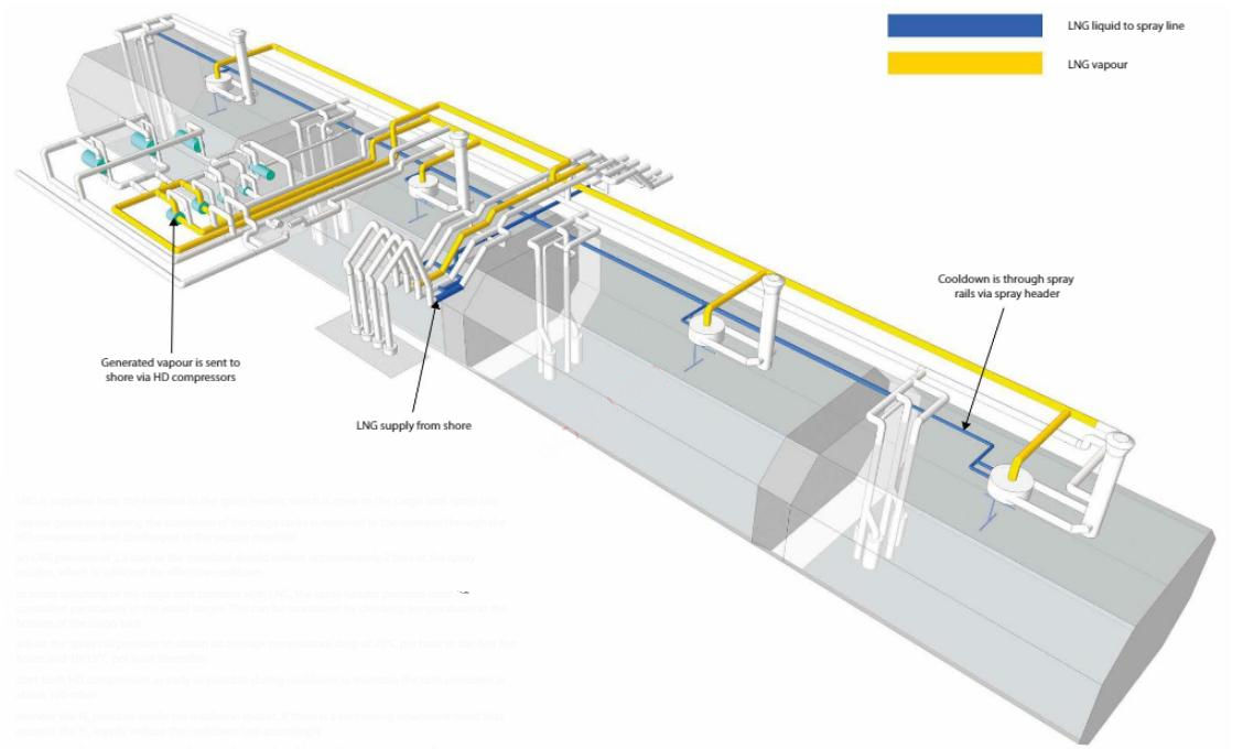
Operational description – cargo tanks cooldown
- LNG is supplied from the terminal to the spray header, which is open to the cargo tank spay rails;
- vapour generated during the cooldown of the cargo tanks is returned to the terminal through the HD compressors and discharged to the vapour manifold;
- an LNG pressure of 3,5 bars at the manifold should deliver approximately 2 bars at the spray nozzles, which is sufficient for effective cooldown;
- to avoid splashing of the cargo tank bottoms with LNG, the spray header pressure must be controlled particularly in the initial stages. This can be monitored by checking temperatures at the bottom of the cargo tank;
- adjust the spray rail pressure to obtain an average temperature drop of 20 °C per hour in the first five hours and 10/15 °C per hour thereafter;
- start both HD compressors as early as possible during cooldown to maintain the tank pressures at about 100 mbar;
- monitor the N2 pressure inside the insulation spaces. If there is a continuing downward trend that exceeds the N2 supply, reduce the cooldown rate accordingly;
- approximately two hours prior to the completion of cooldown, the cargo system is lined up to ensure that the cooldown of all liquid manifolds and the liquid header is completed at the same time as completion of the cargo tank cooldown;
- cooldown of a cargo tank is complete when the mean temperature (except for the top temperature sensor in each tank) indicates minus 130 °C (-130 °C) or lower (depending on terminal requirements). When these temperatures have been reached and the custody transfer measurement system (CTMS) registers the presence of liquid, bulk loading can begin.
Further considerations
Unlike rigid cargo tank designs, vertical thermal gradients in the tank walls are not a significant limitation on the cooldown rate of membrane type LNGCs.
The arrangement of the spray nozzles in each cargo tank is specific to the containment system:
- Moss – 3 spray rings, each of a different capacity;
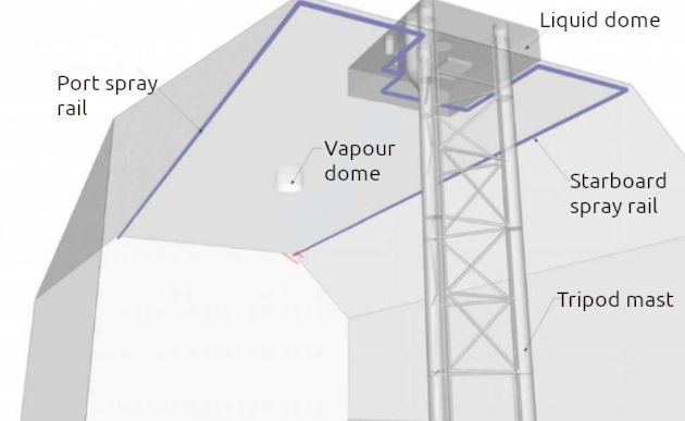
- Mark III – spray rails fitted at the top of the tank port and starboard running from aft (penetration at liquid dome) to forward bulkhead;
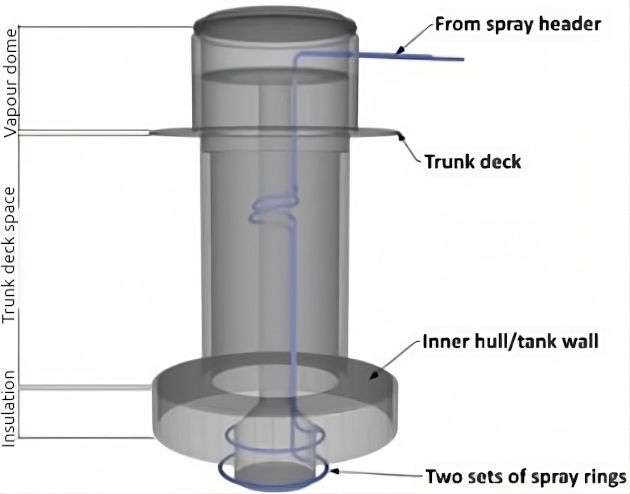
- NO96 – 2 spray rails fitted below the vapour dome of each tank.
Manufacturers cooldown tables provide guidance on the quantity of coolant required for the cooldown operation.
However, it should be noted that cooldown tables will specify energy required in MMBTU rather than m3. When cooldown is carried out alongside terminals that are primarily discharging terminals, the use of “aged” LNG may cause a prolonged cooldown period. A liquid that is delivered to discharging terminals will generally have less CH4, and so less calorific value.
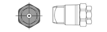
| Nozzle inlet connection NPT | Capacity size | Body orifice diam. nom mm | Cap orifice diam. nom mm | Capacity (litres/minute) | Spray angle | Material | |||||||
| 0,5 bar | 1 bar | 1,5 bar | 2 bar | 3 bar | 6 bar | 0,5 bar | 1,5 bar | 6 bar | |||||
| 3/4 BD – 316LSS25 | 2,5 | 7,1 | 7,5 | 8,1 | 11,4 | 14,0 | 16,1 | 19,7 | 28 | 63″ | 70″ | 74″ | SUS316L |
Do not allow significant temperature difference between cargo tanks in the early stage of cooldown as it may be difficult to equalise them at a later stage.
Once cooldown is completed and ramp-up to bulk loading has commenced, the tank bottom will be at, or near to, liquid cargo temperature. However, it will take some hours to establish fully cooled temperature gradients throughout the insulation. Consequently, boil-off from the cargo will be higher than normal at this stage.

- The international group of liquefied natural gas importers (GIIGNL). LNG custody transfer handbook / 6th Edition: 2020-2021.
- ©Witherby Publishing Group Ltd. LNG Shipping Knowledge / 3rd Edition: 2008-2020.
- CBS Publishers & Distributors Pvt Ltd. Design of LPG and LNG Jetties with Navigation and Risk Analysis / 4th Edition.
- NATURAL GAS PROCESSING & ITS ENERGY TRANSITION ROLE: LNG, CNG, LPG & NGL Paperback – Large Print, November 14, 2023.
- OCIMF, ICS, SIGTTO & CDI. Ship to Ship Transfer Guide for Petroleum, Chemicals and Liquefied Gases / 1st Edition, 2013.
- The Society of International Gas Tanker and Terminal Operators (SIGTTO). Ship/Shore Interface / 1st Edition, 2018.