Gas Steam Turbines are a cornerstone of modern power generation and industrial processes, renowned for their ability to efficiently convert thermal energy into mechanical power. These complex machines utilize steam to rotate a turbine, which then drives a generator or other equipment. Understanding the key components within Gas Steam Turbines is vital for their operation and maintenance. Essential parts include the bladed rotor assembly, carefully engineered casing structures, nozzles directing the steam flow and precisely crafted control valves. Further, shafts and bearings, specifically designed to withstand high-speed rotation and demanding conditions, are crucial for the overall function of the Gas Steam Turbines.
- Gas Steam Turbines
- Overview
- Flexible Couplings
- Quill Shafts
- Journal Bearings
- Bearing Wear
- Reduction Gears
- Overview of A 36 000 SHP Kawasaki Cross-Compound Marine Turbine
- Steam Conditioning
- Steam Dumping
- Steam Dumping Valves
- Steam Cooler
- Steam Sparger
- Steam Conditioning System
- Alternative Propulsion – Diesels
- Overview
- Electric Propulsion Based on Wärtsilä Dual-Fuel Gas Engines
- The LNGC Two-Stroke Solution MAN/B&W ME-GI Dual-Fuel Engines
- Elements of the ME Engine
- Summary
A critical aspect of maintaining the performance and lifespan of Gas Steam Turbines is managing bearing wear. The bearings, whether hydrodynamic or rolling element types, are responsible for supporting the rotating shafts. Over time, wear can occur due to factors such as high operating temperatures, vibrations, lubricant degradation, and contamination. Therefore, regular monitoring and analysis of the bearings are essential. Techniques such as vibration analysis and oil condition monitoring are crucial for detecting early signs of wear. This allows timely intervention to prevent catastrophic failures, ensuring the continued reliable operation of these crucial Gas Steam Turbines. The effective management of bearing wear contributes significantly to the extended operational lifespan of the Gas Steam Turbines and optimizes overall energy production. Ultimately, efficient operation of Gas Steam Turbines hinges on meticulous component maintenance.
Gas Steam Turbines
Overview
Today’s LNGC’s typically:
- have a cargo capacity of 125 000 m3 to 150 000 m3;
- have steam turbine propulsion;
- have a horsepower range of 36 000 to 40 000 shp;
- steam is supplied from two boilers of the modified d-type, which have a generation capacity of 60-70 mt/hour each.
The main engines are cross-compound turbines units featuring high-pressure and low-pressure turbines spinning at approximately 6 000 rpm (hp rotor) and 4 000 (lp rotor) respectively.
Torque is transmitted to the main shaft via a set of double reduction, double input, articulated, nested reduction gears.
Propulsion turbines are configured in a high-pressure and low-pressure configuration for the following reasons:
- Facilitates shorter length rotors, which make manufacturing and installation easier.
- Gear-loading forces are reduced because input is divided between two rotors.
- Two rotors provide redundancy and safety for reduced speed operation should something happen to one unit.
- Torque is transmitted from the rotors to the gears via flexible couplings, which are usually of the gear type or the diaphragm (Bendix) type.
- The gear type has a tendency to trap minor impurities from the lube oil and becomes less flexible over time. This is the reason that they are dismantled and inspected on a periodic basis.
The Bendix type requires no dismantling and needs only to be visually inspected for cracks in its stress-sensitive coating.
Flexible Couplings
Gear type flexible couplings similar to those illustrated in Figure 1 offer a high degree of functionality and reliability. However, there are some basic requirements that must be followed. These are:
- Dismantling and cleaning at regular intervals.
- Prior to dismantling, assure that all parts are properly marked with respect to their location and orientation, and Careful inspection of wearing surfaces, such as gear teeth, to assure there is no sign of misalignment or premature wear.
- Reassembly of cleaned and serviced parts in the same manner as found.
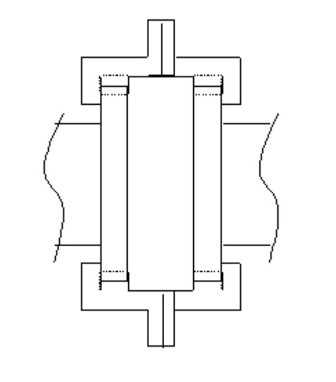
Hybrid variations of this coupling include “General Electric’s” “flexible thrust bearing“, which combines the above coupling with an integral Kingsbury type thrust bearing.
Also to be remembered, parts usually come as a balanced set. For example, if an existing bolt becomes damaged or lost, it is safest to replace the whole set versus one individual piece.
Figure 2 depicts a good or satisfactory wear pattern on gear tooth of flexible coupling.
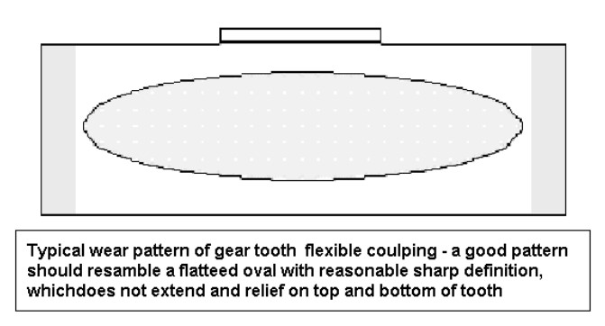
Faults such as misalignment, imbalance, or improper assembly will produce an oddly shaped wear pattern that should prompt investigation of problem(s).
Figure 3 depicts a variation of the preceding gear coupling. Here, a spool piece with a set of male splines at each end meshes with coupling hubs contains the female splines. This configuration is typically used between two “immoveable” pieces of equipment, such as a turbine and a reduction gear.
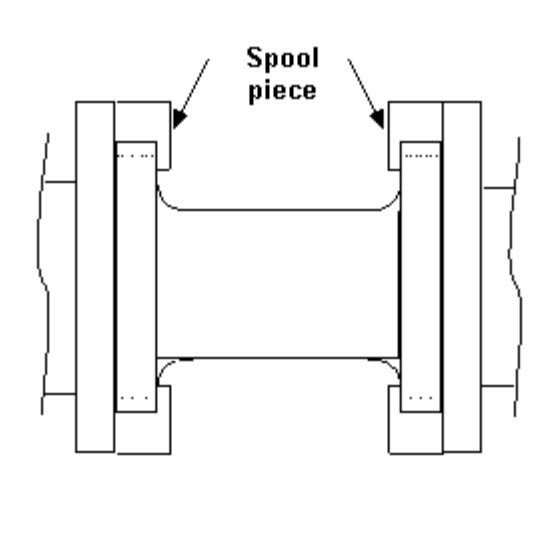
With this configuration, it is possible to completely dismantle the coupling for cleaning and inspection.
When reassembling, special care should be taken to assure that all parts go back in proper order and aligned with manufacturer’s witness marks.
Figure 4 depicts a Bendix or diaphragm coupling. It has also been called a “torque-tube” coupling. Essentially it consists of a tube of high tensile steel connected/welded to two flexible blank flanges. The coupling has no gear teeth and requires no disassembly for cleaning. Its visible surfaces are coated with stress-sensitive enamel that will crack if alignment limits are exceeded.
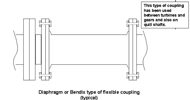
Inspection is accomplished by removal of exterior covers in way of coupling and carefully examining the enamel for cracks, chips, etc.
Bendix couplings can be used in place of traditional gear couplings and they can also be installed on quill shafts.
Some of the advantages of diaphragm couplings are:
- No lubrication required.
- Suitable for high temperature operation.
- Produce low moments and forces.
- Produce predictable moments and forces.
- Easily balanced.
- Produce low vibratory inputs into equipment.
- Higher torque capability without an increase in coupling size.
- Accommodation of greater axial motions.
- Accommodation of greater misalignments.
- Adaptable to all types of connections: splines, taper shafts, etc.
- Operate for years without maintenance or problems.
The Table summarizes a complete comparison between gears and diaphragm couplings.
| Table. Comparison between Gear and Diaphragms Couplings | |||||||
|---|---|---|---|---|---|---|---|
| COUPLING TYPE | O.D. (IN) | WEIGHT (LBS) | CONTINUOUS TORQUE CONDITION (IC-LBS) | CONTINUOUS AXIAL TRAVEL (IN) | AXIAL FORCE AT CONTINUOUS CONDITION (LBS) | CONTINUOUS ANGULAR MISALIGNMENT (DEGREES) | BENDING MOMENT AS CONTINUOUS CONDITION (IC-LBS) |
| GEAR ACCESSORY COUPLING (μ = .075) | 12,75 | 190 | 18 000 | (*) | 440 | ± 25 | 1 900 |
| GEAR ACCESSORY COUPLING (μ = .25) | 12,75 | 190 | 18 000 | (*) | 1,450 | ± 25 | 1 800 |
| DIAPHRAGM ACCESSORY COUPLING | 14,75 | 250 | 18 000 | ±500 | 1,50 | ± 25 | 400 |
| GEAR LOAD COUPLING (μ = .075) | 16,00 | 480 | 534 000 | (*) | 6,870 | ± 25 | 56 300 |
| GEAR LOAD COUPLING (μ = .25) | 16,00 | 480 | 534 000 | (*) | 22,880 | ± 25 | 140 800 |
| DIAPHRAGM LOAD COUPLING | 16,94 | 480 | 534 000 | ±300 | 4,050 | ± 25 | 5 600 |
| (*) GEAR TYPE COUPLING CAN BE DESIGNED FOR UNLIMITED AXIAL CAPACITY | |||||||
The purpose of flexible couplings is to compensate for minor misalignment between two fixed pieces of machinery such as turbine rotors and high-speed pinions, pumps and motors, etc.
There are other types of flexible couplings such as grid-type as manufactured by “Falk“, which utilize a sinuous spring that meshes with teeth in the outer periphery of the coupling hubs; pin-type, which utilize axially oriented bolts in the coupling hubs which engage holes in the opposite hub, as well as others. However, for large horsepower machinery, the gear and diaphragm type couplings are the most prevalent.
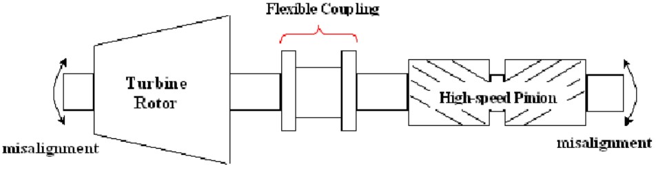
With regard to marine turbines, flexible couplings are installed between the high pressure (hp) turbine rotor and the hp high-speed pinion gear in the reduction gearbox. Also, there is a flexible coupling installed between the low pressure (lp) turbine rotor and the lp high-speed pinion gear.
Figure 5 depicts a general configuration of turbine rotor, flexible coupling and high-speed pinion gear.
Quill Shafts
The most practical way to explain a quill shaft is to describe it as a flexible coupling with an elongated spool piece. Like their counterparts, flexible couplings, quill shafts are used to compensate for minor misalignment between fixed rotating components. However, unlike flexible couplings, quill shafts are usually an internal component and not readily accessible and therefore are almost never dismantled or removed for inspection.
In the case of main propulsion turbine reduction gears, the quill shaft is “buried” within the gear train between the 1st reduction gear and the low-speed pinion. The important thing to remember is that the purpose of the quill shaft is to allow the 1st reduction gear to be in the same exact rotating plane as the high-speed pinion gear, and the low-speed pinion gear to be in the same exact rotating plane as the 2nd reduction, or bull gear.
The most common means of engagement for a quill shaft are gear splines as in the gear-type flexible coupling. However, there are instances where Bendix-type diaphragm couplings have been used in lieu of gear teeth. Without a quill shaft, it would be exceedingly difficult (and expensive) to fabricate a large gearbox and have all of the gears perfectly aligned.
There are several variations of quill shafts, but most are similar to the simplified version that is shown in Figure 6.

Another major component of turbines and gears are thrust bearings. For marine propulsion turbines, the most practical thrust bearing is a tilting-pad bearing commonly referred to as a “Kingsbury” thrust bearing. The Kingsbury bearing replaced the earlier “horseshoe” type of thrust bearing.
This type of bearing consists of a shaft with a fixed radial collar, which bears up against pie-shaped pivoting pads arranged around the face of the collar. The pads, also called “shoes“, have a smooth face, which bears up against the collar. On the back, or side opposite the face, there is a rounded surface or “button“, which allows the pad to tilt in such a manner as to facilitate the formation of an oil-wedge.
The surface area of the collar and shoes is calculated to be sufficient to accommodate the maximum allowable axial thrusts (both directions) without failure or touching of metal parts.
Each turbine rotor has its own dedicated thrust bearing, which keeps it in exact, axial running alignment with relation to nozzles and stationary blading. Main line shafting also has a similarly configured thrust bearing, which is sufficiently sized to accommodate the entire thrust of the main engines and resistance of the hull going through the water.
Figure 7 shows assembled Kingsbury type thrust bearing used in Kawasaki LP turbine rotor.
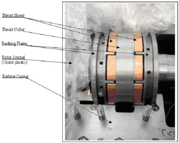
The copper colored pieces are the thrust shoes; the collar is between both sets of shoes.
Figure 8 shows same LP thrust bearing, at left in photo, and provides good view of rotor journal surface and lower half of journal bearing.
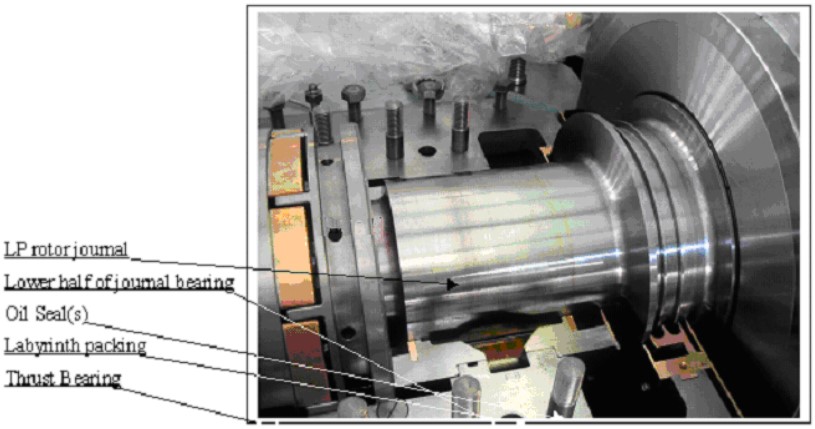
Figure 9 depicts a Kingsbury type thrust bearing in operation.
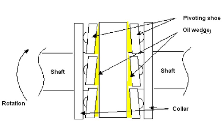
The formation of the oil wedges is based upon principles of boundary film lubrication and is further influenced by the properties of the lube oil viscosity, load factor, etc.), the axial clearances of the bearing, rotational speed of the shaft, and the size and physical condition of the shoes (for instance, leading edges cannot be sharp).
Journal Bearings
In marine propulsion turbines and gears, the rotating parts are supported and kept in alignment by oil fed, white metal journal bearings. The bearing or supporting surface of the rotating part is called the journal. Hence, the bearing, which supports the rotating journal, is called a journal bearing.
Journal bearings are essentially tubes, which fit around the journal of the rotating part. Lubricant is usually introduced into the bearing in a non-contact zone, such as the top or sides of the upper half of the bearing, so that the rotation of the part can assist with distributing the lubricant and subsequent formation of the oil wedge.
As mentioned in thrust bearings above, the formation of the oil wedge is based upon principles of boundary film lubrication and is further influenced by the properties of the lube oil (viscosity, load factor, etc.). With journal bearings, however, it is the radial clearances the bearing, as well as rotational speed of the shaft, and the length and physical condition of the bearing which contribute to the successful operation of the bearing.
One variation of the conventional journal bearing is the self-aligning, tilt-pad bearing (not shown). Like a thrust bearing, it has shoes that can pivot. In this manner, it can compensate for minor axial misalignment.
Figure 10 illustrates comparison of rotating part at rest, A, and rotating counter-clockwise, B.
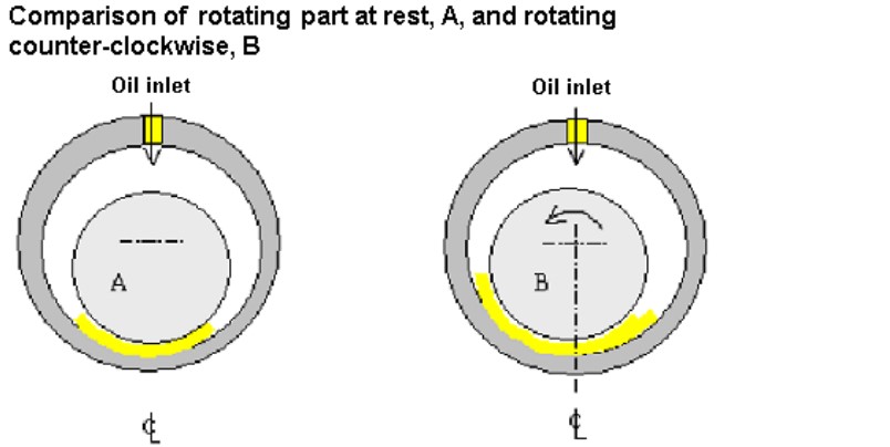
The important aspects to notice are:
- at rest, A, the shaft is centered in the bearing;
- in A, a uniform boundary layer of lubricant is present;
- in B, as the shaft rotates, it will climb in the bearing to a position that is eccentric with relation to the bearing centerline;
- in B, a dynamic oil wedge will form, which will support the shaft throughout is operational range.
Bearing Wear
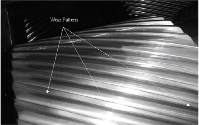
Figure 11 depicts wear patterns on lower bearing shells that one would encounter as part of survey.
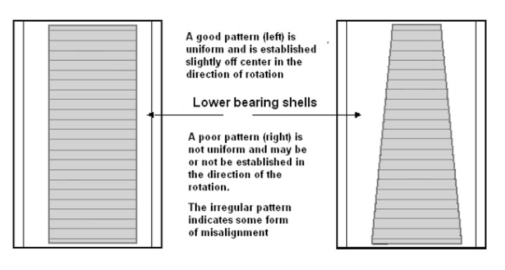
A good pattern is usually established in either the 7:00 or 5:00 position, in the direction of rotation. As indicated, a good wear pattern (right) is fairly uniform in shape and looks like a rectangle.
An irregular pattern can resemble a trapezoidal shape and is usually indicative of misalignment. One variation of a bad pattern is a rectangular pattern that is beyond the 7:00 or 5:00 position, in the direction of rotation. This can indicate poor radial alignment and should be investigated further by inspecting adjacent bearings, or closely examining helixes (if working with gears).
Bearings should also be inspected for minor wiping or wire edging, delamination from base, loss of dowel pins, and improper seating of upper and lower shells. Clearances should be checked with:
- lead wire;
- plasti-gauge;
- micrometers;
- or feeler gauges;
- and recorded.
Reduction Gears
With regard to LNGC Project Factors and Cargo Containment SystemLNGC’s, today’s gear sets are relatively simple and straightforward. Starting with the HP and LP turbine rotors, each drives a single high-speed pinion gear, which, in turn, meshes with and drives a 1st reduction gear. Then, by means of a quill shaft, the 1st reduction gear drives a low-speed pinion gear, which, in turn, meshes with and drives a 2nd reduction or bull gear.
Figure 12 illustrates a turbine and gear train.
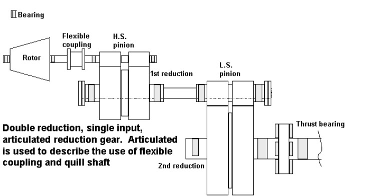
For simplification, only one turbine rotor is shown. The shaded areas indicate journal and thrust bearings. The dotted lines between the 1st reduction and the LS Pinion indicate the quill shaft.
Figure 13 provides an illustration of a double-input, double reduction, double articulated (two quill shafts for first red-gear and second red-gear) locked train reduction gear (two quill shafts for first red- gear and second red-gear).
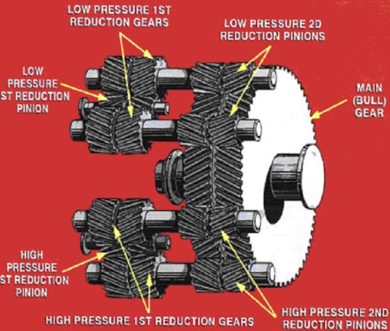
The term “locked train” refers to the fact that the 1st reduction gears and low-speed pinions are pre- torqued and set or “locked” in place. This procedure is done in order to evenly distribute the work load(s) among all of the gears.
This configuration is similar to the Mitsubishi reduction gears used at Samsung Heavy Industries.
With regard to inspection of reduction gears, the following patterns illustrated in Figures 14, 15 & 16, will provide the best example of what a surveyor may encounter.
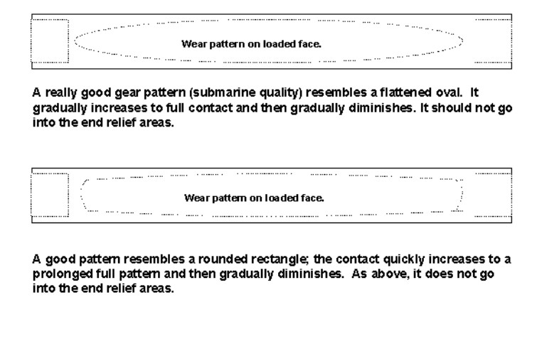
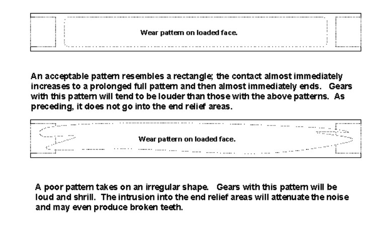
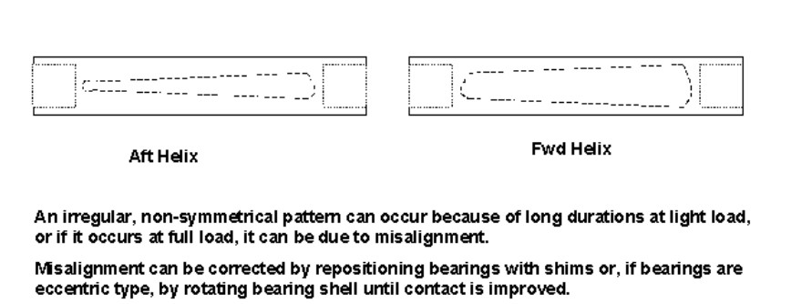
Figure 17 shows HP low-speed pinion gear post dock trials. The wear pattern on the loaded face (indicated) is acceptable for light load condition. Many owners prefer to have several of the gear teeth marked with a commercial dye, such as Dykem, which facilitates viewing the wear pattern.
Powdered graphite can be applied to a clean dry gear face and “lifted” with clear cellophane tape. These tapes can then be applied to white paper, where the wear pattern will be clearly indicated.
Overview of A 36 000 SHP Kawasaki Cross-Compound Marine Turbine
Typical main engines for LNGC’s are Kawasaki Type UA, cross-compound turbines featuring a high-pressure and low-pressure turbine spinning at 4 962 rpm (hp) and 3 275 (lp) respectively.
Torque is transmitted to the main shaft via a set of double reduction, articulated, double input, nested reduction gears (Figure 18).
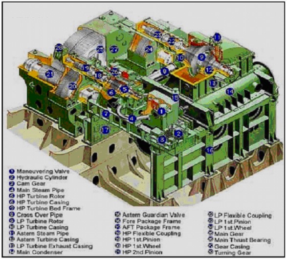
The Kawasaki Type UA is a simple, rugged, and reliable propulsion unit. The main condenser (not clearly shown) is attached to the underside of the LP turbine casing. This will be shown in subsequent photos.
Figure 19 shows a Kawasaki LP turbine rotor in lathe for final machining of circumferential slots into which the balding will be fitted.
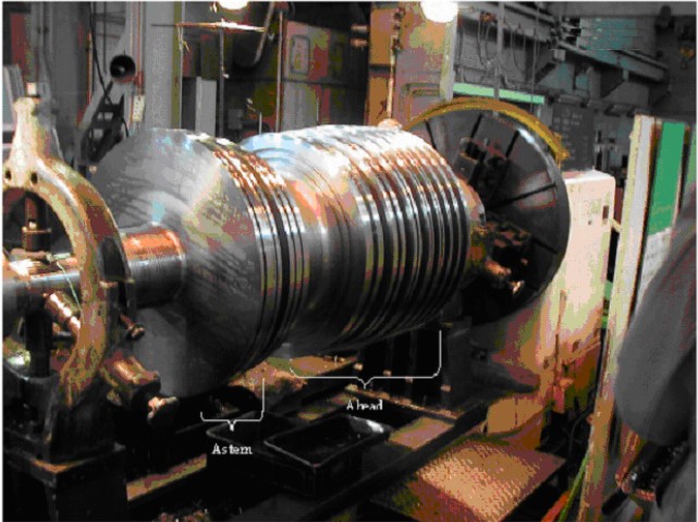
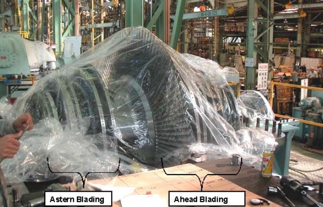
The astern wheel/element is closest (left in photo) and consists of 4 rows of rotating, or moving blading. The ahead wheels are to the right in the photo and consist of eight wheels or elements.
Not shown in the photo are the insertion slots in each wheel, into which the blading is inserted and then slid radially around the wheel to its final position. The slot is usually close with either a special blade or sometimes a blank. If a blank is used, a corresponding or matching blank is inserted first and then slid around to a position 180° opposite the insertion slot. This makes subsequent dynamic balancing much easier.
Once all blading, shrouding is installed, the assembly will have NDE carried out and then sent off for dynamic balancing. Balancing is usually done in an enclosed bunker and under vacuum. The vacuum prevents the rotor from developing excessive axial thrust on the test stand and also from overheating due to air friction.
NDE is usually done prior to spin testing to assure that nothing will fly apart during the spin test and afterwards, as well, to assure that no subsequent flaws have developed.
Figure 20 shows assembled LP rotor sitting in lower half of LP casing.
In this phase of construction, the axial clearances will be checked, and appropriate shims machined and installed in the rotor thrust bearings. Radial clearances will also be taken and the journal bearings adjusted accordingly. Kawasaki uses traditional white metal sleeve bearings. Other companies, such as Demag DeLaval use tilt-pad journal bearings.
The lower halves of the interstage diaphragms, or stationary blading, have been added just prior to installing the rotor. There are several variations of the methods of attachment of the diaphragms, but essentially they are installed as per Figure 21.
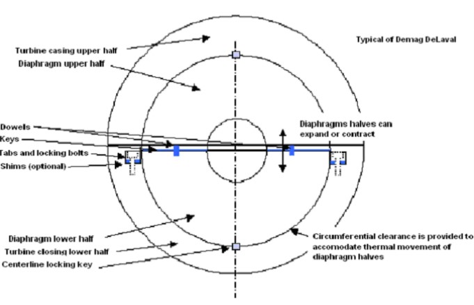
This allows the diaphragms to expand and contract, upwards and downwards, neutrally around the turbine rotor. The purpose of the blades in the diaphragms is to change the direction of steam flow so that it meets the subsequent moving blades at the correct angle. No pressure drop occurs through the diaphragms.
The height of the diaphragms is set by adjusting the lower halves; the upper halves then rest upon the lower halves and are held in place with dowel pins and keys. Sideways or lateral adjustment of the diaphragms should not be necessary unless the manufacturer has made an error in casing fabrication.
In the shipyard, a surveyor would not normally be concerned with this phase of turbine work; however, it is common for factory acceptance test (FAT) or inspection.
Figure 22 shows close-up view of LP rotor in lower half of LP casing.
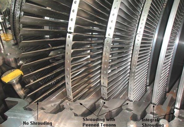
Of interest is the method of shrouding on the rows or blading. To the right is integral shrouding in which the blade and shroud are one piece. Often, this type of shrouding is further reinforced with banding wire, which is rolled into integral channels in the top of the shrouding.
The middle rows of blading have traditional or discrete shrouding, which is essentially strips of metal with holes drilled to accommodate the tenons at the end of the blading. The shrouding is rolled to a curvature that matches the curvature of the end of the blades. The tenons are then peened to a “button” shape in order to secure the shrouding in place. Of note, the holes for the tenons must be scribed at the base of the tenons and not the tips – the latter practice will cause cracked tenons and loss of shrouding in service.
The purpose of shrouding is to eliminate resonance or vibration in the blading and to minimize end loss of steam around the balding. Spill stripping, both integral and discrete, can also be seen in way of the shrouding. This further reduces end loss of steam around the blading.
The last row of blading on the left has no shrouding. This is also the last row of ahead blading and as such, the absence of shrouding does not significantly effect performance or efficiency.
Figure 23 shows closer view of LP blading and diaphragms.
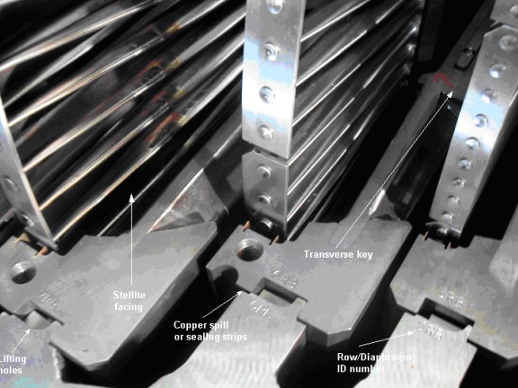
Note the numbers on the diaphragms and the corresponding numbers on the casing. This is done to assure that the right diaphragm goes back in the right place.
On this particular unit, the diaphragms are all differently sized, so each one can only go into its designated location. However, on larger units, the diaphragms are the same or similarly sized – the blading length will vary – therefore, the numbering becomes crucial.
A portion of one of the transverse keys can be seen on row 6. These keys help hold the diaphragm in place axially and also act as a seal to minimize steam flow through the diaphragm mating surfaces.
The copper spill strips or sealing strips placed in the diaphragms prevent end loss around the diaphragms.
In row 7, the stellite facing on the leading edge of the blading can be clearly seen. This is to protect against erosion from moisture impingement that occurs during reduced speed or improper superheat.
Figure 24 shows close-up view of rows 2, 3, and 4 of Kawasaki LP rotor ahead blading.
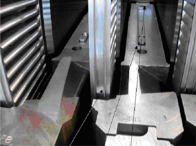
The 3rd stage diaphragm and its transverse key can be clearly seen. At the extreme end, the interstage labyrinth shaft seal can be seen. This keeps steam from bypassing the diaphragm in way of the rotor. During inspection, the keys must be inspected for nicks, burrs, etc., which might prevent the diaphragm halves from fitting together smoothly.
During assembly of the casing, the upper diaphragm halves hang down beyond the upper casing surface. This is so that the mating with the lower diaphragm halves can be clearly seen.
Note that the shrouding is different than that of the later stages. This type of shrouding is integral with the blade and is thus called integral shrouding. Note that the spill or sealing stripping is also integral. This speeds up fabrication of the rotor.
Integral shrouding is common on smaller blading where the weight of the shrouding is small in comparison to the blade. With larger blades, the discrete shrouding and tenon configuration provides a satisfactory weight solution.
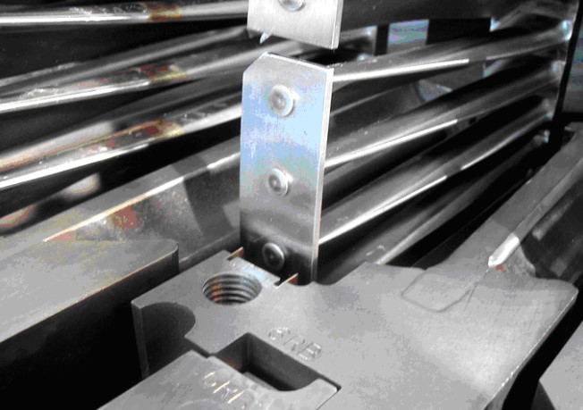
Figure 25 shows close-up view of Number 6 row of ahead blading on Kawasaki LP rotor. Discrete shrouding and peened tenons can be readily seen. The notch cut out of the shrouding allows the assembler to correctly orient the shroud once it has been drilled to accommodate the tenons.
The copper spill stripping is usually caulked into the circumferential grooves with iron calking strips. Figure 26 shows Kawasaki main condenser without water boxes attached.
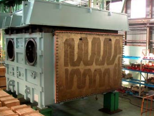
The lanes of tubing are setup to most efficiently direct and distribute the LP turbine exhaust steam flow over the greatest surface area of tubes to minimize overheating. The large pieces of piping on the left side of the condenser are the turbo-generator exhaust inlets.
The tubing arrangement is also set up to efficiently handle steam dumping.
The large flanged area at the top of the condenser is for direct mounting of the LP turbine. The HP turbine will be attached to the beams but not to the condenser. The HP turbine will be attached to the beams but not to the condenser.
Figure 27 shows completed bull gear ready for installation.
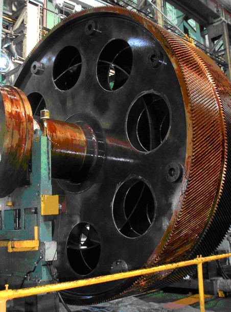
Note the internal reinforcing ring. Today, large gears are not cast. Instead, they are built-up of various components.
In this manner, the gears are lighter in weight and equally as strong as solid gears. This fabrication method also allows the manufacturer to mix and match alloyed steels to ideally suit its location and function within the gear – something that one-piece casting does not allow.
Figure 28 shows a main engine reduction gear about to be installed in a DSME hull.
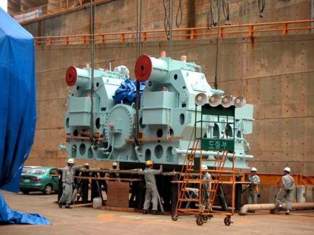
The bull gear extends down below the casing and is protected with a separate cover.
Figure 29 shows Kawasaki assembled main condenser and attached turbines (lp visible) about to be installed.
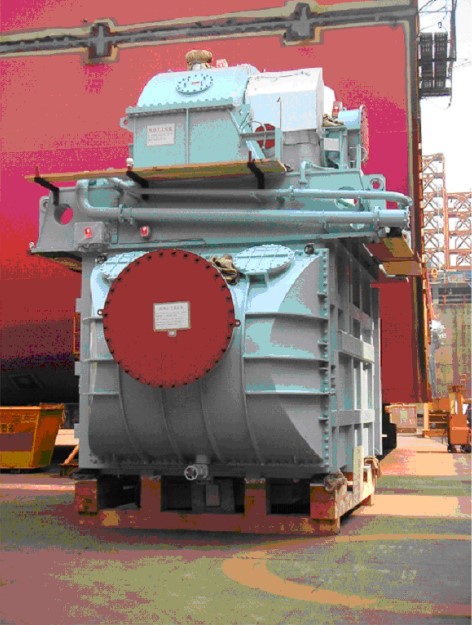
Today’s condensers are one-pass, i. e. the cooling water goes in one end and comes out the opposite end without a change in direction. Older vessels (general cargo- not LNGC’s) often had double-pass or return-flow condensers, but these are rarely seen today. The hotwell is barely visible through the timbers of the shipping cradle.
The reduction gears are installed first and aligned with the shafting. Then condenser and turbines are installed on vessel and aligned with the reduction gears. This sequence involves minimal rework and realignment.
Figure 30 shows reduction gears (left) and condenser and turbines (right) as they are set on dock floor.
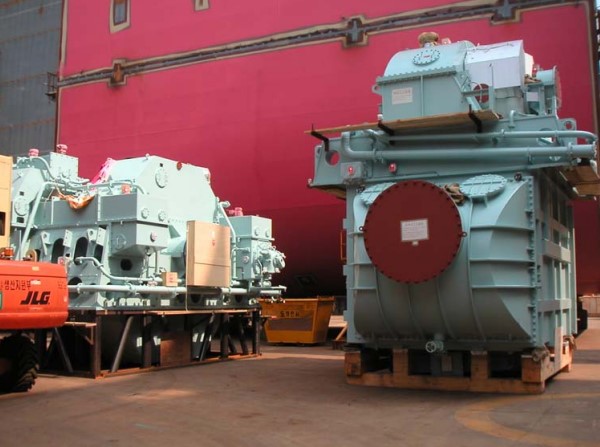
It is prudent to inspect units for shipping/handling damage when they arrive in yard, when they are set in dock, and also when they are set in place on the ship.
Steam Conditioning
There are basically four ways to deal with excess pressure, or boil-off, in General Overview of LNG Cargo Tanks (Typical Operations)LNG cargo tanks:
- send it ashore to the terminal, via the return vapor compressor and vapor line;
- vent it to atmosphere via vent mast;
- reliquify it via on-board reliquification plant;
- send it back to machinery space as fuel for boilers.
It is this last option, which leads to the need for a steam conditioning or “steam dumping” system.
Steam Dumping
“Steam conditioning“, or steam dumping, refers to the practice of dumping of live steam, from the boilers, directly to the main condenser – without that steam having done any work or other function.
Since the steam is at high pressure and high temperature, it must be reduced and cooled (hence the term conditioned) so that it does not over pressurize and/or overheat the main condenser.
Companies such as “Fisher” and “Yarway” have developed specially-designed valves which accomplish the conditioning in a safe and efficient manner.
Steam Dumping Valves
Steam conditioning valves are essentially reducing valves combined with an attemperator. The first reduction in pressure occurs across the valve in much the same manner as a reducing or regulation valve. The second reduction in pressure occurs with the attemperator, which also simultaneously reduces the temperature of the steam.
The attemperator uses significant amounts of water, either from the main feed system or the atmospheric drain system. Figure 31 shows a typical angle steam conditioning valve with spray-water injected in the direction of steam flow immediately downstream of the seat where velocity and turbulence are high.
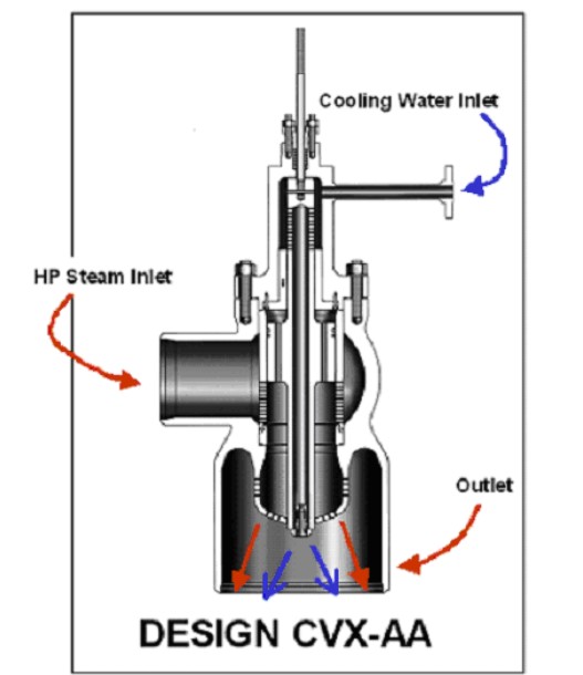
High velocity and turbulence helps mix the water quickly and evenly throughout the steam flow. Design allows for intrinsic feed forward control due to the direct proportioning of water addition to steam flow.
Figure 32 shows an angle steam conditioning valve with multiple spray nozzles injecting water radially from an externally mounted manifold.
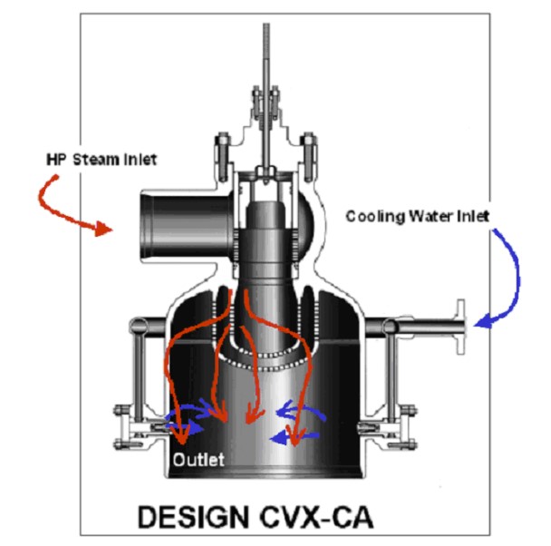
Water is injected downstream of the seat where turbulence is high. High turbulence helps ensure quick and even mixing throughout the flow. Multiple nozzles allow for large water-flow addition.
Steam Cooler
The steam cooler (see Figure 33) is similar to the outlet section of the CVX-C valve and is normally used where separation of the pressure reduction (CVX-P) and desuperheating functions is required.
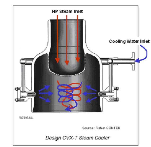
The steam cooler is equipped with a water supply manifold or multiple manifolds, which provides cooling water to a number of spray nozzles in the pipe wall of the outlet section. The fine spray provides very efficient mixing and almost immediate vaporization.
The steam cooler section can accommodate a silencer, which decreases steam pressure energy in a controlled velocity expansion.
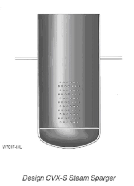
Steam Sparger
The steam sparger is a diffuser used where further pressure reduction is needed downstream of a valve.
It also can provide a constant back-pressure to the valve. The sparger is a fixed, multiple orifice device that inserts into the piping (see Figure 34).
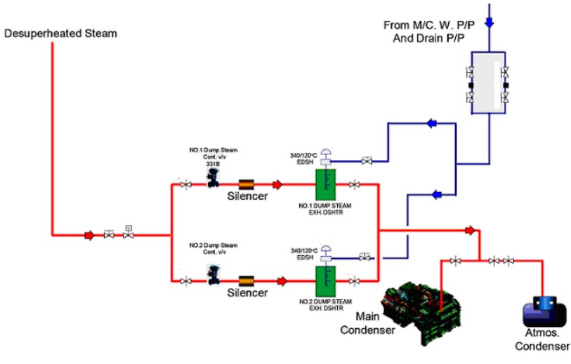
Steam Conditioning System
A steam dumping system requires its own control loop, which is separate and apart from the main combustion control and burner management system of an LNGC.
As boil-off is burned in the boilers, steam pressure rises. To compensate for this rise, the boiler(s)’ combustion control decreases the oil or base flame to minimum pressure and decreases the number of burners to minimum.
When the pressure rises beyond the boilers’ set-point, and reaches the steam dumping system’s set point, the attemperating water supply opens just before the steam dump valve opens thus preventing superheated steam from entering the condenser.
When steam pressure drops below dumping set point, the steam condition valve closes first; followed almost instantaneously by the attemperating water supply (see Figure 35).
Alternative Propulsion – Diesels
Overview
From the very beginning, LNGC’s have been propelled by steam turbines even though the rest of the world’s fleets have now shifted to diesel propulsion. The abandonment of the turbine, by all other commercial vessels, has brought about by advances in diesel technology – most notably fuel efficiency and increases in engine size (up to and exceeding 96 000 bhp).
Steam plants are still used on LNGC’s for the following reasons:
- LNG boil-off can be readily and beneficially consumed in the boilers.
- The ability to “steam dump” excess boiler pressure brought about by burning boil-off during light-load, or in-port conditions.
- Steam plants are reliable.
- Redundancy – two turbines and two boilers.
There are two broad categories of Marine Propulsion Diesels:
- Large, slow speed, direct drive – up top 96K bhp.
- Smaller, medium speed (up to and exceeding 20 000 bhp):
- Gear drive.
- Electric drive.
Currently, the ability to burn methane (even as a dual fuel) in a diesel, is newly-developed, existing technology that is being adapted and considered for the LNG trades. However, there are some unique requirements of the LNG trade, which must be addressed before diesels take over this last bastion of the steam turbine. These requirements are:
- Many LNG terminals require that an LNGC’s main engines be ready to go at a moment’s notice. With regard to a large, slow-speed diesel, this means that it may not be allowed to change a piston, rings, liner, etc. or perform other maintenance, which can only be done in port. With regard to a slow-speed diesel, when will it do its maintenance if it cannot do it in port? Doing a piston-pull at sea is not advisable.
- With multiple engines, it may be possible to do maintenance in port.
- In port, there is often additional boil-off that must be burned. Without a steam dumping system, or reliquification system, how is a diesel plant to handle this without venting?
With regard to medium speed diesels, especially with electric drive, the ability to burn the boil-off and power the vessel’s electric load is definitely feasible. This capability, coupled with a reliquification plant may well be sufficient to handle all of the boil-off without having to resort to a steam dumping system. Another means of handling the boil-off is to burn it in a gas burning equipment. This is no more wasteful than steam dumping, and is thus very feasible.
Electric Propulsion Based on Wärtsilä Dual-Fuel Gas Engines
Wärtsilä considers most the feasible approach for LNG carriers to be based on electric propulsion where the prime movers in the power plant are four-stroke low-pressure dual-fuel gas engines. The main arguments in the comparison are high thermal efficiency and safety as well as flexible and efficient use of the installed machinery.
The selection of either single-screw or twin-screw ship will be based on the operating profile and redundancy requirements specific for each project.
The number of engines and the power output of each unit are determined by the shaft power needed and also by the degree of redundancy requested.
Generally speaking on a typical 135 000 m3 ship with the need for approximately 30 MW total engine output the power plant would consist of four gas-engine generating sets of the Wärtsilä 50DF type. The MCR output of these engines is 950 kW/cylinder and the thermal efficiency as high as 46,5 %!
The recommended plant would consist of a combination of eight or nine cylinder units. For example a plant with four 9V46GD would provide nearly full redundancy even if one of the engines were out of service. On the other hand it would also provide welcome flexibility for the different operating modes such as maneuvering, waiting for port access, loading and unloading.
Recent studies suggest that the most beneficial solution to top up the need for additional energy is to use forced boil-off instead of fuel oil. This solution in combination with dual-fuel engine electric propulsion is economically superior both in installation cost and operation.
As the dual-fuel engine is operated on low-pressure gas, between four and five bar at the engine inlets, the fuel gas compressor package is essentially identical to the one already in use in the current LNGC fleet equipped with steam boiler and turbine propulsion. The main difference is that the total efficiency of an electric propulsion plant based on dual-fuel engines is well above 40 % compared to the reported 30 % or less of the steam plant.
Moreover, flexible preventive maintenance at sea and during port calls is possible, which has not been the case with the steam plant or with large single two-stroke alternatives. Diesel-electric propulsion technology is also available today and has been proven in various marine applications.
Wärtsilä dual-fuel engines have accumulated a considerable number of operating hours in land-based installations and are mature for marine installations. In other words, everything is ready for taking the next step towards modern, efficient Managing Laden Voyages – BOG Management and Propulsion Systems for LNG CarriersLNG carrier propulsion.” – Mika Laurilehto, General Manager, Application Development, Marine & Licensing Wärtsilä Corporation“.
Figure 36 shows Wärtsilä’s patented dual-fuel inlet manifold.
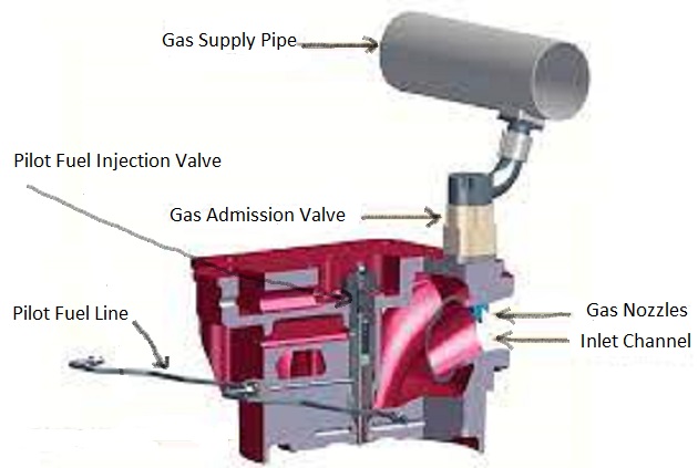
One significant aspect is that is uses existing gas compressors operating at current pressures to achieve this dual fuel capability.
Figure 37 shows Wärtsilä’s proposed configuration for diesel electric drive.
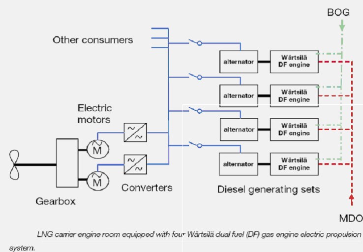
The main advantages of using a number of medium speed units versus one large low-speed unit are:
- A number of smaller engines can be arranged in a manner which best conforms to a ship’s hull; thus making overall engine room smaller, and cargo capacity greater.
- A number of smaller engines provides redundancy. One engine can be secured for maintenance while the rest provide full power. Two drive motors provide the same redundancy as an hp & lp turbine.
- Diesel electric package provides better equipment utilization. The same generators, which drive the propulsion motor at sea, are used to drive all of the cargo equipment in port.
The electric drive does not present the same overload conditions that direct drive units experience – i. e., no time in the “B“- range with the resultant high combustion pressures, etc.
Figure 38 depicts the versatility of the medium-speed, diesel electric drive.
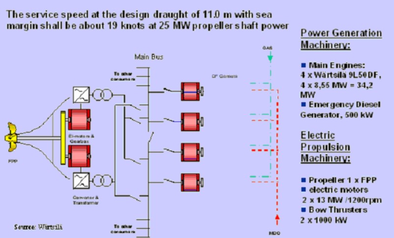
Essentially, one or more diesel generators would be in continuous use with the remainder being either standing-by or secured for maintenance. Currently, the Wärtsilä medium-speed configuration is the only diesel LNGC under actual construction.
The LNGC Two-Stroke Solution MAN/B&W ME-GI Dual-Fuel Engines
This range of engines is designed for the highly specialized LNG carrier market. The design builds on experience gained from the earlier MC-GI engines combined with the developments in the latest electronically controlled ME engines.
After careful consideration of the various alternatives for LNG carrier propulsion, the conclusion from MAN B&W is that a two-stroke engine solution is the best system for powering LNG carriers.
The combination of low installation and running costs for this highly specialized type of vessel makes the adoption of the dual fuel ME-GI engine from MAN B&W very attractive for any ship owner and operator who needs to keep their costs to a minimum. An additional reliquification plant allows sale of more gas when the gas price is higher than the fuel oil price.
Out of all the options for the prime mover, the low speed two-stroke diesel engine gives the best thermal efficiency for any conventional propulsion system. This is especially the case for LNG carriers, where the power requirement is around 30 to 40 MW. Thermal efficiencies of around 50 % for diesel engines may be obtained.
Responding to a market demand for more efficient engines, while retaining the option to burn the boil off gas, “MAN B&W” is now reintroducing its high pressure gas injection low-speed diesels – this time, with electronically controlled injection.
“… Among the many proposals and ideas for LNG carrier propulsion the ME-GI, also installed with reliquification technology, where preferred, provides the best solution for the future needs of the LNG transportation market.” – Vice President of Two-Stroke Sales, MAN/B&W, Mr. Ole Grøne.
Designated by “MAN B&W” as the ME-GI, this gas burning option is also being offered in parallel to the heavy fuel-burning solution with gas reliquification. The combination of the ME-GI engine, installed with a reliquification plant, allows the owners and operators the choice to either use the boil off gas in the engine or to reliquify the gas and use HFO instead – the choice being dependent on their relative prices and availability, as well as environmental considerations.
Figure 39 compares the thermal efficiencies of the various means of propulsion.
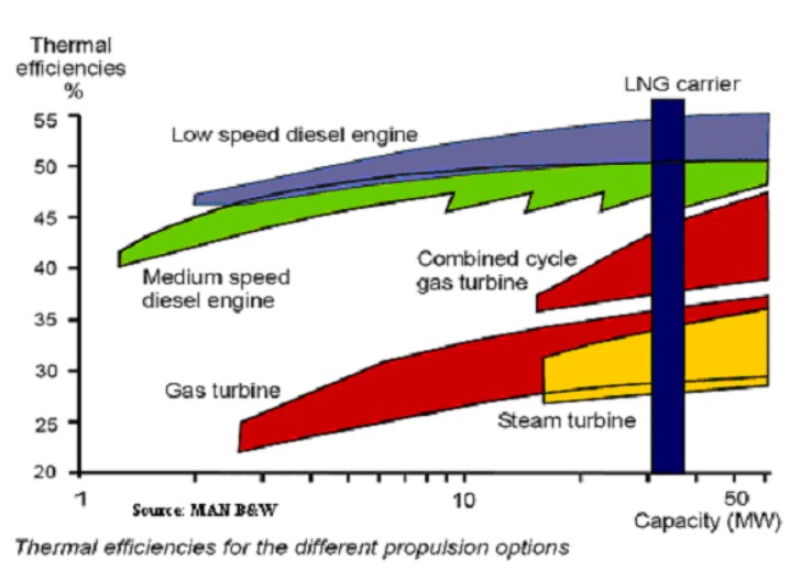
Even a cursory glance indicates that the steam turbine, despite its proven reliability, is at least 10 % lower in overall efficiency, and in the case of the slow speed diesel, almost 20 % lower. Given today’s high price of fuel and the expected 40-year vessel life, one can readily understand why there is an impetus to replace the turbine.
There has been discussion of using a slow-speed, twin-screw configuration on a 200 000+ m3 LNGC. With such a configuration, the previously mentioned maintenance considerations should be easier to manage.
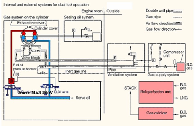
Figure 40 illustrates “MAN B&W’s” approach to dual fuel operation. Also, please notice the on-board reliquification plant. This is essential for handling boil-off during periods of light engine load due to absence of steam dumping system.
Elements of the ME Engine
The mechanical difference between an MC-C engine and its electronically controlled counterpart, the ME-C engine, constitutes a number of mechanical parts that are made redundant and replaced by hydraulic and mechatronic parts with enhanced functions.
The following parts are omitted:
- Chain drive, Chain wheel frame.
- Chain box on frame box.
- Camshaft with cams.
- Roller guides for fuel pumps and exhaust valves.
- Fuel injection pumps.
- Exhaust valve actuators.
- Starting air distributor.
- Governor.
- Regulating shaft.
- Mechanical cylinder lubricator.
- Local control stand.
The above-mentioned parts are replaced by:
- Hydraulic Power Supply (HPS).
- Hydraulic Cylinder Units (HCU).
- Engine Control System (ECS).
- Crankshaft position sensing system.
- Electronically controlled Alpha LubricatorLocal Operating Panel (LOP).
Figure 41 shows how the necessary power for fuel injection and exhaust valve operation – previously provided via the chain drive – is now provided from a Hydraulic Power Supply (HPS) unit located at the front of the engine at bedplate level.
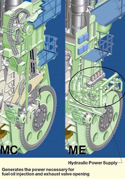
The main components of the Hydraulic Power Supply unit are the following:
- Self cleaning filter with 10-micron filter mesh.
- Redundancy filter with 25-micron filter mesh.
- Start-up pumps:
- Electrically driven pumps with supply pressure of 175 bar.
- Engine driven axial piston pumps supplying high-pressure oil to the Hydraulic Cylinder Unit with oil pressures up to 250 bar.
Summary
Advances in technology coupled with high fuel costs have forced shipyards and owners to reconsider the “traditional” means of propulsion for LNGC. As of this date, only one new build LNGC is diesel electric drive. Given the conservative nature of the marine industry, the world will be watching the performance of this particular vessel; if it is successful, then we may well see a stampede to diesel propulsion.

- The Society of International Gas Tanker and Terminal Operators (SIGTTO). Liquefied Gas Handling Principles on Ships and in Terminals (LGHP4) / 4th Edition: 2021.
- The international group of liquefied natural gas importers (GIIGNL). LNG custody transfer handbook / 6th Edition: 2020-2021.
- American Gas Association, Gas Supply Review, 5 (February 1977).
- ©Witherby Publishing Group Ltd. LNG Shipping Knowledge / 3rd Edition: 2008-2020.
- CBS Publishers & Distributors Pvt Ltd. Design of LPG and LNG Jetties with Navigation and Risk Analysis / 4th Edition.
- NATURAL GAS PROCESSING & ITS ENERGY TRANSITION ROLE: LNG, CNG, LPG & NGL Paperback – Large Print, November 14, 2023.
- American Gas Association, Gas Supply Review, 5 (February 1977).
- The Society of International Gas Tanker and Terminal Operators (SIGTTO). Ship/Shore Interface / 1st Edition, 2018.
- Department of Transportation, US Coast Guard, Liquefied Natural Gas, Views and Practices Policy and Safety, p. IV-3.
- Department of Transportation, US Coast Guard, Liquefied Natural Gas, Views and Practices Policy and Safety, p. IV-4.
- Federal Power commission, Trunkline LNG Company et al., Opinion No. 796-A, Docket No s. CP74-138-140 (Washington, D. C.: Federal Power Commission, June 30, 1977).
- Federal Power Commission, Final Environmental Impact Statement Calcasieu LNG Project Trunkline LNG Company Docket No. CP74-138 et al., (Washington, D. C.: Federal Power Commission, September 1976).
- Federal Power Commission, «FPC Judge Approves Importation of Indonesia LNG».
- OCIMF, ICS, SIGTTO & CDI. Ship to Ship Transfer Guide for Petroleum, Chemicals and Liquefied Gases / 1st Edition, 2013.
- Federal Power Commission, «Table of LNG imports and exports for 1976», News Release, June 3, 1977, and Federal Energy Administration, Monthly Energy Review, March 1977.
- Office of Technology Assessment LNG panel meeting, Washington, D. C., June 23, 1977.
- Socio-Economic Systems, Inc., Environmental Impact Report for the Proposed Oxnard LNG Facilities, Safety, Appendix B (Los Angeles, Ca.: Socio-Economic Systems, 1976).
- «LNG Scorecard», Pipeline and Gas Journal 203 (June 1976): 20.
- Dean Hale, «Cold Winter Spurs LNG Activity»: 30.