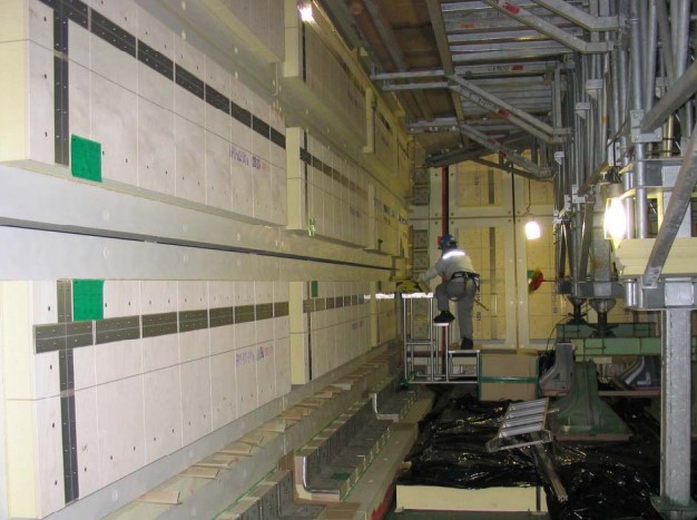
LNG panel Installation is a critical component in the construction of infrastructure for liquefied natural gas. These panels are engineered to provide exceptional thermal insulation and structural support, making precise installation vital for maintaining safety and efficiency. During the installation process, panels must be meticulously aligned and secured to create a seamless and continuous structure. This careful alignment is crucial to minimize thermal bridging and ensure that the low temperatures required for LNG storage are consistently maintained, preventing any loss of energy efficiency.
The LNG panel installation process ensures a secure and efficient setup for containment. Sealing these panels is equally vital, employing materials that can withstand extreme cold while maintaining a tight seal. The sealing process uses advanced techniques to ensure no LNG escapes and no heat enters, which is crucial for maintaining the liquid state of the gas and preventing boil-off. This combination of precise installation and effective sealing is fundamental for the optimal performance of LNG storage systems.
Panel Erection
LNG Panel Installation Procedure
This article outlines the detailed installation procedure for panels. (See Figure 1.)
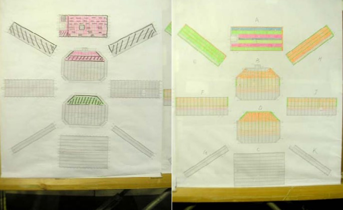
The normal installation sequence is: (See Figure 2.)
- Three way corner panes (trihedrons).
- Two way corner panels (90°, 135° or equivalent).
- Flat panels.
Prior installing the panels, the cleanliness of the inner hull is to be checked. Dust, grease and rust must be removed.
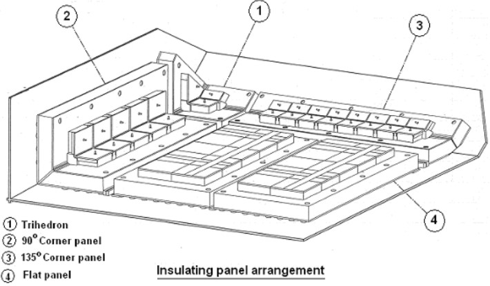
It is possible to start the flat area installation at the same time as the corner areas provided the borderlines of panel (3 m minimum) are installed after completion of the corner areas.
1) GENERAL CONTROL
For the installation of the panel and control of the maximum allowed open time (curing time) from epoxy mastic application until the final inspection, a check sheet will be placed on each panel including at least the following information:
- Identifying number of the panel.
- Time of epoxy mastic application.
- Type of epoxy bead/patch deposited.
- Time of the installation end.
2) TYPE OF BEADS/PATCHES
The type of epoxy mastic beads/patches has to be in accordance with the type given on the flatness program drawing.
3) ASYMMETRIC PANELS
In order to avoid installing a panel in the wrong location, panels (which are symmetric about bolt holes, but asymmetric about stainless steel anchoring strips) will have a symbolic position denoting orientation of the anchor strip marked on the inner hull.
4) GAP BETWEEN PANELS
Standard gap is provided between panels for ease of installation. After panel installation, this gap of 30 mm is filled with glass wool.
5) THREE WAYS PANEL ERECTION
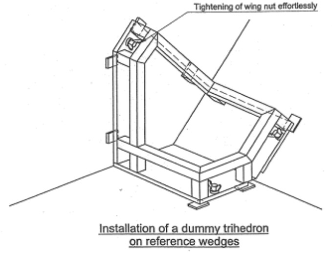
Because the three-way panel is the connecting piece between three adjacent bulkheads, and as it is the first installed, it is critical to adjust it accurately. To ensure this, a dummy trihedron with the reference surfaces (previously determined by reference wedges) is fit to confirm accuracy.
Two types of dummy trihedron will be fabricated corresponding to the actual types to be used (for tanks 2, 3 and 4, additional types will be made for tank 1).
The dummy trihedron will be positioned at the proper location and fixed by nuts on studs. The fitting must proceed effortlessly and without adjustment to confirm correct thiedron and location of reference wedges and studs. (See Figure 3.)
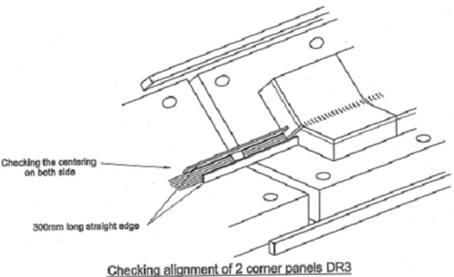
The alignment with the surrounding reference wedges will be carried out with a template. No excessive angle should be observed (tangent < 0,006). (See Figure 4.)
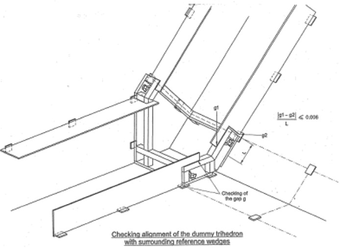
The same alignment check will be carried out with the trihedron after installation. (See Figure 5.)
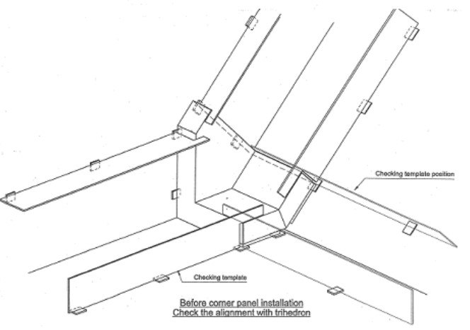
6) INSTALLATION OF 900 TWO WAYS PANELS
Because the trihedron and the adjacent corner panels on the edge do not have the same reference wedges, positioning of the reference wedges should be checked by means of template.
For general cases, prior installing a corner panel, it will be checked that no gap appears between reference wedges and the previously installed panel (trihedron or two way panel). If the gap > 0,5 mm an additional shim will be bonded to align the panels each other during erection. (See Figure 6.)
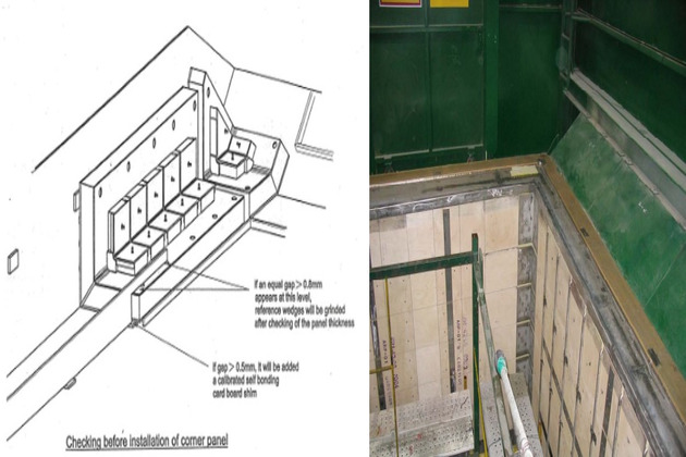
During installation, extreme care has to be taken not to disturb the mastic beads either against the inner hull plating or either against the retainer bar. Disturbed mastic beads will impair a good distribution of the load to the hull and that may lead to panel damage/collapse.
The tightening of the nuts on the studs has to be carried out with a torque wrench set properly set to avoid any damage to the panel bottom plywood.
7) INSTALLATION OF 135° TWO WAY PANELS
The same procedure as for the 90° two way panels is applicable.
Along the longitudinal corner, the hull plating can present large deformations. A checking of any possible deformation has to be carried out to confirm the size of the mastic beads given by the computer program. (See Figure 7.)
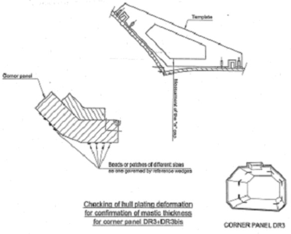
Additional checking will be performed with a template to check the alignment of the two panels in the radius. (See Figure 8.)
8) JOINT FILLER INSTALLATION
When trihedron and adjacent corner panels are installed, joint fillers can then be installed.
Joint fillers are previously cut at the width corresponding to the actual gap minus 30 mm. (See Figure 9.)
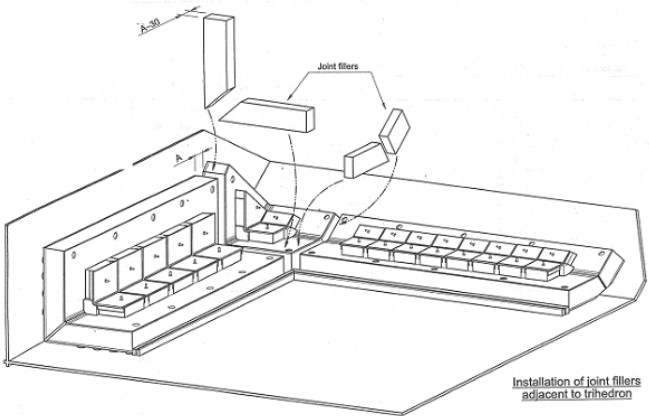
Join fillers are adhered to the steel hull plating with epoxy mastic of the same thickness as the three-way panel.
9) FILLING SPACES BETWEEN RETAINER BAR AND CORNER PANELS
After completion and curing of epoxy mastic under corner panels, it the space between the corner panels and the retainer bar are to be filled with plywood sections.
For 90° corner panels, a plywood strip of the length of the panel is first installed. This plywood strip is bonded with epoxy mastic or glue to the panel on one side and bias wood wedges are used to keep it in position during curing. After curing, the bias wood wedge can be removed or cut at the retainer level. (See Figure 10.)
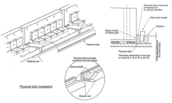
For all corner panels, the remaining gap is filled with epoxy mastic.
10) INSTALLATION OF FLAT PANELS
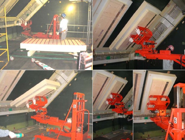
Because Key Characteristics of Membrane Tanks Systemsmembrane installation starts from top to bottom, to avoid dust during welding, panel installation should also start from top to bottom.
For a vertical bulkhead, panel will be installed from bottom to top; protection for any falling object or dust should be provided.
Installation of flat panel should be done with care to avoid damaging the mastic beads. Tightening of nuts should be done carefully with torque wrench as for other panels.
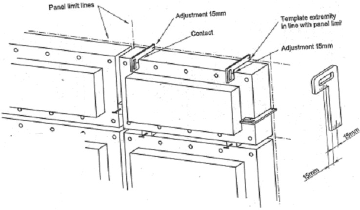
The panel must bear perfectly on the reference wedges and on the visible sides, the epoxy mastic beads/patches must be crushed. (See Figures 11 through 13.)
11) INSTALLATION TOLERANCES
- CORNER PANELS: TRIHEDRON AND TWO-WAY PANELS.
- Positioning tolerance according to panel limit lines: +/- 3 mm.
- Flatness between corner panels, secondary barrier level: +/- 1 mm.
- Gap between corner panels: +/- 3 mm.
- FLAT PANELS.
- Gap between adjacent panels: +/- 3 mm.
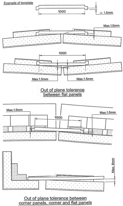
- Flatness between flat panel and corner panel at secondary barrier level: +/- 1,5 mm.
- Flatness between flat panel and corner panel at primary barrier level +/- 2 mm.
- Angular difference between panels (φ or β) is such that the tangent is < 0,006.
LNG Panel Installation Tolerance you can see Figure 14.
Cylindrical Foam Plug Installation
Once checking of panel positioning and checking of nut tightening are achieved, cylindrical foam plug can be installed.
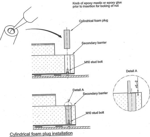
Cylindrical foam plugs are calibrated at the adequate diameter and height to fill up the stud holes in the panels. Prior to insert foam plug into the panel hole a knob of epoxy mastic will be put into the hole of plug for locking the nut stud.
No protrusion of plug is allowed. The allowable tolerance is = 0, -2 mm. (See Figure 15.)
Filling Gaps Between Panels
1) GENERAL
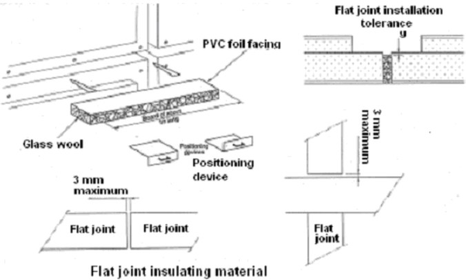
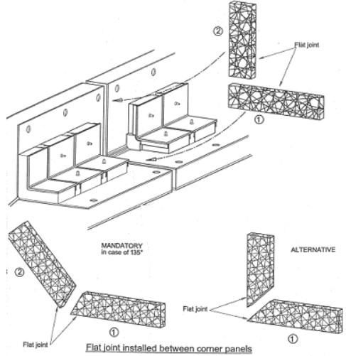
Flat joints made by glass wool provide a continuity of the insulation between panels. It must fill up completely the gap between panels. No gap in length or thickness should remain. The installation tolerance according to the secondary level is: 0,5 mm. (See Figures 16 and 17.)
2) JOINT FILLER AND FLAT JOINT BETWEEN CORNER AND BORDER PANELS
Prior to flat joint, it is necessary to install joint filler between corners and border panels.
According to MARK III System: Hull and Deck Components for Marine VesselsMARK III system design, the cargo hold tolerance are taken into account in the space between border panels and corner panels. Therefore the width of the space alongside the tank edges is variable.
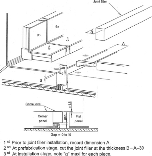
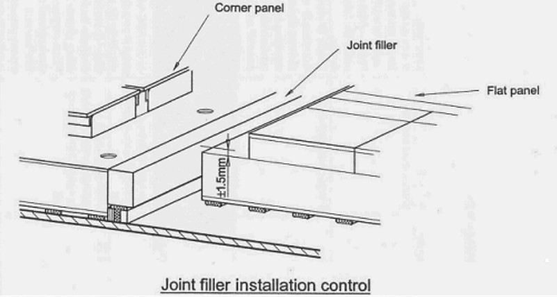
The thickness of the joint filler must be defined according to the space measured on board minus 30 mm. The cutting tolerance is governed by the gap tolerance between panels; +/- 3 mm in length. It is more suitable to have the joint filler in step with the corner panel in case of slight misalignment between corner panels.
After installation, it will be checked that the gap between joint filler and border flat panel is inside tolerance +/- 1,5 mm. (See Figures 18 and 19.)
3) FLAT JOINT BETWEEN JOINT FILLER AND FLAT PANEL
Flat joint will be inserted between the border flat panel and the joint filler. (See Figure 20.)
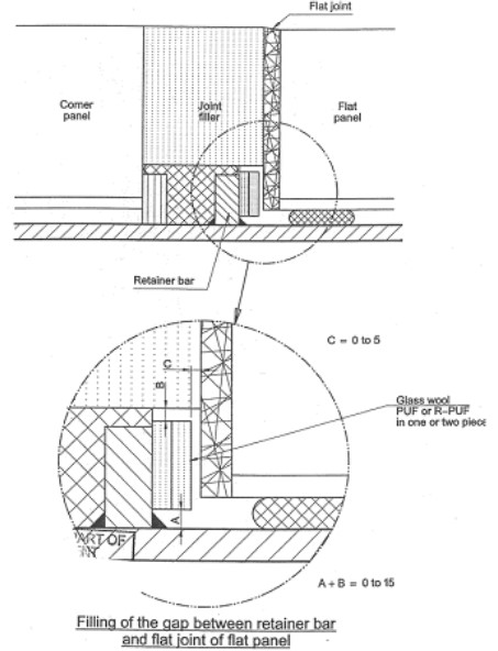
The gap between the retainer bar and the flat joint has to be filled if above 5 mm.
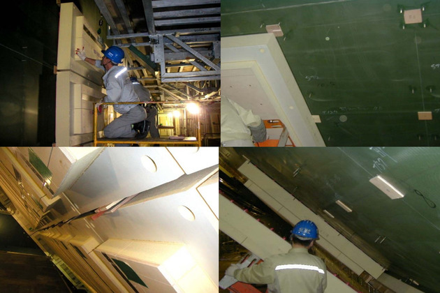
Figure 21 shows an hold bulkhead covered by installed panels.
