Membrane tanks systems excel through their flexibility, high-integrity sealing, and corrosion resistance, ensuring secure containment and minimizing risks. Modular designs simplify installation and maintenance, while maximizing volume efficiency and reducing system footprint. These features translate to enhanced safety, reduced downtime, and lower operating costs.
- Membrane Tanks
- General
- Secondary Barrier
- Streses on the Membrane System
- Common Main Features for the Membrane Tanks Systems
- Membrane Tanks Systems
- MARK III System
- MARK III System General Description
- Advantages of MARK III System
- Disadvantages of MARK III System
- NO.96 System
- NO.96 System General Description
- Advantages of NO.96 System
- Disadvantages of NO.96 System
- CS1 System
With broad applicability to diverse fluid types, membrane systems adapt seamlessly to various industries. Integrated level monitoring and control enable precise automation, and material compatibility ensures safe storage. The result is a robust, long-lived solution that balances performance, reliability, and economy. By leveraging these advantages, membrane tank systems optimize fluid management, streamline operations, and drive business value.
Membrane Tanks
General
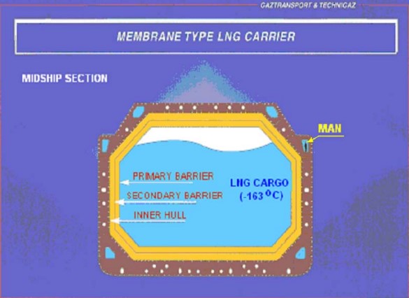
Membrane tanks are non-self-supporting tanks, which consist of a thin layer (membrane) supported through insulation by the adjacent hull structure. The membrane configuration is designed in such a way that thermal and other expansion or contraction is compensated for without undue stressing of the membrane.
The design vapor pressure Po should not normally exceed 0,25 bar. If however the hull scantlings are increased accordingly and consideration is given, where appropriate, to the strength of supporting insulation, Po may be increased to a higher value but no more than 0,7 bar.
The definition of a membrane tanks does not exclude designs such as those, which non-metallic membranes or in which membranes are included or incorporated in insulation. Such designs require, however, special consideration by the Administration. In any case, the thickness of the membrane should normally not exceed 10 mm.
Figure 1 shows a typical cross section of a membrane Top LNG Carrier Builders in Marine IndustryLNG carrier.
Secondary Barrier
A full secondary barrier is required for all membrane tanks.
The secondary barrier should be so designed that:
- It is capable of containing any envisaged leakage of liquid cargo for a period of 15 days, unless different requirements apply for particular voyages taking in account the load spectrum.
- It will prevent lowering of the temperature of the ship structure to an unsafe level in the case of leakage of the primary barrier.
- The mechanism of failure for the primary barrier will not also cause the failure of the secondary barrier and vice-versa.
Streses on the Membrane System
The system has to sustain the following stresses:
- Thermal stresses due to the low temperature.
- Ships stresses, global stresses, hogging/sagging.
- Local stresses:
- deflection due to ballast water and cargo;
- very high pressure of impact at the level of the free surface of the liquid cryogenic cargo.
For a large ship with a capacity of 130 000 m3 and over, under extreme bending condition, deflection of as much as one meter on an underwater hull 280 m long may be detected.
Also, when the wave action is ¾ forward, the underwater hull tends to twist, inducing torsion in the carrying structure of Independent Cargo Tanksthe cargo tanks.
At sea, the combined movements of the ship will generate various accelerations capable of reaching values of 1,6 to 1,8 G vertically. These accelerations create cyclical hydrodynamic pressure on the ship’s double hull, as induced by the cargo during voyages on load or by seawater and lateral ballast loads during voyages on ballast. This pressure may reach high levels, around 3,5 bars for the ballast and at most 3 bars for the cargo condition. It can cause deformations of severalmillimeters in the double hull, and, over large surfaces the deformations can reach several centimeters.
«The ship structural design is calculated to keep the level of stresses within the limit acceptable for the insulation system. The membrane designer sets these limits for the various types of containment systems.»
As the membrane tank is a non-self-supporting tank, all the loads are transmitted to the adjacent structure.
The contact between adjacent surfaces of elements of membrane systems and to supporting structure of inner hull must be in accordance with design. Failure to achieve adequate contact of elements in the chain can increase local loading and may cause failure of some component of the membrane system.
Common Main Features for the Membrane Tanks Systems
A membrane function is to provide a non-permeable layer to insure tightness and does not possess any significant structural strength. Due to the relatively this and flexible properties, membranes are very sensitive to pressure differentials.
The pressure differential between the secondary spaces and the primary spaces is:
The pressure differential between the primary spaces and the cargo spaces is:
Of course, Pcargo is the pressure of the cargo, Pprim in the pressure in interbarrier space (primary barrier space) and Psec is the pressure in the insulation space (secondary barrier space).
The pressure differential should not exceed 20 or 30 millibar according the type of containment system. In general the following relation between the above pressure should be assured in all operative conditions:
If the pressure differential exceeds the above values, the membrane may collapse. NO.96 system is particularly sensitive to pressure differential.
Due to high sensitivity of the membrane to pressure differential, pressure and differential pressure indicators and alarms as well as pressure regulation devices are fitted. On top each space (secondary, primary and cargo) two pressure relieve valves are fitted. Set points for the valves are functions of the protected space and the cargo containment system.
Note that cargo safety valves open not only by high pressure (240/250 millibar) but also by low pressure (-10 millibar). That is the last resort means to avoid the membrane failure in case of drop of pressure in the cargo tanks. The lift of the safety valve at -10 millibar would allow the entry of air in the cargo tank and make the environment unsafe. As a safety measure, in such case, cargo pumps (submerged type) are shut down by cargo tank low pressure. The gas compressor must also shut down by low pressure.
Membrane Tanks Systems
At the present time there are three systems (only one designer – GTT) used for the gas containment system of LNG carriers.
- Mark III system (Samsung, NKK, HHI, Imabari).
- NO.96 (Daewoo, Mitsubishi, Mitsui, Chantiers de l’Atlantique, Izar, Fincantieri, Hudong).
- CS1 (Chantiers de l’Atlantique).
MARK III System
MARK III System General Description
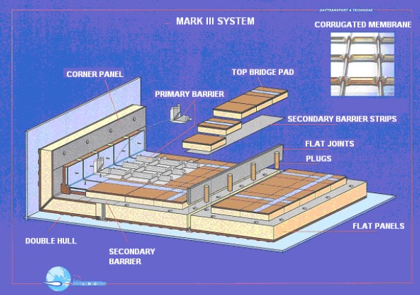
The primary membrane is a 1,2 mm thick stainless steel corrugated membrane. There are corrugations in both directions (forward-aft and port-starboard) allowing the membrane to act as a bellow in both directions, therefore the level of stress is very low. Corrugations and nodes between perpendicular corrugations are made cold forming the stainless sheet without any expansion or thinning of material.
The stainless steel corrugated primary membrane is fit and welded to stainless steel strips built into insulation panels. The insulation panels are held to the inner hull by bolting with resin ropes and plywood space pieces to compensate for any unevenness of the inner hull and to provide space for nitrogen purging.
The membrane is laid on insulation panels, which are supported by the inner hull through resin beads, which compensate the lack of flatness of the inner hull and also provide the space between the inner hull and the insulation for nitrogen purge.
The secondary membrane is composed of a continuous layer of triplex material (aluminum foil sandwiched between two fiberglass sheets). Triplex is made continuous by gluing “supple triplex” in way of top bridge pads and corners.
The insulation panels are made of three layers glued together:
- one 160 mm thick polyurethane foam reinforced with fiberglass mat board;
- one triplex layer that becomes the secondary barrier;
- one 80 mm thick polyurethane board.
The panel is completed with two 8 mm thick plywood boards: one per each side.
The polyurethane foam constitutes the insulation. This foam must have following properties:
- Resistance to compression must comply with a required value in order to transmit the load to the inner structure without collapsing.
- Insulation panels must deform with inner hull as vessel flexes. In order to retain sufficient strength, the panels are reinforced with fiberglass mat when formed and are adhered to inner hull using mastic resin rope (beads) directly connecting to steel surface.
However the stress in the foam should be kept under a certain value and the adjacent structure is to be designed accordingly. (See Figure 2.)
Advantages of MARK III System
1) CORRUGATE MEMBRANE
The membrane is low stressed, provided erection tolerances are complied with.
2) 1,2 mm THICK MEMBRANE
Membrane thickness is greater than that of other systems and is less likely to be damaged during erection as throughout life of vessel.
Disadvantages of MARK III System
1) GLUED ASSEMBLY
Assembly of system relies on adhesives (mastic for panels to hull, glue for top bridge pads), which, once cured, can only be removed by destroying the insulation components.
2) HIGH PRICE OF THE FOAM
Fiberglass reinforced polyurethane foam panels, complete with triplex, plywood and stainless strips, are very costly.
NO.96 System
NO.96 System General Description
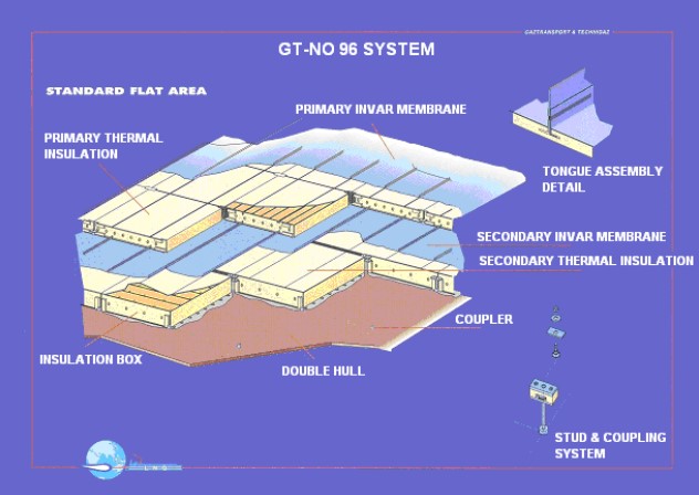
This system is based on two identical invar membranes. Invar is a 36 % nickel alloy with a very low shrinkage coefficient about 10 times less than the steel (1,2 × 10⁻⁶ m/m/°C).
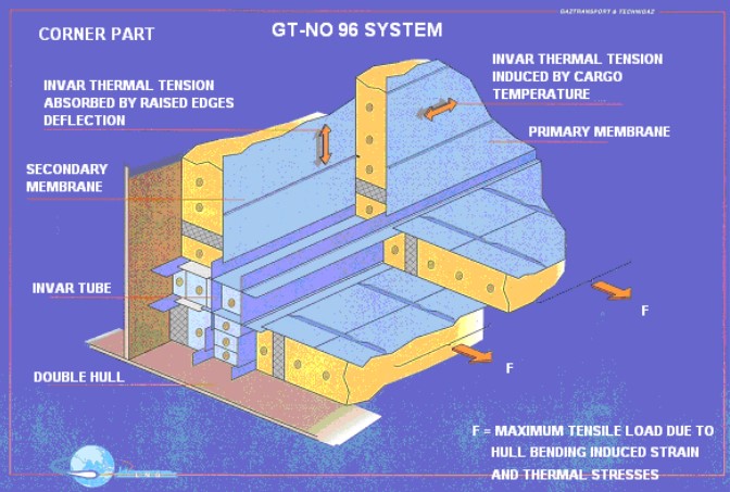
This very low shrinkage coefficient reduces the thermal stress induced from cool-down and cryogenic temperatures. However, thermal stresses are still present and when combined with ship deformation stresses (local and global), present the major engineering challenge for the designers.
The maximum stress is limited by invar strength and welding joint strength (strake to corner pieces). The Evolution of Boat DesignThe ship structure is to be designed taking all this into account.
For each strake, the transversal stress is absorbed by the raised edge joints, which act as bellows with low level of stress, provided that the strakes were laid down within designer’s tolerances.
The containment system comprises from the inner hull:
- the secondary insulating element;
- the secondary membrane (invar);
- the primary insulating element;
- the primary membrane (invar).
The insulating elements (primary and secondary) are plywood boxes filled with perlite, which is an expanded silica based insulation material. The secondary boxes are set against the inner hull trough resin beads, which compensate the lack of flatness of the inner hull and also make room for the passage of the nitrogen purge. However, a significant difference between MARK III system and NO.96 is that boxes are not glued to the inner hull. A sheet of brown craft paper rests between the resin and the inner hull to allow the boxes free movement for hull deflection. See Figures 3 and 4.
Advantages of NO.96 System
1) INSULATION CHEAP AND EASY TO MANUFACTURE
- Plywood boxes are relatively easy to fabricate with quality being a crucial feature as far as external box spacing of internal partitions and accuracy of stapling.
- Perlite is inexpensive and easy to manufacture, even if granulometry is crucial.
2) WELDING OF INVAR MOSTLY CARRIED OUT USING AUTOMATIC WELDING MACHINES.
3) PRIMARY AND SECONDARY MEMBRANES ARE NEARLY IDENTICAL.
4) INSTALLED SYSTEM CAN BE REMOVED AND REINSTALLED WITHOT DESTROYING THE INSULATION BOXES.
Disadvantages of NO.96 System
1) INVAR IS MORE COSTLY THAN OTHER MATERIALS.
2) INSTALLATION OF TWO IDENTICAL MEMBRANES REQUIRES SIGNIFICANT LENGTH OF TIME.
3) ERECTION OF SYSTEM REQUIRES ACCURACY AND MAY BE DIFFICULT AT SPECIFIC AREAS OF THE TANK.
4) INVAR, BEING 0,7 MM THICK, IS MORE SUSCEPTIBLE TO MECHANICAL DAMAGE.
CS1 System
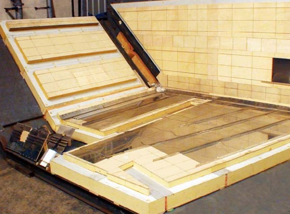
CS1 is a combination of MARK III system and NO.96 system set up to cut cost. (See Figure 5.)
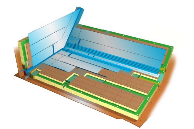
The insulation and the secondary membrane is the MARK III system (polyurethane foam and triplex, glued assembly) and the primary membrane is the NO.96 system (invar). The corner assembly is very similar to the NO.96 system corner assembly.
This system is quite new; the first LNG carrier (70 000 m3) with this system is under completion and should be delivered soon by Chantiers de l’Atlantique. A second ship (155 000 m3 ) is on order at the same shipyard.
As this system was set up for cost cutting purpose, it combines the cost effectiveness of one system with the ease of installation and testing of the other.
- Only one (1) invar membrane (gain of one).
- Less number of insulation panels to manufacture and install but more expensive.
According GTT, CS1 is about 15 % less expensive than MARK III or NO.96.
Figure 6 is the photograph of a mock-up of the CS1 system.
