LNG tank design and the cargo containment system are fundamental elements of LNG carrier construction, ensuring the safe and efficient transport of liquefied natural gas (LNG) across vast distances. The LNG tank design encompasses various aspects, including materials selection, insulation, and structural integrity. These tanks are typically constructed from high-grade stainless steel or nickel-alloyed steel, featuring double-walled structures with advanced insulation to maintain LNG at cryogenic temperatures. Additionally, LNG tanks incorporate safety measures such as pressure relief systems to prevent overpressurization and rupture, safeguarding both the cargo and the vessel. The cargo containment system, on the other hand, refers to the arrangement within the vessel that securely houses the LNG cargo during transit. Various containment systems, such as membrane, spherical, or prismatic designs, are employed, each offering unique advantages in terms of space utilization, stability, and safety. These sophisticated engineering solutions ensure the integrity of LNG storage and transportation, meeting stringent safety standards and environmental regulations in the maritime industry.
- Type “A” Tanks
- Conch Design
- ESSO Design
- Type “B” Spherical Tanks
- Features of Moss-Rosenberg Ships
- Design Criteria for Spherical Tanks
- Sphere Assembly
- Welding
- Insulation
- Pump Tower
- Partially Secondare Barrier (DRIP TRAY)
- Finite Element Analysis for Gas Carriers Fitted with Type “B” Tanks
- Design Consideration Resulting from Analyses of Spherical Tanks
- Technological Developments and Future Trends
Conch design represents a cutting-edge approach to LNG tank design, characterized by its innovative use of reinforced concrete materials and unique geometric configurations. Developed by Conch Design Institute, this novel design offers several advantages, including enhanced durability, cost-effectiveness, and reduced environmental impact compared to traditional steel-based tank designs. Conch design incorporates advanced construction techniques to optimize structural integrity while providing excellent insulation properties to maintain LNG at cryogenic temperatures. Additionally, its modular construction allows for scalable implementation across various vessel sizes, offering flexibility and adaptability to different shipping requirements. With its combination of robustness, efficiency, and sustainability, Conch design sets a new standard for LNG tank design in the maritime industry, promising safer and more reliable transportation of liquefied natural gas worldwide.
Type “A” Tanks
Conch Design
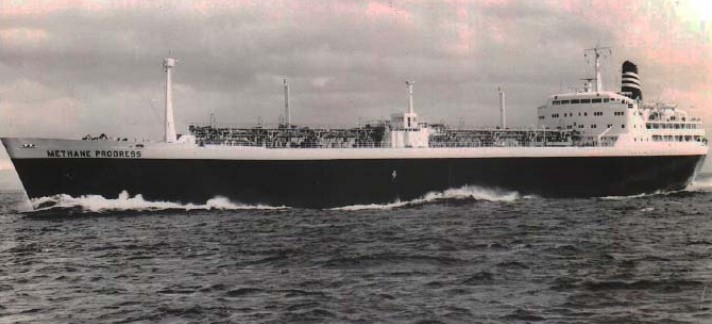
Figure 1 is a photograph of “Methane Progress“. This 27 000 m3 capacity ship was the first LNGC used for regular trades across Atlantic Ocean. The ship was scrapped in 1997 after 33 years of service.
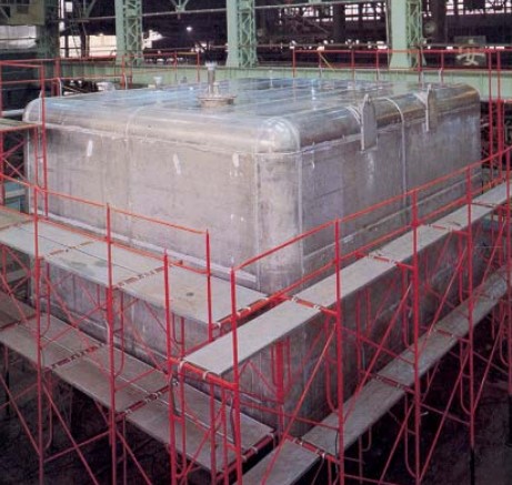
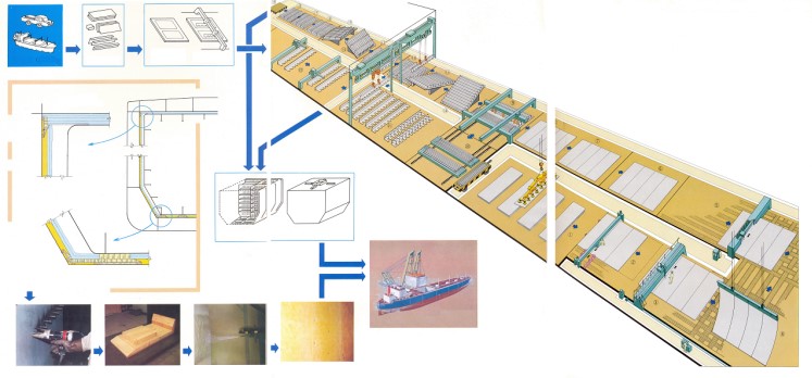
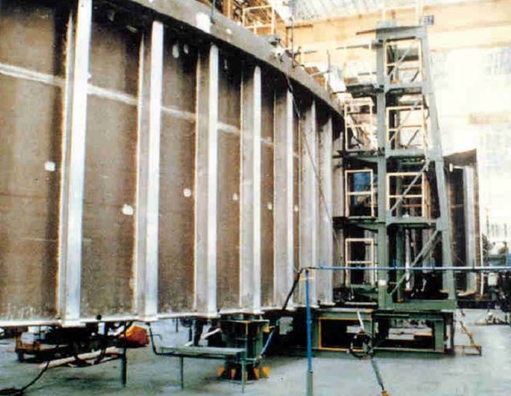
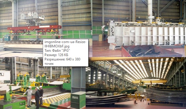
As anticipated in LNGC Project Factors and Cargo Containment SystemCargo Containment Systems for LNG Carriers and Cargo Operation – General, the cargo containment system of this ship was made of type “A” independent tanks of CONCH design. CONCH system consisted of prismatic aluminum tanks with secondary barrier of plywood/balsa. Figures 2 and 3 show a typical CONCH tank built in Japan, as well as a drawing showing the production line for the construction of CONCH tanks.
ESSO Design
Figure 4 is a photograph of “Esso Brega“, a 41 000 m3 capacity LNGC built in the late 1960’s, still in service renamed “LNG Palmaria“.
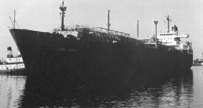
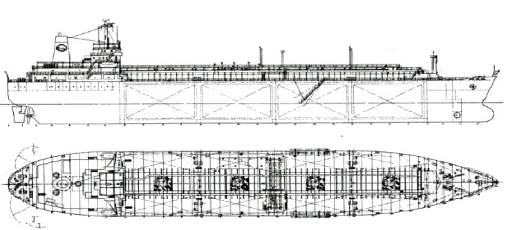
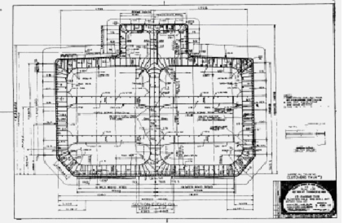
The cargo containment system, designed by ESSO, is made of type “A” independent tanks. Figure 5 is the general arrangement plan of this ship.
Figures 6 and 7 show her Midship Section. The quality of drawings is a result of having been taken from forty-year-old microfilm.
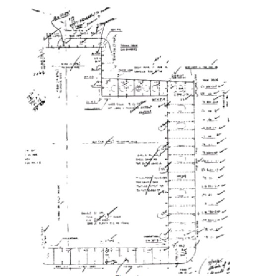
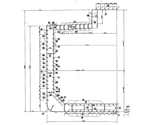
The four tanks are aluminum and a complete secondary barrier is provided. The four ships of this design are the last LNGC built with type “A” independent tanks. Figure 8 is the midship section of one of these tanks.
The vessels performance in service has been excellent. The only reported defect was a typical fatigue crack developing in proximity of a side stringer corner bracket in the cargo tank. It was a classic example of fatigue cracking, as it was observed in all four ships same location, about at the same time after 20 years of service. Even though this design was successful, no other ships with type “A” independent tanks have been built due to their cost and the necessity to provide a complete secondary barrier.
Type “B” Spherical Tanks
Features of Moss-Rosenberg Ships
For over 20 years, the only design of type “B” independent tanks has been the Moss-Rosenberg design.
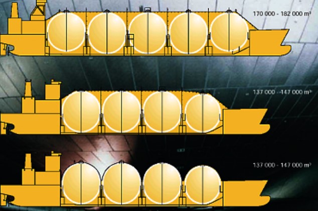
The spherical tank concept is due to Moss Rosenberg and was licensed by Kvaerner, so the concept is also known as Kvaerner-Moss. The first generation of 125 000 m3 Top LNG Carrier Builders in Marine IndustryLNG carriers was built with 5 spherical tanks of 36,6 m diameter, though 2 ships were built with 6 tanks. Most recent designs have 4 tanks of over 40 m diameter.
The cargo containment system is made of an unstiffened spherical tank supported at the equator by a vertical cylindrical skirt. The bottom of the cylindrical skirt is welded integrally to the ship hull structure. The skirt is attached to the equator of the sphere by welding a specially shaped section. Figure 9 shows a sketch of a typical Moss-Rosenberg arrangement.
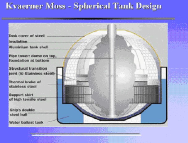
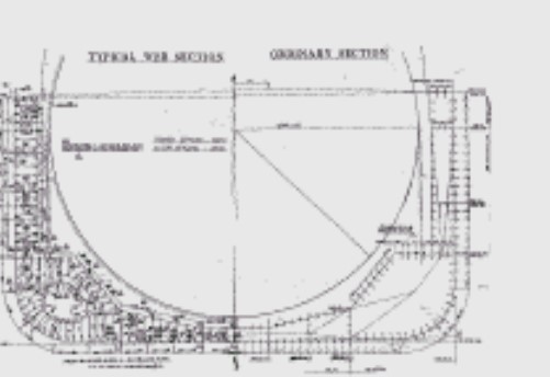
Figure 10 shows a typical midship section.
The tanks fitted on the first LNG ships with spherical tanks, the “NORMAN LADY” and “ASAKE MARU“, were made of 9 % nickel steel. All ships built after these vessels were fitted with aluminum tanks.
The skirt supporting the tank transmits all the loads from the tank to the hull. In addition the thermal contraction of the tank due to the low temperature is absorbed by the deformation of the upper half of the skirt. This particular skirt support prompts emphasis on an engineering analysis of the junction between the tank shell and the supporting skirt as well as the region below the skirt where the sphere interacts with the hull structure under various combinations of static, dynamic and thermal loads.
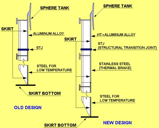
The upper part of the skirt is of the same material as the tank and lower part is of carbon-manganese steel. The transmission joint between aluminum alloy and carbon manganese steel is made by expansion bonding. In the latest designs a stainless steel thermal brake has been introduced in the carbon-manganese steel portion in order to reduce the heat losses in the skirt. Figure 11 is a sketch of skirt details.
Design Criteria for Spherical Tanks
The basic design criteria for the spherical tanks are contained in the The Origins of the IGC CodeIGC Code. The modern techniques for analyzing structures, advanced fatigue analysis, fracture mechanics and quality control enable these tanks to be qualified as “B“: tanks. Accordingly only partial secondary barrier is required for this type of cargo containment system.
LNG is carried at about -163 °C and near atmospheric pressure. These tanks are generally designed for 2 kg/cm2 pressure, so that they may be unloaded by pressurizing the tank in case of failure of both cargo pumps.
Sphere Assembly
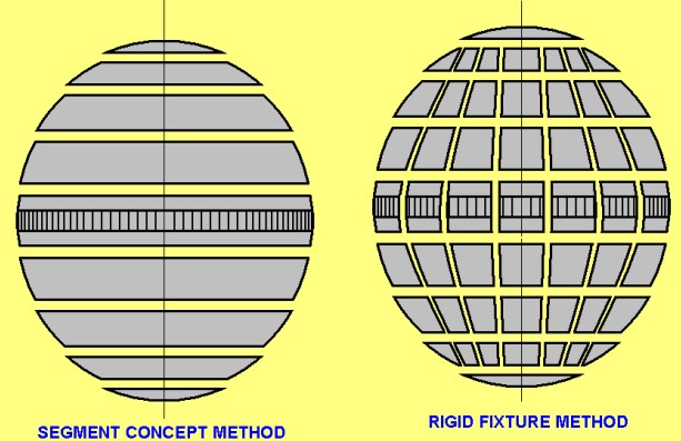
The spheres are manufactured using two different methods. With the “segment concept” method, the sphere is sliced horizontally into a number of circular sections. The sections are fabricated from plates welded together into 360-degree rings. Finally, assembly takes place by stacking and welding the sections together. In the segment concept method the tank is erected in the hold space, generally in three prefabricated sections:
- lower hemisphere;
- equatorial section with skirt;
- upper hemisphere.
After the tank covers are installed, welding of the sections is carried out in a controlled environment.
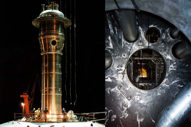
With the “rigid fixture concept” method, complete assembly of the sphere including the installation of the insulation is carried out in a special workshop in the same yard where the vessel is built or in different location away from the shipyard (see Figure 12).
The following figures show manufacturing and installation of the spheres for two ships built in two different yards (from Figure 13 to Figure 25 the first yard and from Figure 26 to Figure 38 the second).
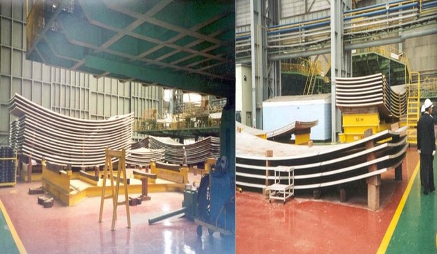
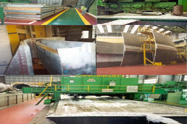
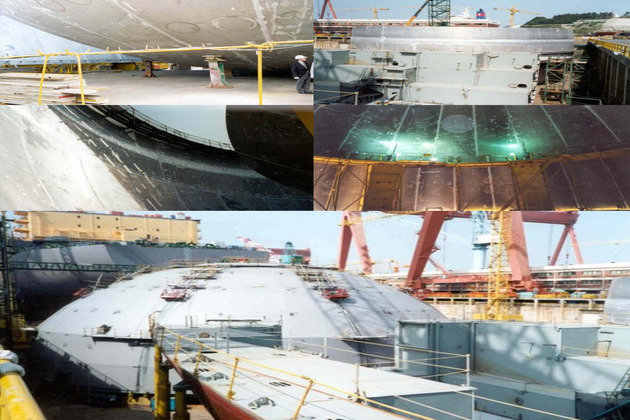
Figures 13, 14 and 15 show the sphere plating forming and the welding of the formed plates.
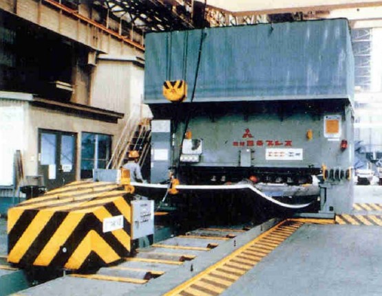
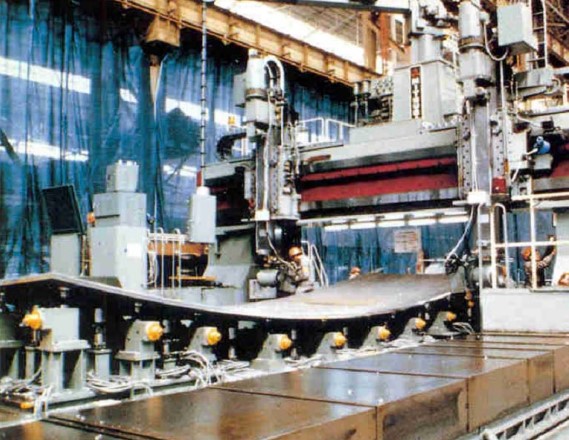
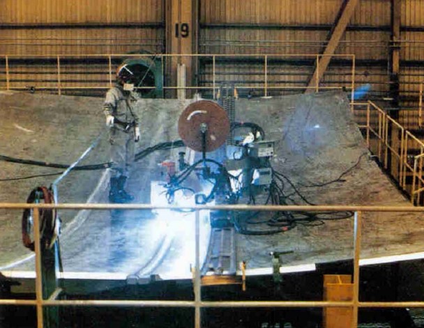
Figure 16 shows the skirt supporting the sphere tank ready to be installed on board.
Figures 17 and 18 show the upper part of a sphere tank assembled in the workshop (including the dome) and just after installation on board.
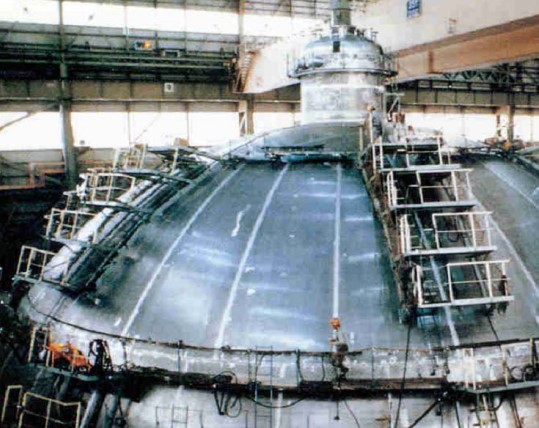
Figures 19 and 20 show the installation of deck covering above the sphere tank on board and the welding of the sphere tank sections on board.
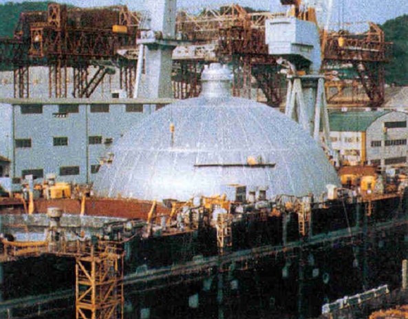
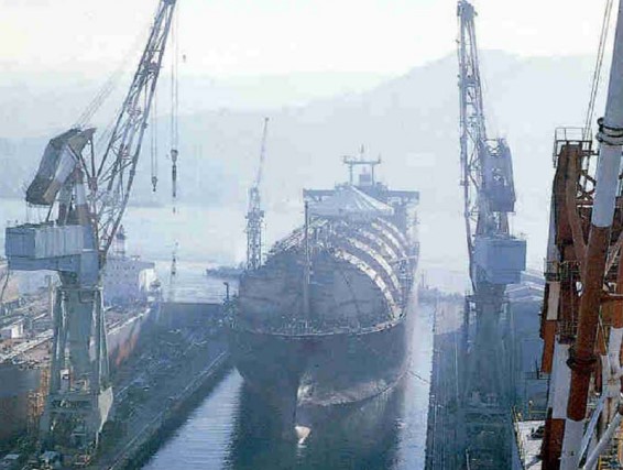
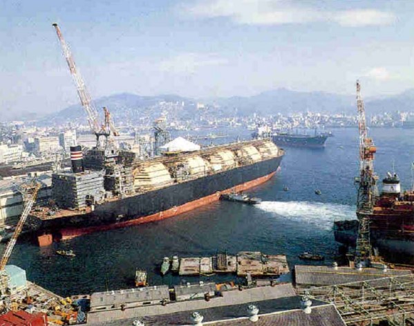
Figures 21 and 22 show the ship after the assembling of the sphere tanks and the deck covering during launching and at dock during outfitting.
Next Figures 23, 24, and 25 show the deck of the ship with tank covers, domes and cargo piping and the side passageway in the double hull.
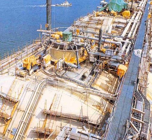
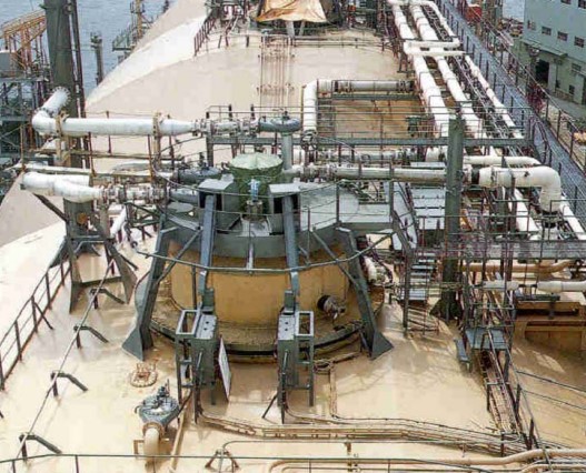
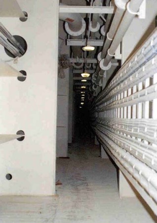
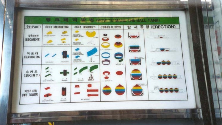
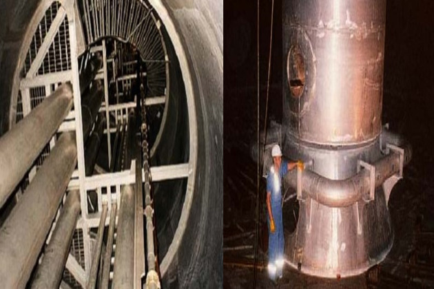
Figure 26 shows the building and assembly sequence for a sphere tank and its supporting skirt.
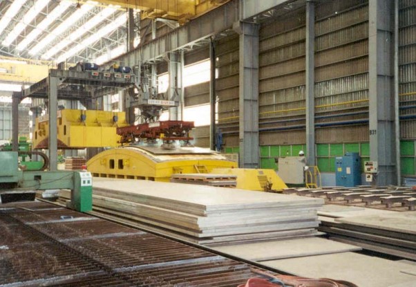
Figures 27 through 29 are relative to forming the plates for the construction of the tanks and the skirts.
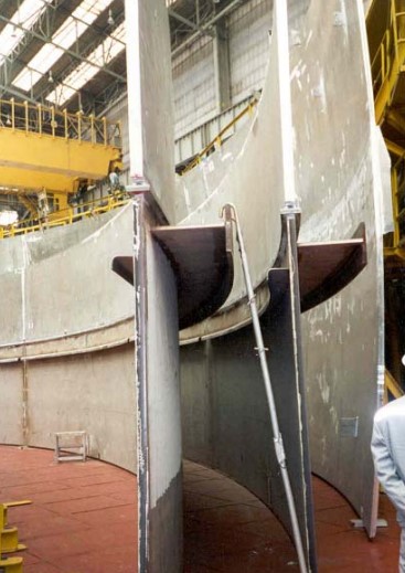
Figures 30 through 31 show the fabrication of the connection piece between the sphere tank and the skirt, as well as the structural transition joint in the skirt. The thickness of this piece is in the order of 160 mm.
While the thickness of the other sphere plates is in the order of 30-35 mm (Figure 31).
Figures 32 shows two views of the prefabrication shop.
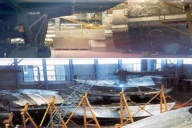
Figure 33 shows the installation of the spheres on board.
Finally, Figure 34 shows the ship after construction.
Welding
The following is a short description of the welding carried out for the construction of the first aluminum spheres built by General Dynamics in Charleston, S. C on 1976. They were built to criteria established by the U. S. Coast Guard and were based on Section VIII, Division 1, of the ASME Code.
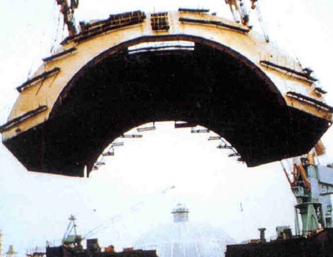
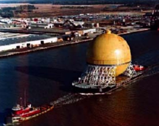
The sphere weighed 850 tons and measured 120 ft (36 m) in diameter. It consisted of more than 100 precisely machined plates, “orange peel” in shape. The plates were gas metal arc welded together using 7036 lb (3166 kg) of filler metal. Total length of the welds on each sphere was 48,6 miles (78,2 km). Completed spheres moved over to a special stand for final hydropneumatic testing and then were barged along the coast and delivered for installation onto steel hulls under construction at General Dynamics’ shipyard in Quincy, Mass. Figure 35 shows the complete sphere.
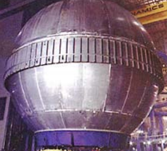
Figure 36 shows the sphere being shipped to the shipyard.
At General Dynamics’ facility in Charleston, 80 % of the metalworking man-hours were spent welding. Much of the filler metal deposited in Charleston was 5183 aluminum alloys. The vertical joints were welded using special equipment from Switzerland in which the operator rode in a custom-designed chair alongside the welding arc. At this distance, he was able to monitor the weld and observe the oscillation of the 1/16-in. (1,5-mm) diameter filler metal. Actual welding was controlled remotely. About 30 weld passes were required for each joint.
The thicker 11/2-in. (3,8-cm) joints were welded by large Metal Inert Gas (MIG) equipment, operating with a 1/8-in. (3-mm) diameter wire at 500 A. The equipment was capable of completing the joint in four passes.
The massive equatorial ring was welded outdoors. In this setup, nine heavily machined, curved aluminum extrusions had to be welded together. To accomplish this, 88 GMA weld passes were made from the outside and 60 more from the inside. For more information on characteristics and welding of aluminum and aluminum alloys reference may be made below to this article.
Insulation
Two methods, both based on foam materials, are used for insulating the spherical tanks; these are panel and spiral generation.
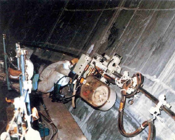
In the panel method, insulating panels made of modified polyurethane foam, polystyrene or a combination layer of phenolic resin foam and a layer of polyurethane foam are attached onto the spherical tank with a number of equally spaced studs. A vapor barrier of aluminum foil or polyurethane/butyl rubber composite coating is applied in the outer surface. In order to allow the necessary shrinkage in the horizontal and vertical directions, expansion joints are provided in each panel. As reinforcement and crack arrestor, glass cloth is integrated into the polyurethane panels or a wire mesh is fitted between the panel of phenolic resin foam and the polyurethane foam. Figure 37 is a photograph taken during the installation of the insulation.

In the spiral generation method (Figure 38) a special polystyrene log is spun onto the tank.
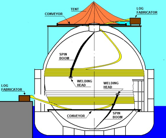
The base material is expanded polystyrene foam with glass fiber mesh cloth reinforcement. The vapor barrier is made of aluminum foil. The system also includes expansion joints that form an integral part of the insulation. The spiral generation method is highly automated insulation application system, which offer several advantages, such as:
- reduced manpower,
- rapid application,
- continuous monitoring,
- uniform quality.
Short insulation logs are fabricated from foam boards by thermal lamination. The short logs are thermally butt-welded to long logs and the long logs are then conveyed to the spinning head. The spinning head is automatically driven along a rotating arc boom to locate the foam in a continuous spiral over the tank surface without being permanently fixed to it. A welding pattern in the spinning head thermally seals the incoming log surface to the previously applied material. At the same time, the aluminum foil used as vapor barrier is sealed by heating and pressing an overlap to the previously applied material. Straps and steel springs secure the insulation to the lower hemisphere and a flexible membrane ring of elastified polystyrene connects the insulation surface of the lower hemisphere and the insulated inner side of the skirt.
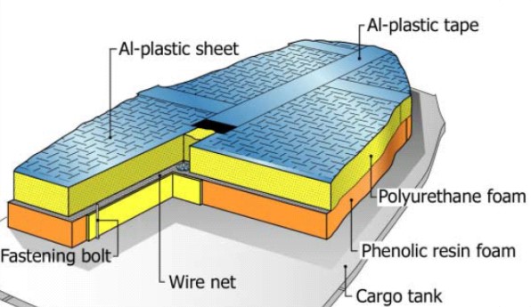
In both methods, the insulation is not bonded to the tank surface. This allows continuous monitoring of the interspace for gas leakage, action as spray shield for hull and directs any leak downward to the drip tray that forms the secondary barrier. Figure 39 shows the most update insulation system developed by Kawasaki. Kawasaki states that with this system they succeeded to keep the boil-off rate below 0,10 % per day.
Pump Tower
Within each tank the pumps and filling lines are arranged on column structure fitted in correspondence of the vertical axis of the sphere. The pump column is supported by the liquid dome and anchored to the tank top through a sliding pinned connection. The tower contains the two main Use of Cargo Pumps on Liquefied Gas Carrierscargo pumps, the stripping pump, the filling lines and the risers. The structure of the pump column is also used to accommodate the ladders for the access to the tank.
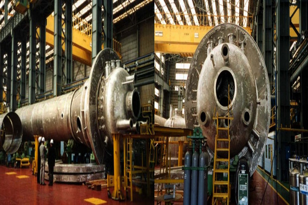
The following Figures 40 through 42 show pump towers during fabrication at workshop, during and after installation on board.
Partially Secondare Barrier (DRIP TRAY)
A drip tray forms the secondary barrier required under the IGC Code for type “B” tanks and it can safely contain the liquid natural gas as it evaporates. The drip tray is arranged in the inner bottom under the lower part of the cargo tank and is separated from the tank top by insulated supports. The drip tray is made of stainless steel or of the same material of the tank that, in general, is 5083-0 aluminum. The top all around is provided with flanged coamings and internally baffled plates are fitted to restrict the movement of any liquid resulting from heel, trim and motions of the ship. The drip tray is so designed that is capable of containing the maximum assumed tank leakage as determined from the fracture mechanism analysis for a period of 15 days. Figure 43 shows the bottom of a sphere tank after installation and the position where the secondary barrier is installed.

Installation
Finite Element Analysis for Gas Carriers Fitted with Type “B” Tanks
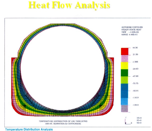
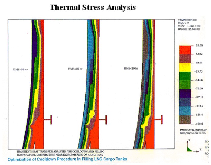
As already mentioned the sphere tanks are supported at their equatorial ring by a continuous cylindrical skirt, which is welded to the hull structure. This particular support system prompts emphasis on examining the junction between the tank shell and the supporting skirt as well as the region below the skirt, where the sphere interacts with the hull structure under various combinations of static, dynamic and thermal loads. Figures 44 and 45 show a typical temperature flow analysis and thermal stress analysis in way of the connection between the tank and the skirt.
As SAFEHULL is not available for sphere tank ships, these ships are analyzed using DLA approach.
A ship motion and long-term statistical analysis is performed to determine the wave-induced acceleration forces hence pressures and moments on a ship moving in a seaway of various headings.
In particular, an analysis is to be carried out on the spherical tanks to analyze:
- Membrane and bending stress due to symmetric and asymmetrical loads.
- Buckling of spherical shells.
- Vibration analysis of spherical shell.
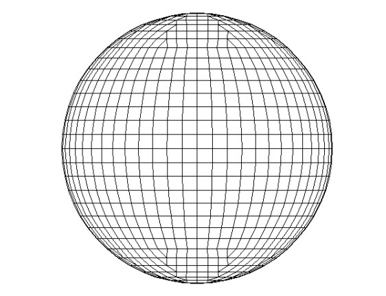
Figure 46 shows a typical mesh for the analysis of a sphere tank.
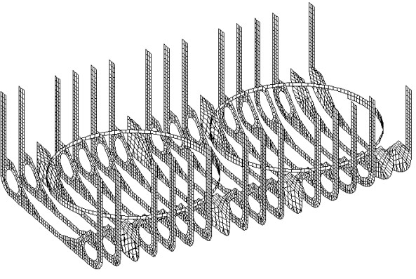
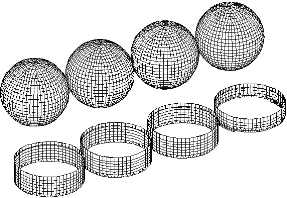
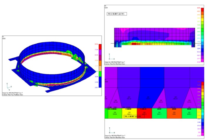
Of particular importance is the interaction at the interface between hull and spherical tanks through the cylindrical skirts. Figures 47 through 49 show the meshes for the analysis and some examples of results, (including zooming) for these important details.
Design Consideration Resulting from Analyses of Spherical Tanks
The results of the Engineering analysis on the spherical tank ships lead to the following general considerations:
a) BUCKLING
The actual buckling pressure is found to be 20 % of the pressure which would produce actual buckling and this value is used in the sphere analysis. The following loads, which produce compressive membrane stresses in the tank shell are examined:
- Weight of shell and weight of insulation.
- External pressure.
- Flooded condition in case of hull flooding (with empty tanks).
- Partially loaded tanks.
b) STRESSES IN THE HULL STRUCTURE
The maximum longitudinal stress is found on the inner side of the main deck and is produced by the combined actions of static and dynamic bending moments and water pressure acting on the side shell. The analysis indicates that the stresses at the lower part of the hull are low except for stress concentrations in the region below the skirt.
Technological Developments and Future Trends
The most important technological developments of the Moss Rosenberg spherical tank containment systems are:
- Reduction of number of cargo tanks from 5-6 to 4.
- Thicker insulation.
- Stainless steel thermal brake inserted between the aluminum alloy unit and steel unit. Since stainless steel has much lower thermal conductivity compared to steel, the heat losses through the skirt are reduced.
- Increased capacity.
The new trends towards larger and large LNG carriers led Kvaerner to design a new generation of Moss-Rosenberg ships with cargo capacity above 200 000 m3 (See Figures 50 and 51).
The main characteristics of these new concept designs are:
a) Stretching the dimension of the spheres as much as possible. However after the spheres have reached a certain dimension, the only way to increase the cargo capacity is to pass from the 4 tanks to the 5 tanks configuration (see Figure 51).
b) Adoption of the diesel-electric propulsion system and azimuth POD’s to reduce as much as possible the engine room space and to reduce the fuel consumption, this purpose being also obtained by an improvement of the hull forms and consequent reduction of hydrodynamic resistance.
c) Reduction of the boil-off and installation of a reliquifaction plant.
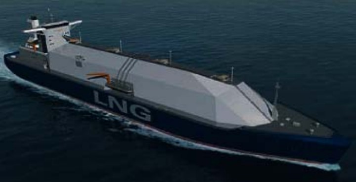
d) Adoption of a continuous structural tank covering, instead of the typical semi-sphere coverings of today’s Moss-Rosenberg ships (see Figure 50). This is necessary as, due to the increase of the ship lengths (five tanks instead of four), it would be almost impossible to satisfy the longitudinal strength requirements just reinforcing the narrow strip of deck existing outside the large openings for the cargo tanks. The proposed large trunk will be the strength deck of the ship.
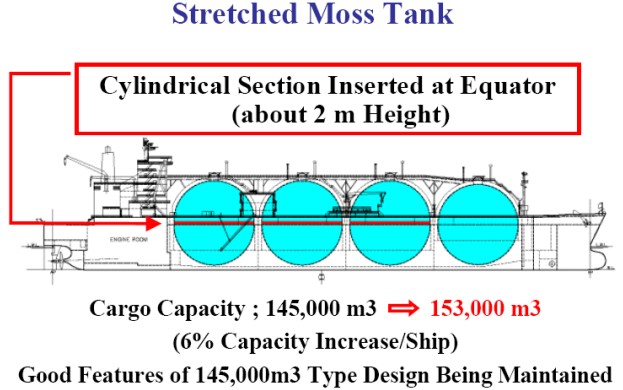
Also Kawasaki has developed projects for larger Moss-Rosenberg LNG carriers. Figure 52 shows the evolution of the Kawasaki design from today’s standard size (145 000 m3) to 200 000 m3.
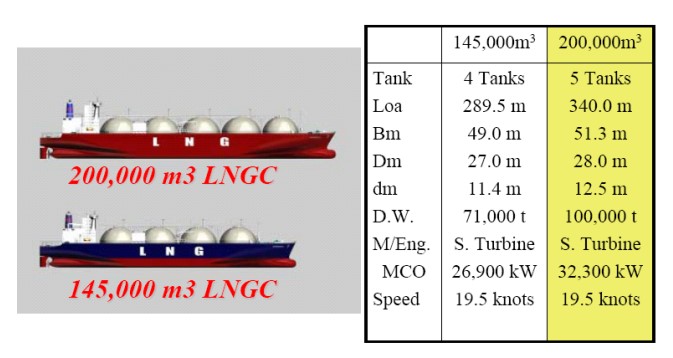
Figure 53 shows another Kawasaki proposal to increase by 8 000 m3 (6 %) the capacity of their 145 000 m3 design without changing the overall dimensions of the vessel.