Within the oil and gas industry there are inherent risks of accidents occurring at any stage of the process – from exploration through to the extraction, refining and final delivery of the product. These risks include fire, explosion, environmental contamination and injury to personnel. This article covers info about Risk Management Process.
- The purpose and uses of risk assessment techniques, qualitative and quantitative techniques
- Introduction
- What is a risk assessment and what is its purpose?
- The 5-step approach to risk assessment
- Qualitative risk assessment
- Semi-quantitative risk assessment
- Quantitative risk assessment
- How risk management tools are applied in process safety risk identification and assessment, application in project phases from concept, design, start up, the concept of ALARP and the management of major incident risks
- Introduction
- HAZID (Hazard Identification Study)
- HAZOP (Hazard and Operability Study)
- FMECA (Failure Modes and Effects and Criticality Analysis)
- As Low As Reasonably Practicable (ALARP)
- Management of major incident risks
- Industry related process safety standards, inherent safe and risk based design concepts, engineering codes and good practice
- Industry related process standards
- Inherent safe and risk based design concepts
- Lessons learned
- The concept of hazard realization
- Introduction
- The concept of risk control using barrier models
- Barrier modelling
- Control measures in place to mitigate potential exposure
- Use of modelling such as thermal radiation output, blast zones for risk identification
- Introduction
- Pool fires
- Jet fires
- Flash fires and fireballs
- Explosion hazard assessment
- Explosion hazard assessment modelling
- Explosion consequence assessment modelling
The purpose and uses of risk assessment techniques, qualitative and quantitative techniques
Introduction
There is a responsibility within the oil and gas industry to identify those risks and put in place control measures to reduce them to a level that is as low as is reasonably practicable. In order to do this, resources need to be made available to ensure that those control measures are robust and appropriate, and that the industry is staffed by well-trained people who have the experience and knowledge necessary in order to perform their work safely and effectively.
What is a risk assessment and what is its purpose?
To put in place risk control measures it is important to identify those risks, the first step of which is to perform a risk assessment. This allows those risks which are relevant to be identified and be given appropriate consideration. In the oil and gas industry, those risks are generally associated with all plant, equipment, products, processes and systems of work, all of which have the potential to cause harm.
There are a number of techniques available when assessing risks, including:
- The 5-step approach;
- Qualitative assessment techniques;
- Semi-quantitative assessment techniques;
- Quantitative assessment techniques.
We shall be looking at each of these in more detail as we progress. However, let’s just remind ourselves of what a hazard and risk are.
A hazard is defined as something with the potential to cause:
- Harm including ill health and injury;
- Damage to property, plant, products or the environment;
- Production losses or increased liabilities.
A risk is defined as the likelihood that the harm will occur: the chance – high or low – that somebody could be harmed or some infrastructure could be damaged. This is usually accompanied by an indication of how serious the harm could be.
Now we need to look at the four general risk assessment techniques we just mentioned.
The 5-step approach to risk assessment
- Step 1 Identify the hazards;
- Step 2 Decide who might be harmed and how;
- Step 3 Evaluate the risks and decide on precautions;
- Step 4 Record the findings and implement them;
- Step 5 Review the assessment on a regular basis and update if necessary.
Let’s look at each of these steps in more detail to understand what they mean in practice.
The 5-step approach – step 1: identify the hazards
The first step is to work out how people could be harmed. In order to help identify the hazards the following procedure should be followed:
- Conduct a tour of the workplace and observe what could reasonably be expected to cause harm;
- Consult the workers or their representatives for their views and opinions;
- Consult the manufacturers instructions or data sheets. These will highlight hazards associated with machinery or substances;
- Consult the accident log and ill-health records. These can often indicate less obvious hazards as well as highlighting trends.
The 5-step approach – step 2: decide who might be harmed and how
For each hazard, there has to be clear identification of the groups of people who might be harmed – this will help identify the best way of managing the risk (e. g. “people working in the boiler room” or “passers-by”). In each case, identify how they might be harmed, i. e. what type of injury or ill health might occur. For example, workers lifting heavy equipment may be susceptible to back injuries.
The 5-step approach – step 3: evaluate the risks and decide on precautions
Having identified the hazards, the next step is to decide what action to take to reduce the risks associated with the hazards. In most countries the law requires employers to do everything “reasonably practicable” to protect people from harm.
Setting controls
When setting controls to minimize the risks to As Low As Reasonably Practicable (ALARP), the Hierarchy of Control should be used. We shall be looking in more depth at ALARP later in this chapter.
When using the Hierarchy of Control, priority should be given to those control measures at the top of the list.
- Elimination;
- Substitution;
- Engineering controls;
- Administrative controls;
- Personal Protective Equipment (PPE).
The 5-step approach – step 4: record the findings and implement them
Implementing the results of the risk assessment is the next step. The first step of implementation is to write down the results of the risk assessment and share the document with those staff members involved.
A risk assessment is not expected to eliminate all risks, but it is expected to be suitable and sufficient. In order for it to meet these criteria, it will need to be able to show that:
- A proper check was made;
- All of those who might be affected were consulted;
- All the significant hazards were addressed;
- The recommended risk control measures are suitable and sufficient, and the remaining risk is low;
- All the staff or their representatives were involved in the process.
If the findings of the risk assessment conclude that there are a number of improvements to be made, it is appropriate to draw up a prioritized plan of action.
The 5-step approach – step 5: review the risk assessment and update if necessary
Few workplaces remain static. Inevitably, new equipment or variations in substances used and procedures undertaken will introduce new hazards to the workplace. Consequently, it’s sensible to review all control measures on an ongoing basis.
Over and above the 5-step approach to risk management, there are other techniques available which take a different approach to risk assessment and control. These include qualitative risk assessment techniques, semi-quantitative risk assessment techniques and quantitative risk assessment techniques. These techniques are regarded as more comprehensive and can be used to take in a wider range of factors including financial costs, loss of time, loss of business, loss of reputation, etc.
Let’s take a look at these techniques in terms of the opportunities they provide as well as their limitations.
Qualitative risk assessment
A qualitative risk assessment is based on the conclusions reached by the assessor using his/her expert knowledge and experience to judge whether current risk control measures are effective and adequate, in order to ensure they reduce the risk to a level which is as low as is reasonably practicable, or if more measures need to be applied.
It’s a way of identifying hazards emanating from specific activities which might affect people or the environment. The assessor can develop an understanding of the risks involved and how serious they may be if realized, thus allowing him/her to prioritize the control measures in the order that they should be implemented. The use of a scale matrix may be helpful in this process.
There are advantages in using the combined skills of a team of assessors. Getting a fuller, more rounded picture of the risks involved would result from having a pool of ideas and judgements rather than those of a single assessor. Where a team of assessors is involved, having them work independently on risk assessment at the outset before bringing them together will overcome undue influences from stronger members of the team. This would conclude with a debate and comparison of ideas in order to reach a consensus of opinion and a final decision on which risk control measures should be applied.
When making a qualitative judgement on the severity of a risk, two parameters are taken into consideration. These are the likelihood of an event occurring and the consequences or severity if the event does occur. Severity can be assessed in terms of its effect on:
- Harm caused;
- Time;
- Cost;
- Quality;
- Inconvenience.
Semi-quantitative risk assessment
Effective risk management uses well-founded decisions based on as broad a knowledge base as possible, i. e. the knowledge and experience of the assessor(s).
It also requires a degree of consistency in making judgements. Under qualitative assessment techniques, both the likelihood and the severity of any event are subjective (i.e. a personal opinion). However, using a semi-quantitative approach involves putting a value on the likelihood and severity of an event. To do this effectively, a numerical value is applied to the degree of severity as well as the likelihood of a particular event occurring. An example of the kind of rating used, where measures ranging from 1 to 5 are applied, is given in Table 1.
Semi-quantitative risk assessment – risk rating/prioritization
When judging the risk of a particular activity, the risk assessor or risk assessment team agree the likelihood rating, e. g. 3, agree the consequence (severity) rating, e. g. 4, then multiply the likelihood (3) by the consequence (4) to get a rating of \( 3 × 4 = 12 \) (tolerable). This can be seen in the matrix shown in Figure 1 below.
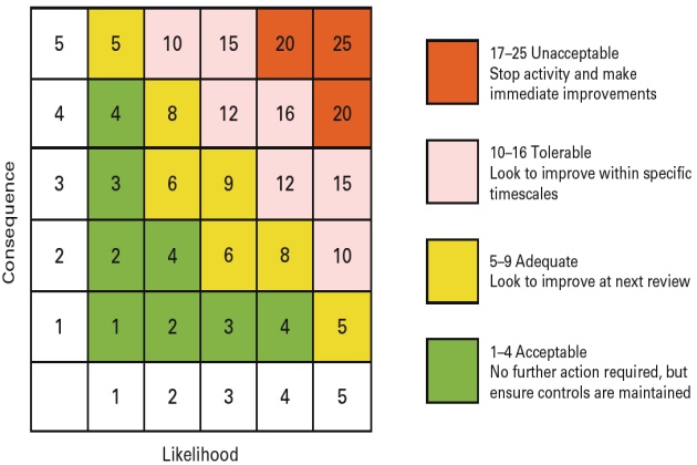
This form of semi-quantitative risk rating system gives an overall numerical value to the risk being evaluated. That numerical value can then be used to prioritize the actions required, as shown in the grading on the right of the matrix.
Semi-quantitative risk assessments also offer a degree of consistency. By using a matrix like this, trained risk assessment teams across the organization are more likely to develop a more consistent approach to risk rating.
Quantitative risk assessment
In the oil and gas industry, the hazards associated with complex processes and operations require a sophisticated approach in order to evaluate the risks involved. Quantitative risk assessment techniques provide the means to make a detailed assessment that will be based on quantitative considerations of event probabilities and consequences.
The quantitative risk assessments will involve using special quantitative tools and techniques in order to identify hazards, to give an estimate of the severity of the consequences and the likelihood of the hazards being realized. The quantitative risk assessments will result in the provision of numerical estimates of the risks, and these can then be evaluated when compared with known numerical risk criteria.
Historical data analysis
Historical data analysis is the basis for many quantitative risk assessments. Frequencies are simply calculated by combining accident experience and population exposure, typically measured in terms of installation-years:
- number of events number of installations x years of exposure.
One example of a source of historical data which can be used as the basis for quantitative risk assessments is the Worldwide Offshore Accident Databank (WOAD).
How risk management tools are applied in process safety risk identification and assessment, application in project phases from concept, design, start up, the concept of ALARP and the management of major incident risks
Introduction
When a project is in the design stage, some risks can be “designed out”, as can some of the hazards, using modelling as a tool. Unfortunately, the hydrocarbon inventory will always remain as a major hazard, as it’s the very reason the industry is there in the first place. Examples of modelling techniques are:
- HAZID (Hazard Identification Study);
- HAZOP (Hazard and Operability Study);
- FMECA (Failure Modes and Effective Critical Analysis)/FMEA (Failure Modes and Effects Analysis) We are now going to look at each of these modelling techniques in more detail.
HAZID (Hazard Identification Study)
A Hazard Identification Study (HAZID) is, as its name suggests, a tool for identifying hazards. It is normally a qualitative risk assessment and is judgement based. It is usually undertaken by a team of people who will be selected because of their particular knowledge, experience or expertise.
The reasons for identifying hazards are twofold, as follows:
- To compile a list of hazards which can then be evaluated using further risk assessment techniques. This may be described as “failure case selection”;
- To conduct a qualitative evaluation of how significant the hazards are and how to reduce the risks associated with them. This may be described as “hazard assessment”.
The following features are essential elements of a hazard identification study:
- The study should be creative and dynamic. This will allow a wide scope of hazards to be considered;
- The study should take a structured approach so as to be comprehensive in its coverage of relevant hazards;
- The study should embrace historical data and previous experiences so that lessons learned can be acted upon;
- The scope of the study should be clearly defined. This is to ensure that those who read the study fully understand which hazards have been included and which have been excluded.
Hazard checklists
These are an effective means of producing a comprehensive list of standard hazards which can be used for hazard identification studies at the concept and design stages of a project to consider a wide range of issues related to FAQ about Basic Facts, Safety and Security Clarifications of Liquefied Natural Gassafety. It is also used to confirm that good practice has been built into a project at the design stage.
The use of keywords as a prompt can be useful when considering hazards in a HAZID. Table 2 shows examples of keywords and some of their associated hazards. The list is not intended to be comprehensive.
The strengths of a hazard checklist are that:
- It is relatively cheap to produce and can be created by a single analyst;
- It can be used to help prevent the recurrence of previous incidents;
- It can be used for concept designs with a minimum of installation information;
- It can use the experience gained from previous risk assessments.
Its weaknesses are that:
- It may not be able to anticipate accidents which may occur in new designs;
- Using a generic checklist does not encourage new thinking about possible hazards, which can limit the understanding of the types of hazard specific to the installation.
In conclusion, a generic checklist is a useful tool for most risk assessments, although it is advisable to use it alongside other hazard identification study methods.
HAZOP (Hazard and Operability Study)
Hazard and operability studies are usually conducted at the design stage of a plant in general and the operating and safety control systems in particular. Consequently, they offer an opportunity to pre-empt hazards at a stage where they can be evaluated and dealt with before they become a reality.
A Hazard and Operability Study (HAZOP) is a tool which is used to systematically examine every part of a process or operation in order to find out how deviations from the normally intended operation of a process can happen, and if further control measures are required to prevent the hazards, which have evolved from the study, from happening. In order to do this, the HAZOP uses a complete description of the process, including Process and Instrumentation Diagrams (P&IDs) or their equivalent.
The hazard and operability study uses a qualitative assessment technique to ask “what if” questions to identify problems before the start of operations. Every part of the installation is systematically examined by a team which comprises experts with a wide range of skills and experience relevant to the installation. The costs of conducting the HAZOP and any recommended implementations will be more than offset by the savings in resources – from commissioning times to lives saved. The questions are set around guide words which are developed from method study techniques. This allows the questions asked to explore every possible way the operation could deviate from the normal intended operation of the process, and thus test its integrity.
The systematic approach of this technique is advantageous in failure case identification.
The hazard and operability study is useful in the communication between the design team and the operator(s) of the installation. It also provides opportunities for the provision of training for key production staff of new installations.
As we’ve mentioned, HAZOPs may be used at the design stage, but they can also be used when plant alterations or extensions are to be made or applied to an existing facility.
The HAZOP procedure involves selecting a line in the process, and one of the team, with the appropriate knowledge, describes the normal operating procedure or function of this line. Various scenarios, prompted by the guide word list, such as HIGH PRESSURE are then applied. Consideration is first given as to what could cause this particular deviation. Thereafter, the consequences or results of the deviation are discussed. The next step is for the team to consider how credible this particular scenario is, whether its effects are significant, and whether additional safeguards are required.
Let’s now look at an example of the logical sequence of steps in conducting a hazard and operability study.

Hazard and Operability Study (HAZOP) – process guide words
In our example we used HIGH PRESSURE as the deviation. The following are other examples of guide words used in a HAZOP analysis. This list is not meant to be exhaustive.
The effectiveness of a hazard and operability study will depend on:
- How the team is made up – the range of skills and experience of the individual members;
- The team leadership – the chairperson should ensure that the team is aware of, and follows, stringent procedures which systematically test the integrity of the design;
- How current the information is – the team should have the most up-to-date and accurate data available to them, including process and instrumentation diagrams (P&IDs);
- The team systematically examining the information to establish the cause and effects of any potential hazards resulting from deviations from the design.
Hazard and Operability Study (HAZOP) – team members
The HAZOP team should consist of a group of people who, between them, have expert knowledge in every area of the process plant and its operations. Typically they are a group of between five to eight people in the fields of management and engineering. They need to be aware of all of the details in the process and instrumentation diagrams (P&IDs) if it is a new process at the design stage but, if the plant is already in existence, then the team also needs to include process and maintenance staff to ensure that all aspects of the process plant and operations are considered. The leader of the team, the chairperson, should be fully au fait in hazard and operability study techniques in order for him/her to ensure that the team follows the procedure comprehensively and systematically.
An example of a HAZOP team that has been assembled to consider the design of a new chemical plant could comprise the following people:
- Chairperson – This should be a person who has not been directly involved with the design of the plant, but who has experience in hazard and operability studies. This is so he/she can work independently to ensure that all procedures are followed correctly. Although independent of the design team, the chairperson would benefit from having an understanding of the plant design;
- Design engineer – This is the person who has been involved with this particular project and will be available to provide information about details of the design;
- Process engineer – In this case, this will be a chemical engineer who will be the person responsible for developing the process and instrumentation diagrams (P&IDs) as well as the process flow diagram;
- Electrical engineer – The person responsible for developing the design of the electrical systems within the plant;
- Instrument engineer – This is the person who was concerned with the design and selection of the control systems for the plant;
- Operations manager – The operations manager will be the person in charge during the commissioning and operation phases of the plant.
The strengths of HAZOP are:
- HAZOP studies are well known and widely used so the advantages and disadvantages are well recognized;
- HAZOP studies use the knowledge and experience of operational staff within the team;
- HAZOP studies are used to systematically examine every part of the design, in order to identify every conceivable deviation;
- HAZOP studies can be used to identify possible technical faults as well as any human errors which may occur;
- HAZOP studies, whilst identifying existing safeguards, are also able to evolve and develop further controls or safeguards;
- The use of a team for HAZOP studies in offshore operations is advantageous in that it comprises of a wide range of disciplines from a variety of differing organizations.
Its weaknesses are:
- Its success depends on the effectiveness of the chairperson and the knowledge and experience of the team;
- It is best suited for use in identifying process hazards;
- for it to be used for other types of hazards it will need modifying;
- Procedural descriptions are needed, and these may not be available in sufficient depth of detail to involve all conceivable scenarios;
- The documentation required to record the study comprehensively can be extensive and overwhelming.
FMECA (Failure Modes and Effects and Criticality Analysis)
An FMECA (Failure Modes and Effects and Criticality Analysis) is a method of systematically identifying the failure modes of an electrical or mechanical system. One or two people examine each component of the system in turn and evaluate the effects and the degree of importance if that component should fail.
The examination uses a document that contains a systematic list of all of the components, and usually includes:
- The name of the component;
- The function of the component;
- The possible types of failure;
- The causes of each type of failure;
- How each failure is detected;
- The effects of each failure on the primary system;
- The effects of failure on other components;
- Necessary actions to prevent each failure or what actions are necessary to repair each failure;
- Degree of criticality.
The strengths of an FMECA are:
- It is a well-used and understood hazard analysis tool;
- It may only take one person to perform the analysis;
- It should identify all conceivable electrical and/or mechanical hazards;
- It identifies safety-critical equipment/components where a failure would be critical for the system.
Its weaknesses are:
- It’s dependent upon the experience and knowledge of the analyst;
- The analyst needs to develop a hierarchical system drawing before he/she can perform the analysis;
- It is limited to mechanical and electrical equipment and is not applicable to procedures or process equipment;
- Human errors and multiple failures are difficult aspects to cover;
- It is likely to produce a complex list of failures.
FMECAs, although useful for safety-critical mechanical and electrical equipment, should not be used in isolation. This is because human error is a contributing factor in many accidents and it is difficult for failure modes and effects and criticality analysis to identify this.
As Low As Reasonably Practicable (ALARP)
In this chapter, when we have been discussing the application of risk controls, we have mentioned on a number of occasions the phrase “as low as reasonably practicable”. We now need to understand just what this phrase means.
There is risk in every aspect of our lives – in everyday activities (e. g. crossing a busy road) as well as in our working lives (e. g. slips and trips at the office or more serious accidents with machinery or working with hazardous substances). What is necessary is to reduce those risks to an acceptable level; another way of putting it is to reduce the risk to “As Low As Reasonably Practicable” (ALARP).
What this means is that employers should adopt appropriate safety measures unless the cost (in terms of money, time or trouble) is grossly disproportionate to the risk reduction. Once all such measures have been adopted, the risks are said to be “as low as reasonably practicable”.
Read also: All you need to know about Process Safety Management in Liquefied Petroleum Gas Industry
Examples of the extremes might be that to spend £1 million on replacing chairs in the control room with ones with better lumbar support could be regarded as disproportionate. However, to spend £1 million on installing a fully protected escape route from the temporary refuge facility to the Crew Evaluation System CBT test online for seamans about Lifeboat Release Mechanism Harding FFlifeboats and helideck could be regarded as far more proportionate.
In the oil and gas industry, the risk of fire and explosion and their consequences rank highly, not only in financial terms, but also to human life and the environment. It is because of these potential consequences that what is regarded as “reasonable” in the oil and gas industry is at a much higher level than in most other industries. Consequently, more stringent control measures will need to be put in place to reduce the risk to a level which can be regarded as low as reasonably practicable.
Management of major incident risks
When it comes to managing the risks of a major incident, this should take a hierarchical approach. The recommended hierarchy is:
- Elimination and minimization of hazards (designing safety into process and systems);
- Prevention (the reduction of the likelihood of a major incident);
- Detection (the warning and alarm systems transmitted to the control area);
- Control (the limitation of the scale, the intensity and/ or the duration of an incident);
- Mitigation of consequences (the protection from effects of an incident).
Inherently safer design and measures to prevent and control major accident hazards warrant the highest priority. This is because they have the greater effect and, as such, offer dependability in reducing risk. The optimum point in time to identify and eliminate or reduce the risk of major hazards on a new installation is at the design stage. This is the stage at which all elements of the process and plant are examined and tested and where the risks are prioritized in order of significance. It is always best to prevent or eliminate risks by engineering design which will make the installation inherently safe, and then any residual risks can be controlled by the implementation of management and other controls. It is more difficult to eliminate or prevent risks on existing installations, although to comply with likely legislative requirements they should be reduced to As Low As Reasonably Practicable (ALARP).
The safety case/report of an installation should consider what the effects of fire and explosion would be on the integrity of the installation – especially offshore, i. e. there is the risk of the installation becoming unstable and unable to keep on station. There is also the risk to the environment from the effects that a release of toxic gas would have.
The lessons learned from investigations into previous incidents cannot be overstated when it comes to managing the risks associated with major incidents. An example of this is the report forthcoming from the Buncefield incident which occurred in December 2005. In this incident there was an explosion and the fires that followed it had a massive impact, not only on the plant, but also on the residents and business community locally and further afield. It was fortunate, however, that no lives were lost in this incident.
Although the recommendations which resulted from the subsequent enquiry into the incident were associated with how to respond to land-based incidents, some of the general principles can be applied to offshore facilities.
The principal recommendations were as follows:
- To review emergency arrangements to cover all reasonably foreseeable emergency situations which may result from credible major incidents. The word “credible” in this instance to be broadened so that some scenarios, which may previously have been regarded as unrealistic, should be considered;
- To ensure that guidance, which is related to existing emergency plans, is reviewed by an external, independent authority;
- To ensure training is given to all relevant staff in order that they become competent in the implementation of the emergency plan, should such a situation arise. They must also ensure that there is an adequate level of trained staff available at all times;
- To ensure that the control centre used for an emergency situation is appropriately sited and adequately protected should an emergency situation arise, as should any facilities required for the emergency response. If any changes are needed to achieve this recommendation then the safety case/ report should be updated to show the changes;
- To ensure all critical emergency response resources are identified and contingency plans exist in case any of them fail;
- To ensure that adequate arrangements with all external emergency services have been made so that, should an emergency situation arise, they are fully prepared to deal with it;
- To ensure that there is regular communication between the operator of the installation and any external agencies that may be affected by it. An example of this would be the coastguard, who may be affected by the activities of the operators of an offshore installation.
Industry related process safety standards, inherent safe and risk based design concepts, engineering codes and good practice
Industry related process standards
The oil and gas industry is a multi-national operation and is governed by both national and international health and safety regulations and codes of practice which are developed and enforced by government departments and other authorities throughout the world (e. g. the Occupational Safety and Health Administration (OSHA), the Health and Safety Executive (HSE), etc.). Governments and enforcing authorities tend to work in conjunction with the oil and gas industry in order to develop these codes of practice and legislation, which develop out of the specialized knowledge and experience which these industries have in managing their risks. Models of risk management which have developed over time are shared globally throughout the industry and minimum standards of health and safety are commonly accepted and adopted by the multinational companies.
The oil and gas industry has also set up a number of bodies which provide a forum for the exchange of ideas as well as a means of notification of hazards or the development of improved working practices.
Inherent safe and risk based design concepts
One of the main elements of developing inherently safe processes is to recognize that, by reducing the complexity of the plant at the design stage and simplifying the operation process, a significant reduction in the likelihood of accidents occurring can be achieved. This is because there is less equipment to malfunction and fewer opportunities for human error.
The design of a process which is as inherently safe as possible is the main goal of process designers. It is impossible to design out all risks, but process designers can use a hierarchical structure, with hazard avoidance being the priority, followed by the control of any risks remaining.
Control features, such as designing a system which can withstand the maximum likely pressure possible, are desirable elements where hazards cannot be designed out completely. However, where control is not possible, then mitigation by designing in means of reducing the magnitude of a hazard if it is realized is acceptable.
There are a number of principles for achieving an inherent safe design:
- Minimizing the amount of hazardous material present at any one time;
- Replacing hazardous materials with less hazardous materials;
- Moderating the effect a material or process might have (reduce temperature or pressure);
- Simplifying the design by designing out problems rather than adding features to deal with problems;
- Designing in tolerance levels to cope with faults or deviations;
- Limiting the effects of any adverse event, e. g. via bunds around storage tanks;
- Allowing for human error by designing in failsafe features such as valves which fail to a SHUT position.
Ultimately, five spheres were lost in the disaster even though emergency services were on scene. This was because they failed to cool adjacent tanks and the surrounding area and a domino effect was allowed to evolve.
Lessons learned
This particular incident raised a number of issues, including:
- The design of spheres (including insulated pipework and valves, insulation of tank supports);
- Procedures for draining water from spheres;
- The need for fully trained and competent operators to do the work;
- The need for emergency planning and procedures This illustrates the need for well-trained staff to do their work in accordance with set procedures in order to reduce the risk of a hazard being realized. Operators should also be trained to deal with abnormal situations, should they arise, so they can comprehend alternative solutions if others fail.
The concept of hazard realization
Introduction
Hazard realization is when a system of hazard controls breaks down or fails, which in turn causes a hazardous event to occur. The realization of a hazard can be catastrophic in the oil and gas industry, and a prime example would be a Boiling Liquid Expanding Vapour Explosion (BLEVE).
We mentioned before the 1966 Feyzin disaster in France. It’s worth looking in detail at what exactly happened in this incident.
Three operators were draining water from a sphere containing Liquefied Petroleum Gas (LPG). This was a routine procedure, but none of the operators undertaking the task on this occasion had any experience in performing the task. There was a written procedure which showed how to open the valves in a specific sequence, but this was not referred to by the operators. Consequently the valves were not opened in the right order (the closest one to the sphere was opened first) and an ice plug (hydrate) formed around the internal mechanism of the valve, making it inoperable.
LPG then began to flow from the drain valve, expanding and causing a huge vapour cloud. Being unable to close the valves, the operators fled the scene. The vapour cloud drifted over a nearby autoroute and ignited (possibly from a vehicle’s exhaust). The flames then tracked back to the leaking sphere and resulted in a jet fire which then spread to another LPG sphere. This caused the Boiling Liquid Expanding Vapour Explosion (BLEVE) and the sphere exploded. Other spheres collapsed as their support legs buckled because of the heat which caused them to also explode.
The concept of risk control using barrier models
Barrier modelling
A barrier is described as something which is placed between a person and a hazard to prevent that person from being harmed. For example, a barrier around a hole in the pavement made by workmen to repair pipes is provided to prevent people from falling into that hole. Another example is barrier cream, which is applied to protect hands from harmful substances such as cleaning fluids which would cause skin irritation.
Barriers can also be intangible things which protect people from harm, e. g. knowledge and training. An example of this would be learning how to use an industrial machine safely so as to protect the operator from injury.
Another type of barrier could be the use of Personal Protective Equipment (PPE), but there is no guarantee that this will be sufficient on its own to protect the wearer from harm. PPE can be breached in a number of ways, as the model in Figure 3 illustrates. The barrier is designed to protect the wearer from the hazard but, as illustrated, it can fail to do this in a number of ways. Knowing how these failures happen offers an opportunity to anticipate them and install control measures to minimize the risk of harm being done.

Let’s now look at what barriers we might put in place in order to reduce the potential exposure.
Control measures in place to mitigate potential exposure
As shown in Figure 4, the risk can be minimized by putting in several barriers. Although every barrier can be breached in a number of ways, each of them reduces the exposure to some extent.
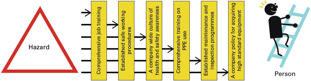
In order for the hazard to be realized it would be necessary for all of the barriers to be breached simultaneously.
Examples of good barriers are:
- Good design and specifications;
- Good processes and procedures;
- Robust Crew Evaluation Test online for seamans about Vessel Inspectioninspection and maintenance techniques;
- Adequately trained and competent personnel.
Use of modelling such as thermal radiation output, blast zones for risk identification
Introduction
There are a number of modelling tools available to help in identifying risks of fire and explosion.
The effect of heat on humans is based on a simple set of rules using kilowatts per square metre (kWm2). At 5 kWm2 escape from the effects of the heat can be expected. At 12.5 kWm2 death can be expected within minutes. At 37.5 kWm2 death is instantaneous.
The risks involved depend on the type of fire and its individual characteristics, so it is useful to look at all relevant types of fire and the modelling techniques associated with them in order to help in risk identification and subsequent risk reduction.
Pool fires
A pool fire is a fire burning above a horizontal and stable pool of vaporizing hydrocarbon fuel. If the fuel is not stable, it is known as a running fire. Figure 5 shows a typical pool fire.
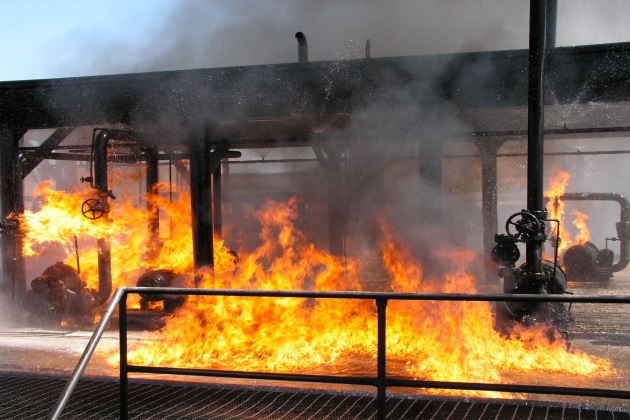
Pool fires present significant risks, to offshore installations in particular, which can quickly escalate into major incidents.
Modelling involves knowing the pattern of events when a pool fire takes place and being able to design in certain mitigating factors. For example, the following is a section of a Health and Safety Executive (HSE) information sheet, “Modelling of Pool Fires in Offshore Hazard Assessments Offshore – Information Sheet no. 9/2008”.
Liquid spills will expand on a surface until they achieve a certain critical thickness. For non-porous and relatively smooth surfaces, such as steel decks, a typical pool depth will be 1 mm for non-viscous liquids. On this basis, each square metre of pool will hold 1,000 cm3 of liquid. If the spill of escaping liquid is ignited, the rate of pool spread is no longer simply a function of rate of fuel input, but is now governed by the balance of fuel input versus fuel burn-off rate.
As the pool increases in area, the proportion of fuel burning off increases until it eventually matches the rate of input. At this time the pool should remain constant in size.
This is only one sample characteristic from the document, but it does demonstrate that knowing about this characteristic can be extremely useful at the design stage of certain components or processes.
Jet fires
A jet or spray fire is a flame which is being fed by hydrocarbons continuously being released with significant momentum in a particular direction. Figure 6 shows a jet fire emanating from a storage tank.
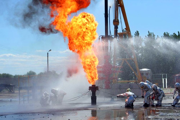
Like pool fires, jet fires present significant risks to offshore installations, where they can quickly escalate into major incidents. They are caused by releases of gaseous, flashing liquid and liquid inventories.
Jet fires develop rapidly, and the extreme heat they generate can result in structural failure if the flame impinges on critical members of the structure. This has important consequences for control and isolation strategies.
The properties of jet fires depend on:
- Fuel composition;
- Release conditions;
- Release rate;
- Release geometry;
- Wind direction and ambient conditions.
Industry practice in assessment of jet fire hazards
Assessment of the hazards of jet fires is made by analysing the length of the jet flame relative to the distances of equipment, buildings, people, etc. Consideration is given to the extent to which the affected area is impinged on, as well as the necessity for Passive Fire Protection (PFP) and emergency depressurization, as well as other options in order to mitigate the hazard.
Flash fires and fireballs
When a dense cloud of vapour is formed by the release of flammable gases or liquids and this meets a source of ignition, a Vapour Cloud Fire (VCF) may result. This is also known as a flash fire or fireball.

Vapour Cloud Fires (VCFs) are important for two reasons:
- There is the possibility that they may escalate and cause secondary fires elsewhere;
- It is highly probable that a steady fire will follow a VCF, i. e. a pool or jet fire or a combination of both.
Flash fires and fireball modelling
The duration, height and diameter, as well as the amount of uplift, are all characteristics of flash fires and fireballs which can be modelled using a formula based on the mass of fuel released.
Explosion hazard assessment
On any installation there is a possibility of a wide variety of explosions, including:
- Unconfined explosions (overpressure generated by the presence of obstacles);
- Confined explosions (overpressure generated by a combination of confinement and obstacles);
- External explosions (associated with confined, vented explosions);
- Internal explosions (e. g. within a flare stack);
- Physical explosions (e. g. a failing pressure vessel);
- Solid phase explosions (e. g. those which are associated with the use of well completion explosives);
- Mist explosions;
- Boiling Liquid Expanding Vapour Explosion (BLEVE).
On most installations, explosions are a significant component in the risk of topside fires. Data show that during the period 1992-1999 there were ten incidents involving explosions on UK installations. Most of the internal explosions were associated with flare systems or gas turbines.
Explosion hazard assessment modelling
Empirical models (knowledge acquired by means of observation or experimentation) employ a simplified version of the physics of an explosion and cannot deal with complex geometries. Consequently, their range of applicability is limited. However, they are useful for quickly calculating the order of magnitude of explosions, as well as for screening scenarios which then require further investigation with more sophisticated tools.
Phenomenological models (study of structures) are more complicated than empirical models. They are models which “fit”the experimental data and are used to represent the scenario geometry in simple terms, e. g. boxes connected by corridors. They also have a limited range of applicability, less so than empirical models, although they provide a lower level of uncertainty.
Computational Fluid Dynamics (CFD) models fall into two groups – simple models and advanced models. Advanced models provide a more complete description of the physical and chemical processes involved in explosions, including an improved representation of the geometry and accuracy of the numerical schemes.
Explosion consequence assessment modelling
This type of modelling looks at the consequences of explosions. For example, injury to people from an explosion can be as a direct consequence of the blast wave (e. g. rupture of the ear drum) or indirectly (e. g. from flying debris). Equipment and structures can be damaged by the effects of loading (affecting walls and large objects) or drag loading (affecting steelwork or pipework which is constructed of narrow crosssections) or a combination of both.
The Crew Evaluation Test online for seamans about Damage Prevention during shipping cargoextent of damage depends not only on the peak overpressure but also on the duration, impulse and rise time of the blast.
Revision questions for element 1 continued
Answer 1
- Step 1 – Identify the hazards.
- Step 2 – Decide who might be harmed and how.
- Step 3 – Evaluate the risks and decide on precautions.
- Step 4 – Record the findings and implement them.
- Step 5 – Review the assessment on a regular basis and update if necessary.
Answer 2
As low as reasonably practicable (ALARP) relates to reducing risk to a level regarded as low as reasonably possible. This is where an employer should adopt appropriate safety measures unless the cost (in terms of money, time or trouble) is grossly disproportionate to the risk reduction brought about by that particular safety measure or measures. Once all such measures have been adopted, the risks are said to be “as low as reasonably practicable”.
Answer 3
A Hazard and Operability Study (HAZOP) is a tool which is used to systematically examine every part of a process or operation in order to find out how deviations from the normally intended operation of a process can happen, and if further control measures are required to prevent the hazards, which have evolved from the study, from happening.
Answer 4
- Chairperson – This should be a person who has not been directly involved with the design of the plant, but who has experience in Hazard and Operability (HAZOP) studies.
- Design engineer – This will be the person who has been involved with this particular project and will be available to provide information about details of the design.
- Process engineer – This will be the person responsible for developing the process and instrumentation diagrams (P&IDs) as well as the process flow diagram.
- Electrical engineer – This will be the person responsible for developing the design of the electrical systems within the plant.
- Instrument engineer – This will be the person who was concerned with the design and selection of the control systems for the plant.
- Operations manager – This will be the person in charge during the commissioning and operation phases of the plant.
Answer 5
- Minimizing the amount of hazardous material present at any one time.
- Substituting hazardous materials with less hazardous materials.
- Moderating the effect a material or process might have (reduce temperature or pressure).
- Electrical engineer – This will be the person responsible for developing the design of the electrical systems within the plant.
- Simplifying the design by designing out problems rather than adding in features to deal with problems.
- Designing in tolerance levels to cope with faults or deviations.
- Limiting the effects of any adverse event.
- Allowing for human error by designing in failsafe features.