The article describes the structural design procedure of cylindrical and bilobe cargo tank, Type C as pressure vessels, according to the classification rules and supported by FEM analyses. This is illustrated for the case of 3 480, 6 500 and 8 350 cbm LPG carriers.
- Summary
- Nomenclature
- Introduction
- Stiffening rings
- Support reactions
- Ring forces
- Tank supports
- Swash bulkheads
- Remedy for misalignment of bilobe tank cylinders
- Remedy for misalignment of bilobe tank heads
- Strength analysis of cylindrical tank
- Strength analysis of spherical swash bulkhead
- Sloshing in long deck tank
- Conclusion
Summary
Some structural aspects as stress concentration in dome located in the area of stiffening ring, and two types of swash bulkheads, i. e. perforated hemisphere and flat grillage, are analysed. Misalignment problems, arising during tank construction, are pointed out:
- Y-joint of bilobe tanks in cylindrical area and area of tori spherical,
- and hemispherical heads are presented and valuable remedy solutions offered.
Also, the sloshing phenomenon in a long deck tank has been included.
Nomenclature
- C – coefficient.
- D – diameter.
- E – Young’s modulus.
- F – force.
- L – ship length.
- P – pressure amplitude.
- Q – shear force.
- Re – yield stress.
- Rm – tensile strength.
- T – period.
- V – velocity.
- W – weight.
- a – spring spacing.
- b – breadth.
- g – gravity constant.
- h – height.
- k – spring stiffness, correction factor.
- l – length.
- p – pressure.
- q – load.
- t – time.
- αβ – dimensionless acceleration.
- β – inclination angle.
- ρ – density.
- σam – allowable membrane stress.
- σas – allowable secondary stress.
- σat – allowable total stress.
- σe – equivalent stress.
- τ – shear stress.
Introduction
Increase in energy consumption results in the growth of gas sea-transport in liquefied state by means of special ships called Liquefied Gas Tankers. Two categories of these ships are distinguished, depending on the cargo type, i. e. Liquefied Natural Gas (LNG) and Liquefied Petroleum Gas (LPG) Carriers. Both types have unique construction features and differ considerably from other classes of ships.
The liquid petroleum gases are transported in one of the following conditions:
- fully refrigerated at slightly above atmospheric pressure,
- refrigerated, semi-pressurised below ambient temperature and over atmospheric pressure,
- fully pressurised at ambient temperature.
In all cases the cargo liquid state is near the boiling temperature at the given pressure. The boil-off petroleum gases Birth of the Reliquefaction, Design and Operation of the Reliquefaction LPG Plantare reliquefied and returned to the cargo tank.
Since the transportation of gas is hazardous due to many reasons of potential danger (fire, toxicity, corrosivity, reactivity, low temperature and high pressure), it is regulated by the International Maritime Organisation (IMO) within IGC Code. This IMO document has been accepted by the International Association of Classification Societies (IACS) and included in the Classification Rules.
For liquefied gas transportation different cargo tanks are used:
- integral tanks,
- membrane tanks,
- semi-membrane tanks,
- independent tanks.
In the Classification Rules the design features, i. e. tank shape and type of design analysis, and design pressure are used as criteria for tank definition, whereas the grade of refrigerating is of secondary significance. The design vapour pressure for the integral, membrane and semi-membrane tanks is limited to 0,25 bar. However, if the hull scantlings are increased accordingly the pressure may be increased up to 0,7 bar.
The independent cargo tanks are self-supported structures and do not participate in the ship’s strength. They are further subdivided into A, B and C types. The first two tank categories are usually constructed of plane surfaces (gravity tanks) and the design vapour pressure is to be less than 0,7 bar. Independent tanks, type C (MARVS < 0. 7 bar)Type C independent tanks are shell structures (also referred to as pressure vessels) meeting vessel criteria. They operate up to the design vapour pressure of 20 bar.
Fully refrigerated cargo tanks are free-standing prismatic type operating at temperatures down to -50 °C and limited pressure of 0,7 bar. These ships have cargo capacity from 5 000 m3 to 100 000 m3.
Refrigerated semi-pressurised tanks are usually of bilobe type. Their operation is limited by pressure of 7 bar and associated boil temperature depending on the kind of cargo. Cargo capacity of these ships is up to 15 000 m3.
Full-pressurised tanks are spherical, cylindrical or lobed supported by saddles. The maximum value of working pressure is 20 bar. The ships tend to be small with capacity of up to 4 000 m3.
This article deals with the structure design of the type C independent cargo tanks, also referred to as pressure vessels, as the most interesting task. The tank structure design requires realisation of the following:
- determination of tank shape and clearances,
- selection of high tensile steel and strength criteria, according to the list of cargoes that will be carried,
- determination of internal pressure that consists of the given design vapour pressure and liquid pressure. The latter is a result of combined gravity and acceleration effects due to ship motion in waves,
- calculation of acceleration components by means of guidance formulae based on ship particulars. Construction of acceleration ellipses in the ship transverse and longitudinal planes,
- calculation of shell thickness using the rather simple formulae for pressure vessels of various shell types,
- strength analysis of stiffening rings which transmit tank load (static + dynamic) to the tank support. The rings are loaded by circumferential forces due to the shear stress determined by the bi-dimensional shear flow theory based on the tank shear forces,
- buckling analysis of the tank shell and vacuum rings due to external pressure, i. e. difference between the maximum external pressure and the minimum internal pressure (maximum vacuum),
- strength analysis of swash bulkheads due to sloshing pressure,
- drawings of tank structure with welding details,
- list of material and nesting plans.
According to Classification Rules, the selection of tank material is based on the design pressure and temperature, and the list of transported products. In the next examples high tensile steel 12 Ni19 containing not more than 5 % nickel is used. It is produced in accordance with the standard EN 10028-4.
The material mechanical properties and the stress criteria are the following:
- Yield stress, Re = 390 N/mm2.
- Tensile strength, R = 540 N/mm2
- Allowable membrane stress, σam = 180 N/mm2
- Allowable total stress, σat = 308 N/mm2
- Allowable secondary stress, σas = 390 N/mm2
Stiffening rings
Support reactions
The stiffening rings are structural elements that transfer the tank static and dynamic load to the ship structure over the saddle supports. Dimensioning of the rings is a rather complex task since it requires FEM analysis.
The support reaction consists of a part of the tank and cargo weight, and dynamic load that depends on acceleration. It may be written in the form:
where:
- C is reaction coefficient as a percentage of weight transferred to the support,
- α β is dimensionless acceleration including gravity,
- W is total tank weight.
The support acceleration α β is determined for the ship in upright position and the biased ship for 30°.
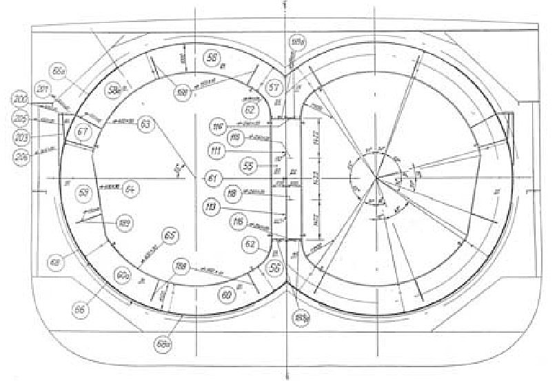
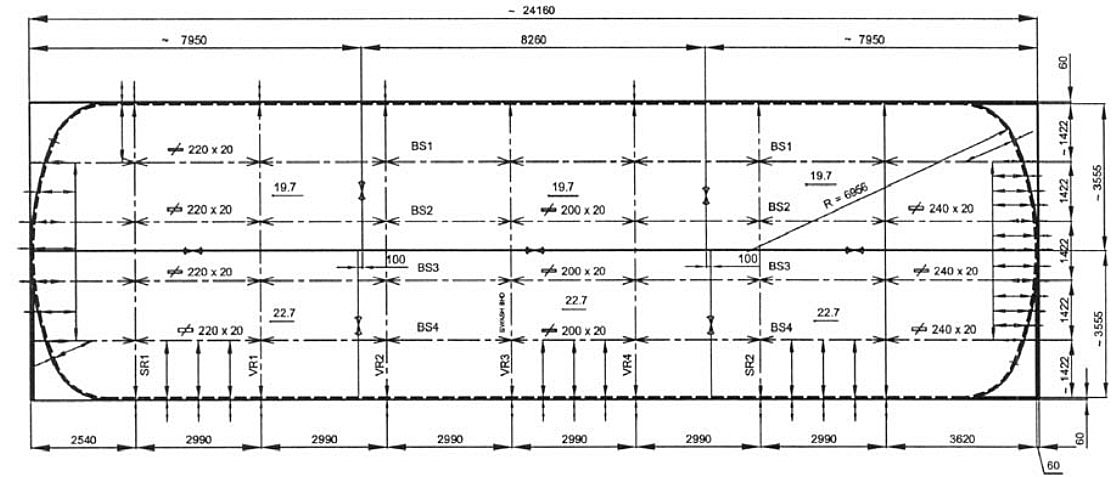
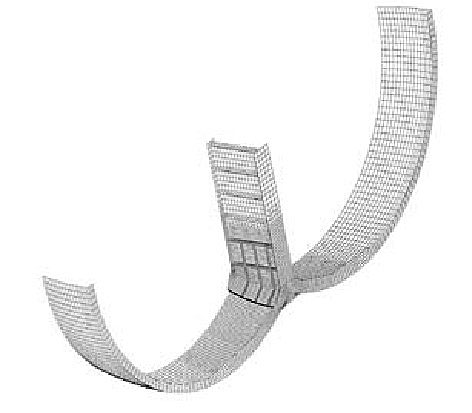
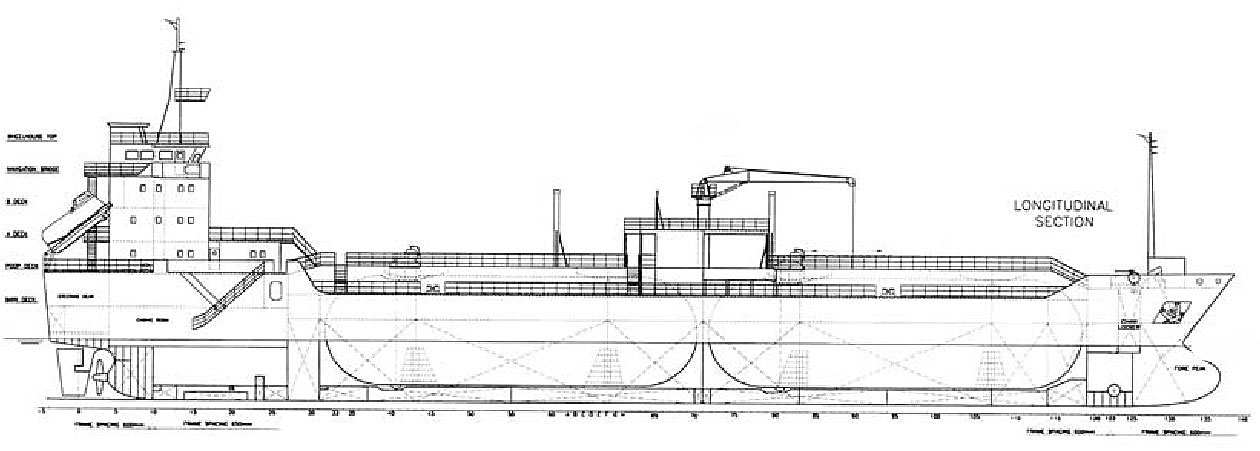
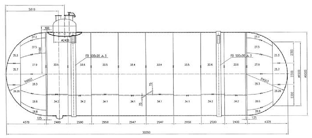
The 8 350 m3 LPG with three bilobe tanks built in the GL class is considered, Figures 1 and 2.
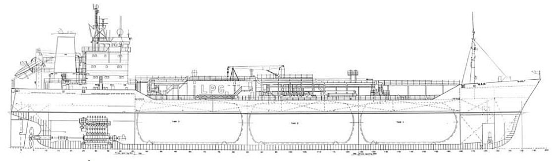
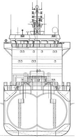
The cylinder diameter is 9 500 mm and the distance between cylinders is 6 300 mm. The design vapour pressure is 4,5 bar and the working temperature -104 °C + 45 °C. The reaction forces are determined for the heaviest cargo, i. e. vinyl chloride monomer, and are listed in Table 1.
The stiffening ring is exposed to the action of circumferential shear load due to tank bending between two supports. According to the Classification Rules the ring strength has to be considered for the ship in upright and biased positions.
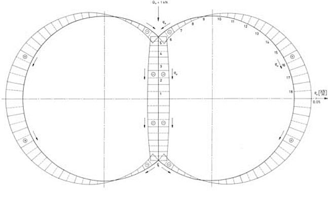
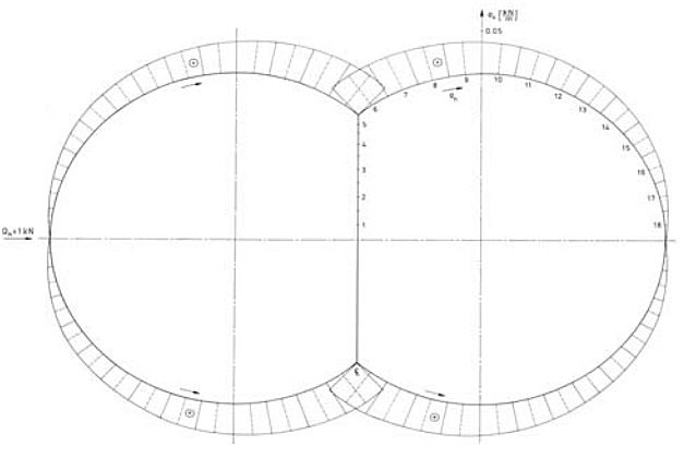
Shear load for the bilobe tank is determined for both vertical and horizontal tank shear force of the unit value. The calculation is performed by the in-house program STIFF, based on the theory of thin-walled girders, Figures 3 and 4.
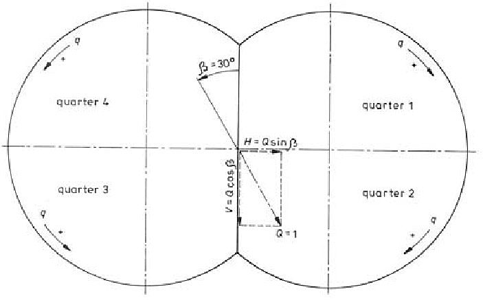
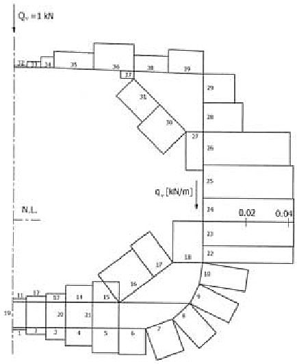
The resulting shear load for the quarters of the biased tank is obtained as follows, Figure 5.
Equation 2:
- quarters 1 and 3: q = qv cosβ + qh sinβ,
- quarters 2 and 4: q = qv cosβ – qh sinβ,
where β is the inclination angle. The final shear flow distribution for biased tank is shown in Figure 6.
Ring forces
The ring sectional forces due to the relative circumferential shear load are determined by the finite element method, using the software package SESAM. The model cross-section includes the assumed T-profile of the ring and the effective breadth of the tank shell. The same properties are assumed for the double side girder of the longitudinal bulkhead of the bilobe tank in the first step of the analysis.
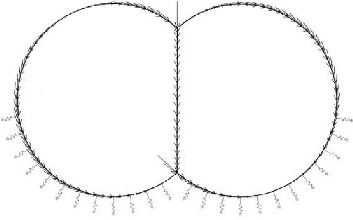
The FEM model consists of beam elements and it is placed on elastic springs that simulate the behaviour of the wood layer on the tank saddle support, Figure 6. The springs are distributed on each tank side within the central angle -30° to 80° of the saddle foundation, and they are directed radially. The spring stiffness yields:
where:
- E – Young’s modulus of wood,
- a – arc distance between springs,
- b – wood breadth,
- h – wood thickness.
In the considered case:
- a = 0,829 m,
- b = 0,25 m,
- h = 0,2 m,
and for the wood material known under the commercial name Lignostone H II/2/30-E5, Rochling Plastics USA, E = 1,655·107 kPa.
The calculation is performed for the tank in the upright and biased positions. In the former case all springs are pressed and active, while in the latter case some peripheral springs cause tensile force and are therefore excluded from the analysis.
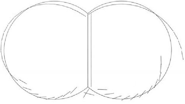
The obtained results, i. e. the ring deformation, the normal force, the shear force and the bending moment for the biased tank as a worse case are shown in Figures 7, 8, 9 and 10.
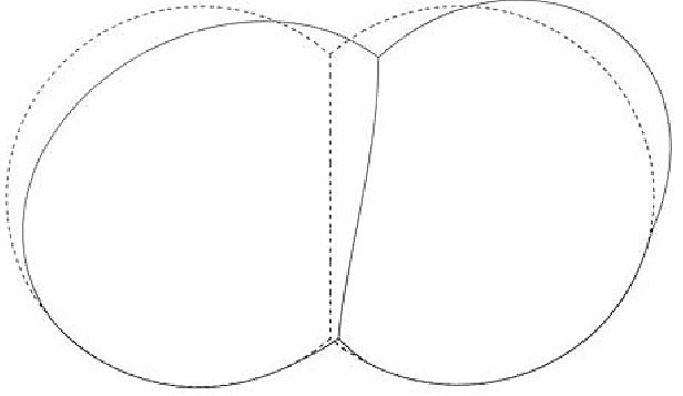
The ring is mainly deformed out of the saddle. The normal force is high at the bottom. The shear force reaches the maximum value at the ends of the saddle. The bending moment takes the maximum value at the end of the saddle in the lower lobe of the biased tank.

The actual sectional forces for each stiffening ring are obtained by multiplying their relative values calculated for the unit tank shear force with the corresponding value of the support reaction, Table 1.
The stresses caused by the actual sectional forces are calculated at five positions of the ring cross-section in both Gaussian points of each beam element of the ring FEM model.
The stress positions are chosen in the symmetry line of the cross-section, at the level of neutral axis, at the ends of the web and at the outer side of the flange and tank shell. Furthermore, the equivalent stresses at the same positions and points are determined using the von Mises formula.
where:
- σx and σy are normal stresses in the x and y direction respectively,
- τxy is shear stress in the xy plane,
- σn and σb are normal stresses due to the axial force and the bending moment respectively.
The final dimensions of the stiffening rings at different cross sections are determined by varying the initial scantlings until meeting the stress criteria. Based on the difference between equivalent and allowable stresses, the flange and web thickness and the web height are changed. The web height of each stiffening ring at the end of the saddle support is increased due to high values of the sectional forces in the case of the tank biased for 30°, Figure 11.
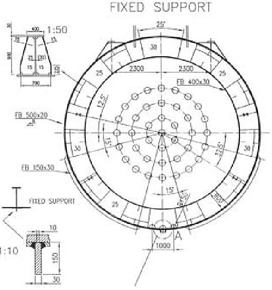
Tank supports
The cargo tank is placed on two saddle supports covered by wood layer, Figure 12.

One support is fixed, while the other is free to move in axial direction, Figure 13.
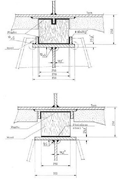
At the upper part of the stiffening rings the anti floating supports are constructed with a wood layer too, Figure 14.

The strength of the tank support may be checked by imposing the tank total load (static + dynamic) to the FEM model of support surrounding structure. However, more reliable results are achieved if the tank stiffening ring and ship hold structure is taken into modelling since in that case the interaction between the tank and the ship structure is ensured.
The strength calculation of the stiffening ring and the web frame is performed by the finite element method. The complete ship cross-section is modelled as a 2D problem, Figure 15.

The web frame model includes a strip structure between two-frame spacing. The effective breadth of the double bottom plating, shell and deck with the corresponding stiffeners are represented by the beam elements. The stiffening ring is a T-profile with effective breadth of the tank shell. It is modelled by beam elements in the area of lobe arches and double side girder at the longitudinal bulkhead.
The stiffening ring and the web frame models are connected by the radial bars, simulating in such a way the behaviour of the wood layer, Figure 15. Furthermore, the web frame model is placed on the elastic springs which transfer the influence of longitudinal girders in the double bottom and those of side shells and deck. The spring stiffness is determined assuming that the girders are clamped at the transverse bulkheads.
The strength calculation is performed for the upright and biased ship. The relevant shear load of the stiffening ring is imposed to the FEM model according to Stiffering rings, Figures 3 and 4. In the same way the web frame is loaded by the corresponding shear flow, Figures 16 and 17.

The model deformation is shown in Figure 18, while von Mises stress distribution in the web frame is presented in Figure 19.
The stresses are higher in case of biased ship, with maximum value at the end of the lower support. Maximum stress value is obtained at the side end of the saddle support.
Diagrams of the stiffening ring normal force, shear force and bending moment are similar to those shown in Figures 8, 9 and 10 respectively, obtained for the uncoupled problem. Maximum values of sectional forces for both analyses are compared in Table 2. Generally, the values of uncoupled analysis are higher than those of coupled stiffening ring and web frame analysis.
2D FEM model of the web frame is primarily constructed to ensure proper elastic support of the cargo tank in simplified strength analysis. Therefore, in order to check the web frame scantlings, it is necessary to perform a more sophisticated strength analysis of the middle part of the ship structure between two transverse bulkheads by a 3D model.
Swash bulkheads
The number of necessary swash bulkheads in a tank is chosen in such a way that resonance of the fluid sloshing with the ship pitching is avoided. Several formulae for evaluation of the pitching period are available in the Classification Rules. According to DnV and LR recommendation the natural period of fluid in longitudinal direction in cylindrical and bilobe tanks may be presented in the following form:
where:
is natural period for a tank of general shape. Furthermore, according to GL:
is correction factor for cylindrical and bilobe tanks. In the above formulae l is the length of liquid free surface, h is the filling height, D is the tank diameter and g is the gravity constant.
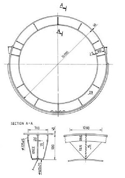
The swash bulkhead is designed as a perforated plate with grillage stiffening, Figure 20.
It has to withstand sloshing pressure, which according to the GL recommendation is given by the simple formula:
where:
- L is the ship length,
- l is the length of liquid free surface,
- ρ is cargo density.
The scantlings of the bulkhead girders are determined in an ordinary way and assuming that they are simply supported at the ends.
The swash bulkhead is attached to the vacuum ring and the vertical girder of the longitudinal bulkhead by elastic springs. They are usually constructed of Ω–type, Figure 21.
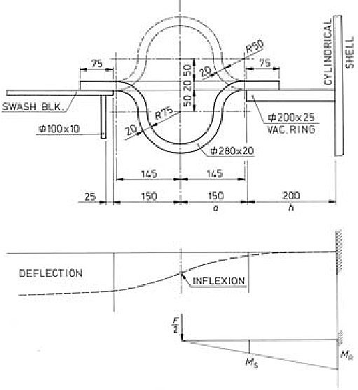
The strength of elastic springs is checked considering one half of the spring as a cantilever clamped at the vacuum ring. Due to forming the material to small radius during production, the fatigue life of the springs is reduced. As a result, after some years in service the Ω–springs are prone to crack. Therefore, it is preferable to use the elastic springs of U–type, Figure 22.
Remedy for misalignment of bilobe tank cylinders
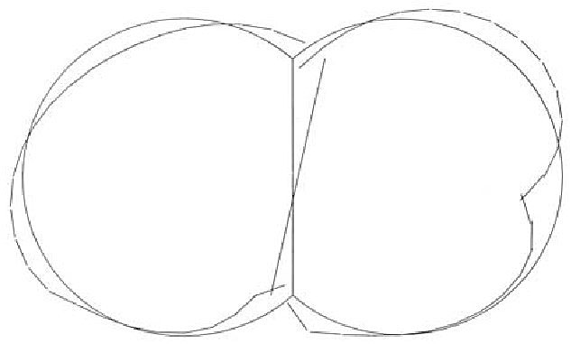
Bilobe tanks are shell structures and their fabrication is rather complex due to the curved surface and relatively thick walls. They are constructed with different success of geometrical perfection. Beside the residual stress due to welding, misalignment also causes stress concentration and it must be controlled. An especially difficult problem occurs in case of misalignment in Y-joint of the cylindrical shells and longitudinal bulkhead of bilobe cargo tank as illustrated in the following.
Bilobe tanks are designed as pressure vessels based on the membrane theory. However, even in an ideally performed Y-joint, the stress concentration with factor of ca. 1.3 occurs. In case of eccentricity of the tank shells at the Y-joint a bending moment is generated and the problem of stress concentration is more pronounced, Figure 23.
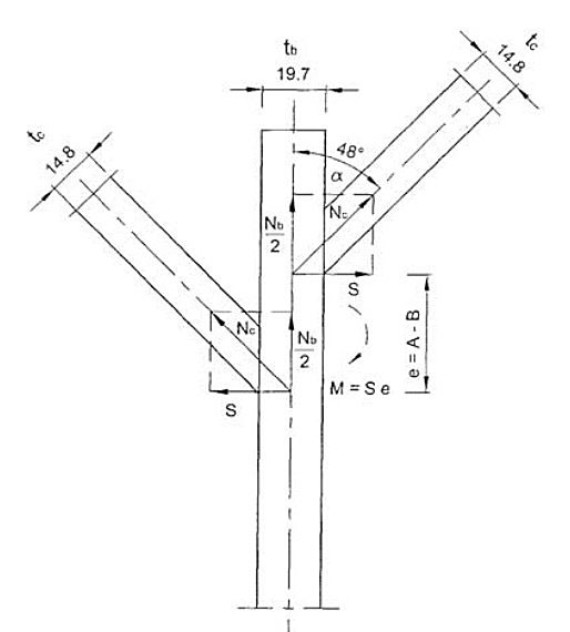
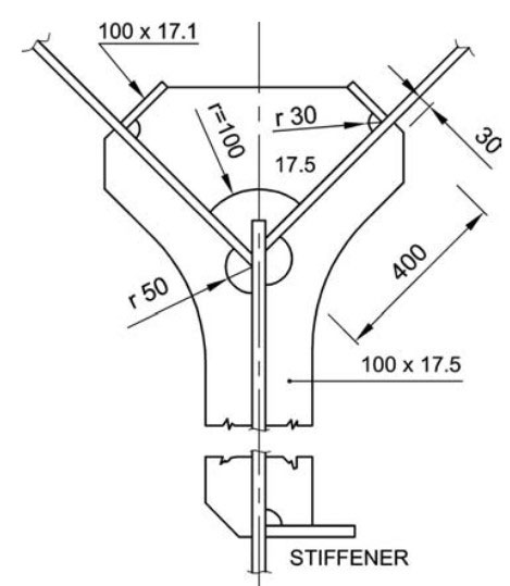
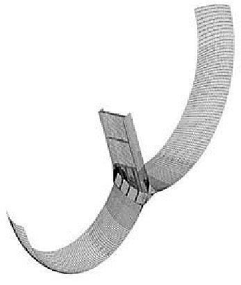
In the considered case the thickness of the cylindrical shell at the upper and lower Y-joint is 14,8 and 17,1 mm respectively, while the shell eccentricity varies within ±30 mm that results in extremely high stresses. In order to remedy misalignment without damaging the structure and provide easy access to all welds, a set of reinforcements consisting of knees and bars as shown in Figure 24 is recommended. The reinforcements are placed on both outer and inner side of the tank shell compensating in such a way for the bending moment without disturbance of the membrane stress state in the shell.
Strength analysis of the perfect, imperfect and reinforced structure is performed by the finite element method. For this purpose, one half of the tank segment between two vacuum rings is modelled. The value of eccentricity and the number of reinforcements are varied, Figure 25, and the maximum value of the total von Mises stress, σt, as function of these two variables, is shown in Figure 26.
Also, the allowable secondary stress, σas, is included in the diagram. Finally, an acceptable stepwise stress diagram is drawn for the practical use.
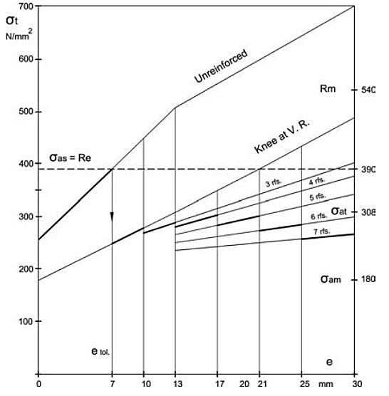
According to the stepwise diagram, the Y-joint of the cylindrical shells in Tank No. 3 is reinforced by adequate set of knees and bars depending on the measured eccentricity. A similar diagram is constructed and used for the reinforcement of the tank heads assuming analogical situation as in the case of cylindrical part of the tank. The position and the number of necessary reinforcements is shown in Figure 27.
After the tank has been completed it was submitted to the hydraulic test in accordance with the Classification Rules. The test pressure of 6,75 bar, i. e. 50 % higher than the design pressure was reached and off-loaded in 6 steps. The holding time of the maximum pressure was 2 hours. The hydraulic test was performed successfully without any problem, and no plastic deformation was registered.
Remedy for misalignment of bilobe tank heads
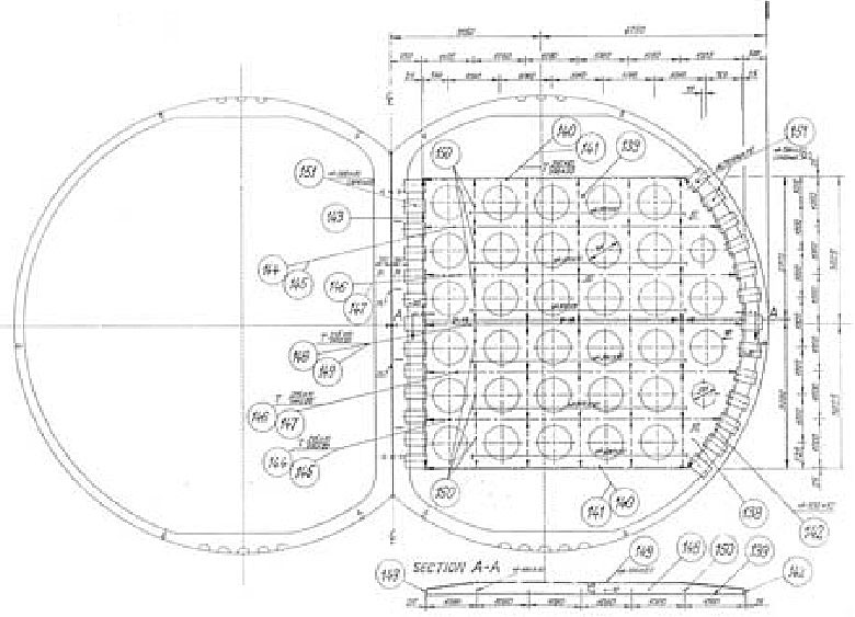
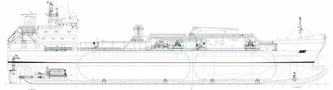
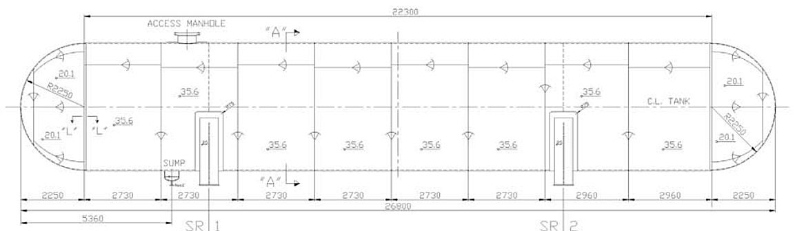
A 6 500 m3 LPG carrier with fore cylindrical tank and aft bilobe tank is considered, Figure 28. The cylinder diameter is 9 500 mm and the nominal pressure 4,5 bar. During the bilobe tank fabrication, a misalignment of the Y-joint in the fore tori spherical dished head and aft hemispherical head is detected. The thickness of the torus and sphere are 26 mm and 15,9 mm respectively, and the average value of intolerable eccentricity in the area of their connection is 26,2 mm. Thickness of the hemispherical shells is 11,1 mm and average intolerable eccentricity in the aft head reaches value of 31,4 mm.
The above problems are solved by reinforcing the tank heads with sets of bars and knees. FEM model of reinforced toroidal shell is shown in Figure 29.
It is fixed at the base and loaded by the total pressure of 7,21 bar, consisting of design and liquid pressures 5,41 and 1,8 bar respectively. One model cross-section end is fixed and the corresponding membrane force is imposed on the other. Maximum membrane and total stresses read 320 and 330 N/mm2 respectively, that is below the permissible value of 390 N/mm2 for the used material. The total stress distribution is illustrated in Figure 30.

In similar way the hemispherical segment of the aft head is reinforced, which can be seen in the FEM model, Figure 31.
The same boundary conditions and pressure load are imposed on the model as in the case of the fore head model. Maximum membrane and total stresses are 180 and 254 N/mm2 respectively, which is below the permissible value. The total stress distribution is shown in Figure 32.

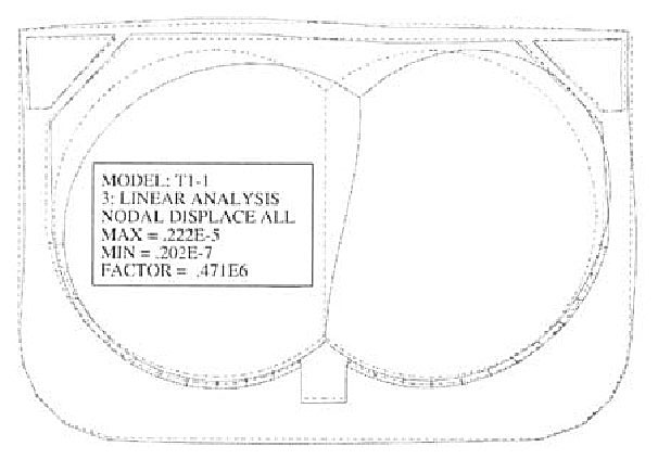
Strength analysis of cylindrical tank
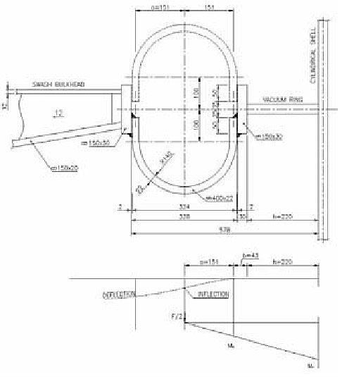
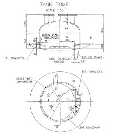
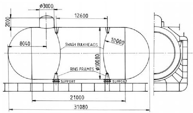
A 3 480 m3 LPG carrier, equipped with two fully pressurized cylindrical tanks with hemispherical heads, is taken into consideration, Figure 33. The tank diameter is 9 000 mm and the design pressure is 18 bar. Relatively thick tank shell ensures its stability and therefore the vacuum rings are not used. Thus, the swash bulkheads are fixed to the stiffening rings.
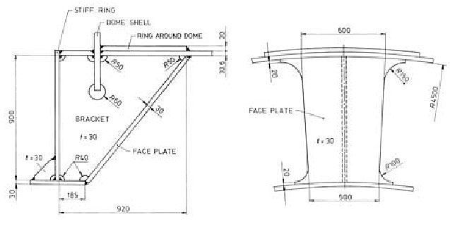
Two problems in the tank design occur, namely, insufficient torsional rigidity of the stiffening rings to transfer load of the hemispherical swash bulkheads, and location of the tank dome over the stiffening ring as a result of some operational requirements, Figure 34.
In the above circumstances it was necessary to reinforce the stiffening ring and dome. This is done by the so called cassettes and some knees, as can be seen in Figures 35 and 36.
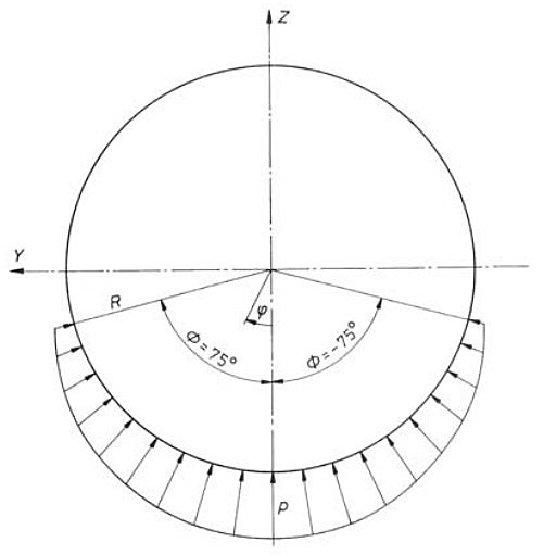
The FEM analysis of the tank aft part is performed for the ship in upright and biased position of 30°. In the former case the total (design + liquid) pressure of 2 000 kN/m2, and sloshing pressure according to Remedy for misalignment of bilobe tank cylinders of 36,75 kN/m2 are taken into account. For the biased tank only design pressure is imposed. The support reaction pressure for upright ship is assumed in harmonic form, Figure 37.
where pressure amplitude P0 takes the value of 1 936 kN/m2.
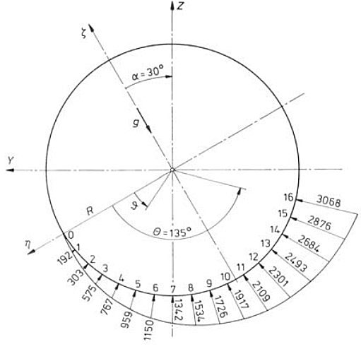
For the biased ship, linear function of support pressure is used, Figure 38.
Maximum values of von Mises stress in the tank structural elements for upright ship and sloshing pressure of two opposite directions are listed in Tables 3 and 4 respectively.
The stresses are below the allowable values except for the total stress at the top of the stiffening ring, and the membrane stress in the sphere at its joint with the cylinder.
The deformation of the biased tank is shown in Figure 39, where suspension of shell deflection by stiffening ring is evident.
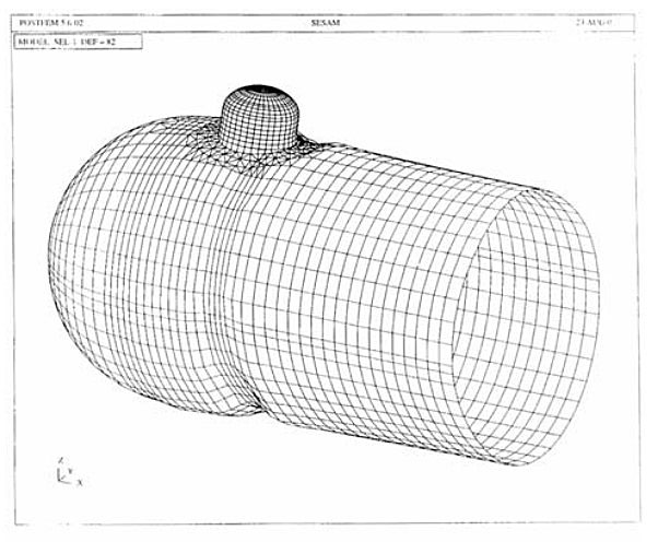
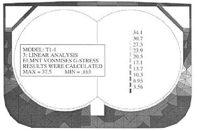
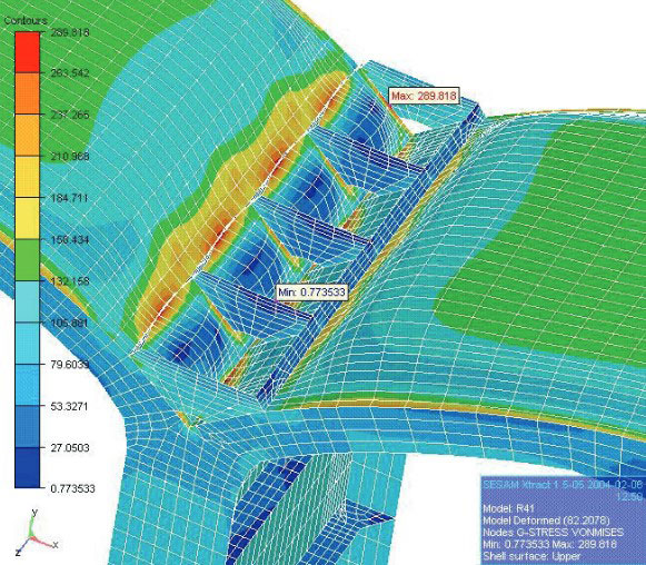
Membrane von Mises stress distribution is illustrated in the tank cylinder and dome cylinder, Figures 40 and 41 respectively.
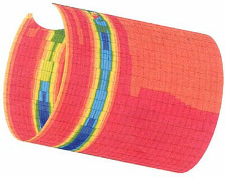
Maximum stress values in the structural elements are presented in Table 5.
Stress criteria are not satisfied in the same two elements as in the case of the upright ship. The first situation is tolerated since the total stress criterion is met at the hemisphere boundary. The second problem of high total stress at the top of the stiffening ring flange is overcome by inserting additional knees as shown in Figure 42.
Strength analysis of spherical swash bulkhead
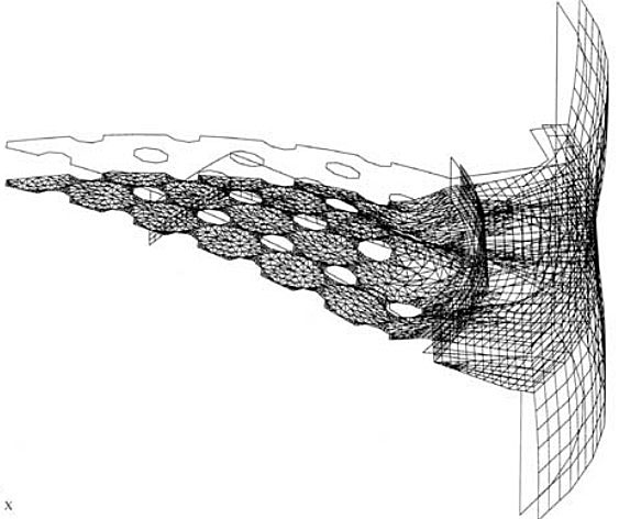
Sometimes swash bulkheads are designed as perforated spherical segments and fixed to the stiffening rings, Figures 43, 44 and 45. The stiffening ring is reinforced by a set of knees in order to take over the sloshing load from the swash bulkhead.

Since the swash bulkhead is a membrane, stress concentration occurs in its joint with the stiffening ring. The problem is investigated by FEM analysis. One eighth of swash bulkhead and stiffening ring with an effective part of cylindrical shell is modelled, making use of quadruple symmetry. Design pressure is imposed to the cylindrical shell pd = 1 988 kN/m2, and the sloshing pressure to the bulkhead ps = 41,31 kN/m2 is taken twice into account in opposite directions.
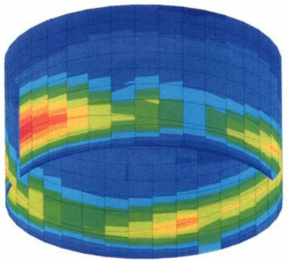
Model deformation (like a lace) is shown in Figure 46, while the total von Mises stress distribution can be seen in Figure 47.
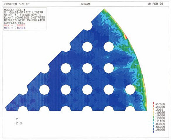
Stress concentration in circular boundary is evident. Maximum von Mises stresses in structural elements are listed in Table 6. Stress criteria for the used material are satisfied all over the structure.
Sloshing in long deck tank
A long deck tank, D/L = 4,5/26,8 m, on a 82 000 m3 LPG carrier is considered, (L×B×H = 215×36,6×22 m). The design pressure is 18 bar and tank structure is quite strong to withstand the sloshing pressure. Thus, the swash bulkheads are not necessary from the sloshing pressure reduction viewpoint. However, since the tank is relatively long it is preferable to avoid liquid resonance with ship motion.
Read also: Gas Tank Environmental Control
The configuration of the deck tank is shown in Figure 48. Liquid natural period is calculated in Table 7 for different number of swash bulkheads and filling level h/D.
For natural pitching period DnV formula, which gives lower value comparing to other classification rules formulae is used:
where:
- L – ship length, m.
- V – ship service speed, knots.
- Cv – speed reduction coefficient for heavy sea.
In the considered case Tp = 7,71s. Concerning resonance avoiding criterion, \( \style{font-size:22px}T_\style{font-size:22px}x^\style{font-size:22px}\ast\style{font-size:22px}\leq\style{font-size:22px}0\style{font-size:22px},\style{font-size:22px}8{\style{font-size:22px}T}_\style{font-size:22px}p \) is used, i. e. \( \style{font-size:22px}T_\style{font-size:22px}x^\style{font-size:22px}\ast\style{font-size:22px}\leq\style{font-size:22px}6\style{font-size:22px},\style{font-size:22px}{17}\style{font-size:22px}s\style{font-size:22px}. \)
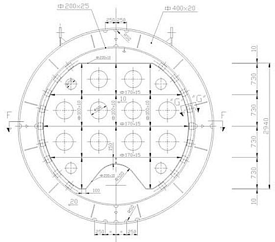
It is obvious that according to the data for \( \style{font-size:22px}{T_x^\ast} \) in Table 7, by two swash bulkheads, resonance of the above 50 % filled tank is avoided. Swash bulkheads of grillage type are located at the stiffening rings, Figure 49.
Dynamic pressure according to DnV rules:
takes the value of 54,09 kN/m2 in case of no swash bulkheads, and 25,43 if two bulkheads are included.
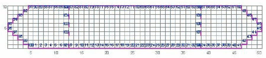
Dynamic pressure is also calculated by LR software. 2D model of the longitudinal tank section is used with resolution of 50×10 cells. Both tanks without and with two swash bulkheads are considered. In the former case there are 100 boundary cells, while in the latter 5 cells for each swash bulkhead are added, Figure 50. The obtained results are illustrated for the case of 50 % tank filling as the worst case.
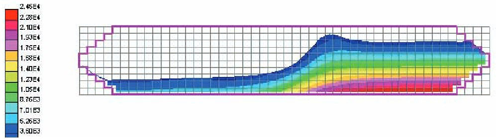
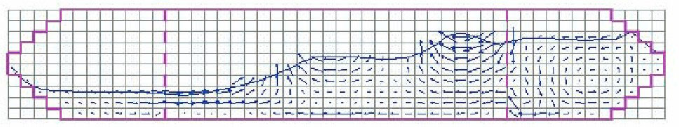
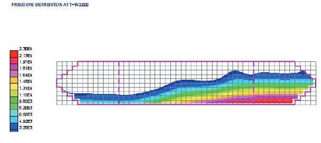
For the tank without swash bulkheads the velocity vectors and pressure field are shown in Figures 51 and 52 at the time point t = 160s. Hydraulic jump phenomenon is noticed in Figure 51.

filling, t = 160s
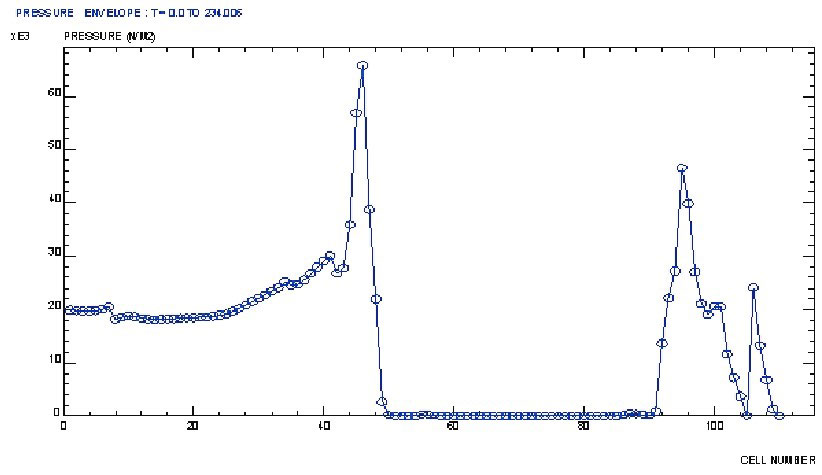
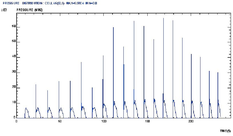
Pressure envelope along the boundary cells in the period of T = 234s, is shown in Figure 53.
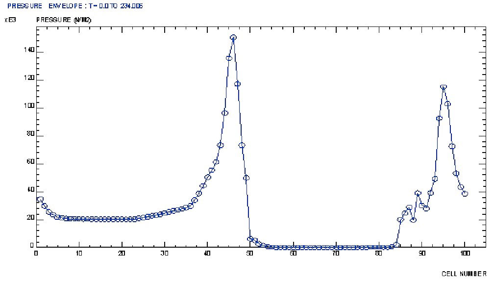
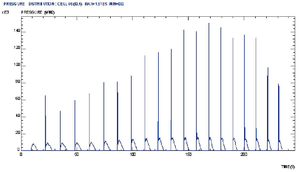
Maximum value of 150 kN/m2 is achieved at the fore head. Pressure time variation is of impulsive nature, Figure 54.
The influence of the swash bulkheads on the velocity vectors can be seen in Figure 55.
The swash bulkheads deduce the stream field to each tank compartment. The corresponding pressure field in t = 160s is shown in Figure 56.
In this way maximum pressure is reduced to 65 kN/m2, Figures 57 and 58.
By comparing the calculated and rule maximum sloshing pressure for the case without and with swash bulkheads, Table 8, we see that the latter are ca. 37 % of the former.
The reason is that the pressure impulses last for a very short time and most of the structures can withstand such a dynamic load due to their inertia. Thus, the structure behaviour is of relieving nature. Furthermore, the swash bulkheads reduce the maximum calculated pressure to the amount of 43 %, which effect is quite well taken into account in the rules.
Conclusion
Liquefied Gas Carriers are special and sophisticated vessels, which differ considerably from other classes of ships. The design and construction of their cargo tanks require special attention due to high pressure and low temperature. Since the transportation of liquefied gases is hazardous due to many reasons of potential danger, it is regulated by the International Maritime Organisation and the IMO code is implemented in the Classification Rules.
This article considers some typical problems which arise during C type tank design and construction, such as the strength and scantlings of stiffening rings, tank supports, swash bulkheads, remedy for misalignment in shell joints and sloshing in long tank. The stress concentration in the joints of structural elements of a perfect and imperfect structure is prerogative for fatigue analysis. The analysed problems an d application of the recommended solution, which have been checked in practice, may contribute to rational tank design and construction as well as to improvement of ship safety.