Reliquefaction plant were traditionally of the cascade type, using the cargo gas as the working fluid in the low pressure stage of the cascade and refrigerant R-22 in the high pressure stage. Over the last ten years this design has fallen out of favour and the simpler reliquefaction cycle, using cargo gas in a single circuit, has been in the ascendance. However, interest is again being shown in the cascade design. One reason for this move back to the traditional design is the ability of this system to allow an increased number of different cargoes to be carried.
- Summary
- Introduction
- History of LPG carriage and the birth of reliquefaction
- Design parameters
- Ship types
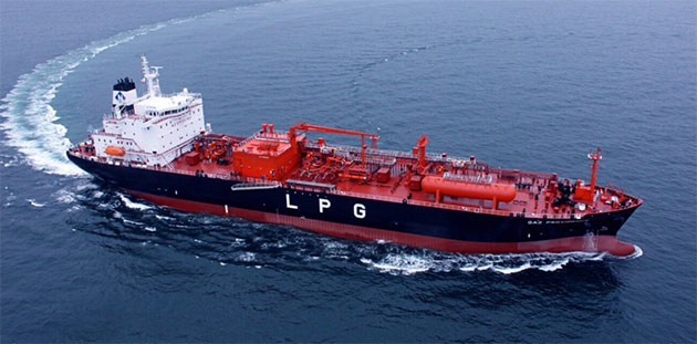
- LPG Cargoes
- Reliquefaction plant design development
- Reliquefaction plant
- Background
- Simple direct reliquefaction system
- Traditional cascade reliquefaction system
- Modern direct system
- Single verses multi-stage direct system
- Sizing the reliquefaction plant
- Indirect refrigeration systems
- Future options
- Different cargo requirements
- Butadiene
- Vinyl chloride monomer (VCM)
- Ammonia
- Isoprene
- Methyl acetylene/propadiene mixtures
- Propylene oxide
- Ethylene oxide/propylene oxide mixtures
- Methanol injection
- Inhibited cargoes
- Equipment
- Cargo compressors
- Refrigeration compressors
- Heat exchangers
- Purger
- Suction separator (knock-out pot)
- Other options – LPG as a fuel
- Concluding remarks
Summary
Each Liquefied Petroleum Gas (LPG) cargo has different storage and reliquefaction requirements. Whilst the heat ingress into the cargo tanks is dependent on the temperature of the cargo, the required duty of the reliquefaction plant, in order to maintain the temperature and pressure in the cargo tanks, differs for each cargo. The effect on the reliquefaction plant, of power consumption, required swept volume, compression ratio and condensing capacity, all need to be established to allow the plant to be operated at optimum efficiency.
This presentation summarizes the technical feasibility of each design of reliquefaction plant with each type of system being discussed. This will include the various operational modes of the reliquefaction plant depending on the cargo carried. Finally, the background and the methods of approval for the reliquefaction plant, the International Code for the Construction and Equipment for Ships Carrying Liquefied Gases in Bulk (IGC Code) requirements and the specific Lloyd’s Register Rules governing the design manufacture and installation of the reliquefaction plant will be examined.
Introduction
Liquefied Petroleum Gases (LPGs) are by-products of both oil and LNG gas fields. LPGs are also produced during the processing of crude oil. They do not naturally occur in independent gas fields. Historically, LPG consists of:
- propane,
- butanes,
- butylene’s,
- propylene.
However, there are number of other liquefied gases which are being carried by “LPG” carriers. The physical properties of the most commonly transported LPG gases are given in Table No. 2.
Over the last four years there has been great interest in reliquefaction. This interest is mainly due to the development and instigation of the commercial carriage of Liquefied Natural Gas (LNG) using reliquefaction instead of the boil-off gas being burnt in the ship’s main propulsion boilers. While the reliquefaction of LPG is relatively simple, with comparatively moderate energy consumption, the reliquefaction of LNG takes a considerable amount of energy and about 10 – 13 % of the LNG’s boil-off gases energy is used to reliquefy it.
The reliquefaction of LPG has evolved with both direct and indirect, cascade and multi-stage systems being used at some point. The design of ship – Type A or semi-pressurised Type C – also directly affects the design and size of plant used. Furthermore, the needs of the supplier and consumer of the LPG will be reviewed and the need for the gas to remain uncontaminated has ensured that oil-free compressors continue to be used.
This paper will provide a background to reliquefaction plant design and show how it has evolved and then re-evolved to attain the current design philosophy. The conclusions will look at the changes which have occurred in reliquefaction plant design and future possibilities.
History of LPG carriage and the birth of reliquefaction
The carriage of liquefied gas commenced well before the Second World War. The first recorded attempt was in 1931 by the Aquinita, using uninsulated pressure vessels. In 1934 the Lloyd’s Register Classed Megara was converted from an oil tanker to carry both propane and butane in cylindrical tanks located within the central cargo tanks. This ship had a long life and was used as a storage ship in Gibraltar until being broken up in 1958.
Read also: Gas Tanker Equipment and Instrumentation
The commercial use of LPG developed strongly in the United Stated (US) during the late 1940s and early 1950s with the transport of propane in converted general cargo ships and on dedicated barges along the Mississippi. The majority of the gas was produced in the natural gas fields located in the southern states. Again, pressurised tanks were used, with the pressure dependent on the cargo carried and the maximum temperature likely to be encountered during the voyage. Standard practice was for propane tanks to have a design pressure of 250 psi (17,2 bar) and dedicated butane tanks to have a design pressure of 100 psi (6,9 bar).
The tanks were constructed using boiler quality steel to Class I or Class IIA requirements. This meant that the size of the tanks was limited by their scantlings and volumes of up to 3 500 cubic feet (100 m3) were considered the norm.
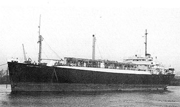
In 1953 the first specially designed LPG gas carrier was constructed. The Rasmus Tholstrup used cylindrical tanks, mounted vertically, to provide a total storage capacity of 1 042 m3.
In 1959 the Descartes was the first gas carrier to be constructed with a refrigeration plant. The 2 100 m3 vessel was constructed in France at Chantiers Naval de La Ciotat. In 1967, the same French yard built the 6 310 m3 Pascal, which was the first ship capable of carrying either The Liquefied Gas Tanker typessemi-refrigerated or The Liquefied Gas Tanker typesfully refrigerated cargoes in semi-pressurised tanks.
It was the North Thames Gas Board’s “Canvey Island Project” study into the feasibility of carrying LNG in large tanks at near atmospheric pressure which directly resulted in the same design of ship being proposed for LPG transport. While the Methane Pioneer, which was converted from a Liberty Ship, started trading in 1959, it was not until 1962 that the first purpose built fully refrigerated LPG carrier was completed. This was the 28,875 m3 Bridgestone Maru built by Mitsubishi at Yokohama, Japan. She was designed to carry propane and butane at atmospheric pressure at minus 41 °C.

This was followed in 1964 by the 36 000 m3 Bridgestone Maru 11. This ship was constructed at the same yard but with an improved system of cargo tank supports. In 1966, the 46 720 m3 Bridgestone Maru III was built at the Japanese yard Ishikawajima-Harima Heavy Industries (IHI) using the improved Bridgestone support design. The first European fully refrigerated LPG carrier was the 25 012 m3 Paul Endecott built at Kockums in 1964. This ship comprised five self-supporting prismatic tanks to carry LPG, ammonia (NH3) or ethylene oxide at a minimum temperature of minus 51 °C. Kockums followed this design with the 26 500 m3 Phillips Arkansas in 1969.
As of January 2008, there are 1 708 LPG gas carriers currently listed in the Lloyd’s Register Class Direct LIVE database. Thirty years ago, as of early 1978, the world fleet of LPG carriers stood at 517 ships.
Design parameters
Ship types
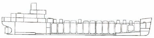
LPG cargo tanks are formed using a separate structure from the ship’s external hull. These tanks are termed “independent” and do not contribute to the hull strength.
There are three different types of independent tank:
- Independent tanks, type A (MARVS < 0,7 bar)Type A, where the tank primarily consists of flat surfaces, is designed using classical ship structural analysis techniques. The design vapour pressure is limited to 0,7 bar g, which means that the cargoes must be carried in a fully refrigerated condition. The cargo tanks require a full secondary barrier.
- Independent tanks, type B (MARVS < 0,7 bar)Type B is designed using model tests, refined analytical tools and analysis methods to determine deformation, buckling, fatigue failure and crack propagation. Normally limited to LNG gas carriers and only a partial secondary barrier is required.
- Independent tanks, type C (MARVS < 0,7 bar)Type C cargo tank design also meets standard pressure vessel acceptance criteria. Tanks may be spherical, cylindrical or bi-lobe design. The selected design needs to best utilise the hull volume. A bi-lobe type tank is formed from intersecting cylindrical pressure vessels and improves utilisation of the hull volume. If insulated and fitted with a reliquefaction system, the design vapour pressure may be limited to around 5 bar g, which allows the scantlings of the cargo tanks to be greatly reduced. These cargo tanks do not require a secondary barrier.
LPG Cargoes
From the above table it should be noted that all gases described as LPG occur as gases at normal temperature and pressure (NPT) of 0 °C and 1,01325 × 10⁵ pascals. Thus, they are required to be cooled and or pressurised to maintain them in liquid form.
All the above cargoes are listed in Chapter 19 of the IGC Code. It should be noted that isoprene is also classed as a chemical and thus covered by the IBC Code.
The low temperature ethane and ethylene may be carried in either the Type A or Type C ship design. The mode of operation of the reliquefaction plant is a direct system as used for the “normal” cargoes listed in Table No. 2, however, when a low temperature cargoes is carried, an additional condenser is fitted with an independent refrigeration circuit. The boil-off gas passes through the sea water-cooled condenser, which acts as a desuperheater, and then the refrigerant condenser. This allows the ethane or ethylene to condense at a suitable low temperature to be re-injected into the cargo tanks.
Reliquefaction plant design development
Of the LPG cargoes originally defined by the API, – propane, butanes, propylene and butylene – propane and butane were by far the most common products transported. This was done using pressurised tanks in the 1940s and 1950s. In the early 1950s Société Maritime Shell investigated the possibility of cooling the cargo to increase the density and thus the pay load.
The Butagaz, fitted with 36 vertical cylindrical tanks, is credited to have carried the first cooled LPG cargoes. The forward hold was lined with expanded PVC insulation bricks and the space was cooled using a second-hand refrigeration compressor and heat exchanger. The results of the experiment were considered to be sufficiently encouraging to demonstrate that the proposed idea could be successful.
Société Maritime Shell is again credited as the pioneer of using a dedicated direct refrigeration system in conjunction with a secondary refrigerant circuit. The ship was a modified product tanker, the Iridina, and while the cargo in question was butadiene, which has a boiling point of minus 4,4 °C, the cargo tanks still needed to be insulated. Only the central tanks were used for the carriage of the cargo and these had insulation fitted internally. This consisted of hardwood planks covered with mild steel sheets and fibreglass covered by wire mesh fitted to the deck structure. However, the transverse bulkheads remained uninsulated with the exception of a three foot (0,9 m) ribb and which was sprayed with polyurethane foam.
The cargo was maintained at atmospheric pressure by brine cooling coils located in the vapour space at the top of each insulated tank. The cargo vapour condensed on the cooling coil and dropped back into the tank. The brine was circulated through an evaporator which was in turn was cooled by a refrigeration plant. The system was similar to that used on reefer ships. While Iridina was limited to the carriage of butadiene and butane it should be noted that she was also the first to use a membrane containment system.

The reliquefaction plants use on the early semi-pressurised designs, such as the 1965 Tamanas (Caribgas 7), utilised standard refrigeration compressors, such as those manufactured by Thomas Sabroe & Co. These were used to extract the boil-off gas from the cylindrical cargo tank’s vapour space and condense it in a sea water cooled shell and tube condenser before returning it to the cargo tanks. Multiple compressors and condensers were provided to allow some redundancy but standard practice was to only carry one grade of cargo. As well as LPG gases the class notations at the time stated, “Ammonia or petroleum gases in independent tanks”.
The early fully refrigerated ships again followed the design of reliquefaction system used on the semi-pressurised ships. The Clerk-Maxwell, constructed by Hawthorn Leslie in 1966, used three eight-cylinder J&E Hall Ltd reciprocating compressors serving three shell and tube condensers. Again they reliquefied the boil-off directly; however, the three separate “units” provided the ability to carry two different cargoes with the third unit providing a standby. The class notation in this instance stated, “Propane, butane, butadiene or anhydrous ammonia in independent tanks”.
Further developments continued with the design of reliquefaction plant. The dedicated ammonia carrier Deneb, built in 1968, utilised a cascade reliquefaction system. This used J&E Hall Ltd reciprocating compressors for both the refrigerant circuit, which contained R-22, and the cargo gas circuit. The ammonia boil-off gas was extracted from the cargo tanks using three six cylinder and then condensed in a shell and tube cargo heat exchanger which acted as the evaporator of the refrigerant circuit. The refrigeration circuit also consisted of three six cylinder machines, of greater swept volume, and the circuit completed using a sea water cooled shell and tube condenser.
Just to complete the development, the Wiltshire, built in 1968 by Swan Hunters at Hebburn, had a similar cascade system to the Deneb but used oil-less Sulzer reciprocating compressors on the cargo gas system and Thomas Sabroe & Co machines on the refrigeration circuit. The use of the oil-less compressor design allows the cargo to remain pure without any oil residue being returned to the cargo tanks. Three separate “units” were provided to allow the ship the ability to carry two different grades of cargo. As the design of the containment system and reliquefaction plant allowed a minimum cargo temperature of minus 50 °C, this allowed the class notation to be expanded to include the lower boiling point of propylene.
Reliquefaction plant
Background
The use of ammonia in vapour compression refrigeration equipment was patented by Karl von Linde in 1873 for use in land-based refrigerated food stores. In 1895 he also built the first commercial scale air liquefier which used an adiabatic expansion valve to provide a refrigeration duty due to the Joules-Thompson effect.
The reliquefaction system follows the same basic thermodynamic theory as a refrigeration circuit. This basic theory will not be covered in this paper. For those wanting an insight into the thermodynamic principles, Appendix 3 of the International Chamber of Shipping’s Tanker Safety Guide (Liquefied Gas) is an excellent starting point.
If the boil-off gas produced in the cargo tanks is considered the same as the vapour generated in the evaporator of a refrigeration circuit, then there is no difference between a LPG reliquefaction system and a standard low temperature refrigeration system.
Instead of the evaporator removing heat from air or brine the heat being removed in a reliquefaction system is that which has ingressed through the insulation system. Other sources of energy which result in boil-off are mechanical energy due to sloshing, electrical energy converted into heat in the cargo pumps and heat energy extracted from the containment system prior to and during loading. Other energy source can be from the cargo itself if it is loaded “warm” and heat ingress through loading arms and liquid headers.
The reliquefaction system can perform other functions such as supplying high pressure compressor discharge gas to blow standing liquid out of loading and discharge lines or proving hot gas to puddle heat the remaining liquid in cargo tanks prior to inerting and gas freeing.
Simple direct reliquefaction system
Figure 6 shows a typical cargo gas reliquefaction plant which is known as a direct open circuit. During normal sea-going loaded operations, the vapour produced due to the heat ingress through the insulation of the containment system, boils the cargo adjacent to the tank wall, nucleate bubbles then form and rise to the surface of the liquid. The vapour within the bubbles increases the pressure within the vapour space which has a fixed volume. The low pressure (150 mbar) boil-off is drawn off by the compressor suction. It then flows through a suction accumulator (knock-out pot) to remove any entrained liquid and liquid droplets, before entering the compressor.
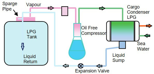
The vapour is compressed in the oil-free compressor. This is a double acting reciprocating compressor and may be of either a vertical or horizontal design.
Depending on the cargo being carried, it may be:
- single stage, for high boiling point cargoes such as butane, or,
- multi-stage for low pointing point cargoes such as propane.
From the compressor, the super-heated high temperature and high pressure vapour is condensed in the sea water cooled condenser. The temperature and pressure is dependent on the cargo carried. The boil-off vapour is now condensed to liquid and is collected in a sump or separate condensate receiver. The liquid is still at high pressure but at a temperature only slightly higher than that of the condensing medium. The liquid is then expanded through a control valve, with a resulting reduction in pressure and temperature. After the expansion device, the fluid returned to the cargo tank contains sub-cooled liquid and a small proportion of flash gas.
This type of system, in single stage form, can be used on semi-pressurised Type C gas carriers for the high boiling point cargoes kept at near atmospheric pressure and low boiling point cargoes if they are maintained at a semi-pressurised condition. A modern multi-stage direct system is discussed later.
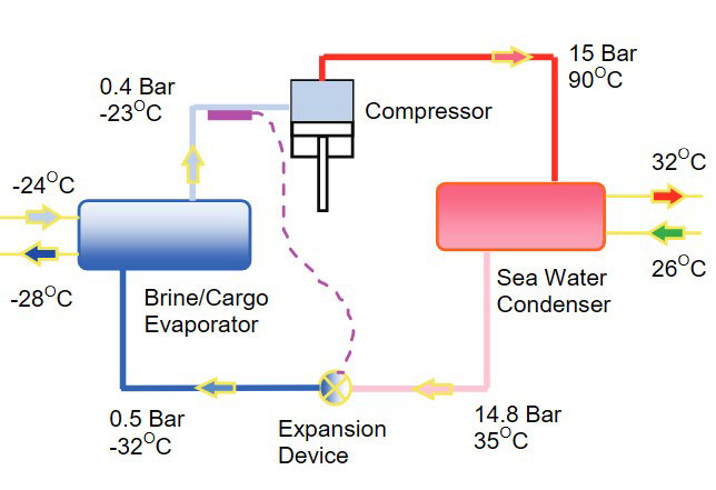
Traditional cascade reliquefaction system
The traditional cascade system closely follows the single stage direct system described above, with the exception that the seal water condenser is replaced by a refrigerant cooled cargo gas condenser.
The refrigeration circuit of this system is similar to the simple refrigeration circuit described above. In the early cascade systems, the refrigeration compressors were of the reciprocating type, however, these were upstaged by more efficient and maintenance friendly economised screw compressors.
This design of system was common on the larger Type A fully refrigerated gas carriers. The advantages were that the design was more efficient than a direct system so the size of the expensive oil-free reliquefaction compressor could be greatly reduced. The system could also be fitted with capacity control thus allowing the system to still operate optimally for different cargoes.
Modern direct system
In a direct system, the condensing temperature quantifies the maximum duty obtainable from the installed compressors. Sea water is normally the condensing medium. This allows compliance with the IGC Code requirement that cooling water is not returned to the engine room. Therefore, it is the temperature of the sea water which controls the condensing temperature. Even by fitting oversized condensers, it is unlikely that a substantial advantage could be obtained. The direct reliquefaction plant works hardest during cargo loading. As loading ports are typically in locations such as the Gulf, which experience high sea water temperature, it is standard practice to utilise the standby machine to assist in cooling down prior to loading.
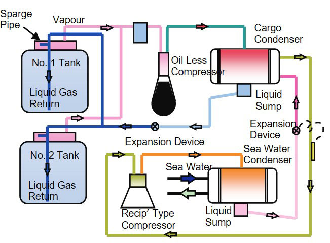
There are design limitations to be considered with regard to the oil-free compressor. If low boiling point cargoes are to be carried, then there is a need to two-stage and possibly three-stage the compressor. The maximum compression ratio for a single stage machine is around 6:1 before the efficiency starts to drop away. Thus if propane is carried, it is normal practice to operate the compressor in a two- or three-stage mode to obtain acceptable efficiency.
As the volume of cargo carried increases so must the capacity of the reliquefaction plant. The current design of oil-free compressors is limited by their physical size and speed. Thus the only way to keep up with required reliquefaction capacity is to increase the number of machines. Where plant designs having three compressor sets are traditional, thus allowing two different grades of cargo to be carried, the current trend is to have four units.
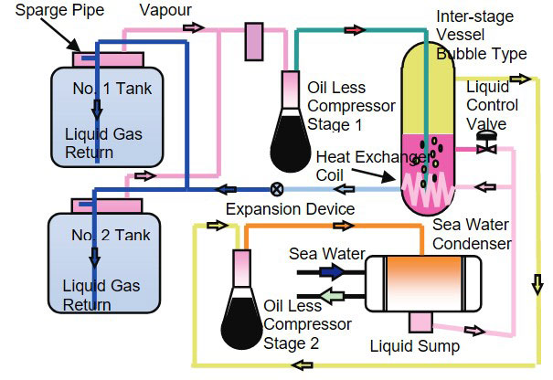
Single verses multi-stage direct system
The need to operate the reliquefaction plant as single stage or multi-stage depends on the cargo being carried. Following good working practice, in tropical zones the condensing temperature is considered to be 8 K above the cooling water inlet temperature. This results in a compressor discharge pressure equivalent to 40 °C. This is in line with the maximum sea water temperature of 32 °C as stated in the IGC Code.
If the 6:1 compression ratio limitation is followed, Table No. 4 shows which cargoes can and cannot be carried with the reliquefaction system operating in single stage mode.
Another variable to be considered is the volume of boil-off gas to be reliquefied. It is not only heat ingress through the containment system and mechanical energy due to sloshing which needs to be considered. The latent heat of evaporation and density of the vapour also affects the cooling duty that the compressor can achieve.
Sizing the reliquefaction plant
The method by which reliquefaction plants are sized is mainly dependent on the heat ingress through the insulation surrounding the cargo tanks.
Other aspects which need to be taken into consideration are:
- Mechanical energy due to sloshing.
- Heat ingress through pipe headers.
- Heat removed from containment system.
- Safety factor required by Class.
Figure No. 9 shows data which has been collated from all the Lloyd’s Register classed Type A LPG vessels constructed up and including 1983. The reason why this graph contains old data is that it shows the economy of scale achieved with the older generation of ships having the highest ratio. It should be noted that reliquefaction duties have been amended so as to take the standby unit out of the equation.

As a means of calculating the required size of the reliquefaction plant, the Lloyd’s Register computer model has been used. The model is normally used to independently verify boil-off rates of vessels being classed. A 50 000 m3 four tank model ship having 120 mm of polyurethane insulation and following typical construction practises has been modelled. Steady state conditions have only been considered with.
- Heat ingress through the cargo tanks containment system.
- An allowance based on empirical data allowed for heavy sea (worst case) sloshing.
- The required five per cent safety margin.
With regard to sloshing, no account of differences in cargo density and viscosity has been considered. Various cargoes have been considered and the results are shown in Table No. 5.
If the above total duties are then converted to the volume flow which is required to be pumped by the compressor, then commercial propane will require the largest compressor swept volume. For the value of 278,5 kW the volume flow rate would be 1,090 m³/h (0,303 m³/s). It should be noted that this figure does not included the additional capacity required to deal with cargo loading conditions.
Indirect refrigeration systems
There are a number of cargo is listed in the IGC Code which require an indirect refrigeration system to be fitted. These are the cargoes which are classed as “1G”, they include chlorine, methyl bromide and sulphur dioxide and require the maximum preventative measures to preclude escape of the cargo. Other cargoes which readily form dangerous peroxides can also be carried using an indirect system to alleviate the possibility of stagnant pools forming.
This design of system consists of a typical refrigeration system with the evaporator, which condenses the vapour located within the vapour space. The evaporator takes the form of a serpentine coil in which the refrigerant is expanded. The boil-off gas condenses on the outside of the coil and falls back into the tank. This is considered a refrigeration system and not a reliquefaction plant.
Future options
As the size of LPG carriers continues to increase, the size of the reliquefaction plant will need to increase proportionally. Whereas, through the proportion of scale, the area of tank surface to volume being carried will assist in decreasing the percentage boil-off rate, the actual refrigeration load will continue to increase. As LNG carriers are now being built up to 260 000 m³ it is considered that the 120 000 m³ LPG carrier design may soon be followed by 160 000 m³ vessels.
If this size of ship were to be fitted with a direct cargo gas system, then either a very large oil-free compressor would be needed or twice as many existing compressor designs would need to be fitted. If larger machines are contemplated, then there is the knock-on effect of greater generating capacity being required to handle the starting currents. The present trend is for sufficient electrical power to be provided to run either the cargo pumps or the reliquefaction plant. Upsetting this balance would create substantial additional cost for the increase in generating power and compressor motor size.
One way round this predicament would be to revert back to the traditional cascade system. While the traditionally used hydro chlorofluorocarbon (HCFC) R-22 has been banned under the Montreal Protocol, there are other refrigerants such as the hydrofluorocarbons (HFCs) or hydrocarbons such as propane. This would allow the same oil-free compressors, as used on the current 80 000 m³ LPG ships, to be used and the additional heat load associated with a 160 000 m³ gas carrier would be rejected from the refrigeration circuits.
Another option is the use of LPG as a fuel. This is discussed further in Risks and Compliance for Environment for Liquefied Petroleum Gas Operations within Inland Waterwaysthis article.
Different cargo requirements
Butadiene
Butadiene is carried in an inhibited condition by the addition of chemical stabilisers. As the inhibitors are ineffective in the vapour phase, the presence of contaminants such as rust must be minimised. In order to prevent rates of polymerisation increasing the reliquefaction compressor discharge temperature must be restricted to 60 °C.
Since there is the possibility of butadiene condensing in the intermediate stage during multi-stage operation it is advisable to utilise single-stage operation where possible.
Prior to opening up the reliquefaction compressor after carrying butadiene, the unit should be fully purged with dry inert gas.
Butadiene is not compatible with many synthetic lubricating oils and so the compressor and oil manufacturers’ recommendations should be followed. If butadiene is to be regularly carried, the oil may be drained into closed containers and be reused.
Vinyl chloride monomer (VCM)
In order to prevent polymerisation, the reliquefaction compressor discharge temperature must be restricted to 90 °C. (This is to prevent serious damage to the machine).
If water vapour is present in the machine VCM will form a corrosive hydrochloric acid solution. It is therefore necessary for the machine to be inerted using dry inert gas.
When changing cargoes from VCM to butadiene, the oil in the compressor crankcases may need to be changed because the entrained VCM will slowly boil off into the crankcase and cargo and cause a commercially unacceptable concentration.
Ammonia
When changing cargoes from ammonia to either butadiene or VCM the oil in the compressor crankcases may need to be changed as the entrained ammonia will slowly boil off into the crankcase and cargo and cause a commercially unacceptable concentration.
Inert gas which contains carbon dioxide must not be used to gas free cargo tanks which have contained ammonia because a white salt will form and adhere to the internal surfaces of the tank and pipework. Direct ventilation with air may be undertaken.
Isoprene
Isoprene has a boiling point of 34,1 °C at atmospheric pressure. In cold ambient conditions there may be a need to heat and vaporise cargo to stop a partial vacuum from forming in the cargo tank. Flame screens must be fitted to vent outlets when carrying this cargo. If the cargo tanks are fitted with submerged cargo pumps the vapour space must be inerted to a positive pressure at all times.
Methyl acetylene/propadiene mixtures
Preferably, the reliquefaction system should be of the indirect type. If a direct type is used special consideration needs to be given to the compressor throughput to limit the head pressures to 17,5 bar g and the discharge temperatures to 60 °C. Compressor high discharge temperature and high discharge pressure alarm and shut downs should be fitted.
Propylene oxide
The reliquefaction system needs to be an indirect type. Flame screens must be fitted to vent outlets when carrying this cargo. This cargo should not be carried in cargo tanks which have previously contained other cargoes unless they have been thoroughly and effectively cleaned. Special consideration needs to be given when the previous cargo was ammonia. Internal filling and discharge pipework is to extend to within 100 mm of the bottom of the tank or sump. As propylene oxide has a boiling point of 34,3 °C at atmospheric pressure, it is possible that a partial vacuum may form in the cargo tank during extended periods at low ambient temperatures.
Cargo tanks carrying propylene oxide should be independently ventilated. The piping systems for tanks loaded with propylene oxide are to be separate from the piping system for other tanks and the reliquefaction system must be isolated and suitably sealed. All cargo hoses used for propylene oxide are to be suitably marked as such. Appropriately endorsed cargo handling plans are to be retained on board. The inert gas system used for padding the cargo needs to be fully automatic to provide nitrogen of commercially pure quality (99,9 % pure).
Ethylene oxide/propylene oxide mixtures
The reliquefaction system needs to be of the indirect type. Flame screens must be fitted to vent outlets when carrying this cargo. This cargo should not be carried in cargo tanks which have previously contained other cargoes unless they have been thoroughly and effectively cleaned. Special consideration needs to be give when the previous cargo is ammonia. Internal filling and discharge pipework is to extend to within 100 mm of the bottom of the tank or sump.
Cargo tanks carrying ethylene oxide/propylene oxide mixtures should be independently ventilated. The piping systems for tanks loaded with ethylene oxide/propylene oxide mixtures are to be separate from the piping system for other tanks and the reliquefaction system must be isolated and suitably sealed. All cargo hoses used for ethylene oxide/propylene oxide mixtures are to be suitably marked. Suitably endorsed cargo handling plans are to be retained on board. The inert gas system used for padding the cargo needs to be fully automatic and provide nitrogen of commercially pure quality (99,9 % pure).
Methanol injection
To free up cargo pumps or de-ice control injection valve orifices, methanol may be injected. If water is present in the cargo (that is the cargo is hydrated), ice will form especially where a pressure drop occurs.
Injection of methanol will cause contamination of the cargo and should only be undertaken if all charter parties are in agreement.
Inhibited cargoes
The inhibitor is in a liquid form and remains in solution with the liquid cargo. The vapour taken by the reliquefaction compressors does not contain any inhibitor and thus when the vapour is condensed “neat” cargo accumulates in the condenser. Therefore, all condensate return lines and the condenser should be emptied when the reliquefaction plant is not in use.
Hot gas vapour is normally used to clear the lines if a reliquefaction plant is operational. If all plants are stopped, nitrogen should be used for this purpose. If this is not acceptable a small amount of additional inhibitor may be injected into the condenser shortly before stopping the machines.
Injecting additional inhibitor will alter the overall inhibitor concentration and should only be undertaken if all charter parties and owners are in agreement.
Equipment
Cargo compressors
The materials used in the compressor, including “O” rings and gasket materials, are to be suitable for the proposed cargoes. If a bulkhead seal is fitted between the gas safe motor room and the gas dangerous compressor room, it is to be suitably lubricated or supplied with seal gas to ensure a permanent seal. The seal is also to be fitted with a temperature alarm.

The high discharge temperature alarm fitted to the discharge outlet is to be adjustable depending on the temperature of the cargo carried. On older installations separate high temperature alarms were fitted and a mode switch fitted to activate the correct alarm set point depending on the cargo carried, normal 120 °C, VCM 90 °C and Butadiene 60 °C.
On multi-cylinder machines, which can allow single and multi-stage operation, a capacity selector switch is also fitted to allow reduced capacity when the higher boiling point cargo is carried. This capacity control, operated by lifting the suction valve plates, is also used when starting the compressor as it would allow the compressor motor starting current to be much reduced.
Refrigeration compressors
These are standard marine refrigeration compressors as normally fitted to reefer ships and porthole type container ships. Originally, reciprocating compressors were used but these were phased out as the double and single helical screw machines became accepted.
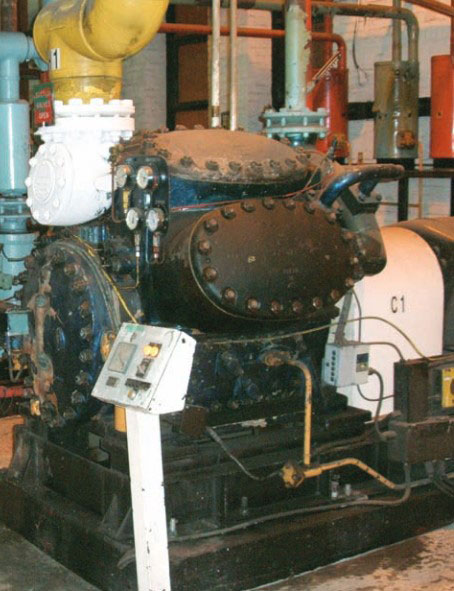
It is considered that only the economised double helical screw compressors would now be considered due to their lower maintenance requirements and greater efficiency. The improvement in efficiency arises from the ability to readily adjust the internal volume ratio of the compressor to suit all proposed cargoes.
Heat exchangers
Heat exchangers are the sea water condensers in direct systems and the cargo and sea water refrigerant condenser in cascade systems. Whereas historically, shell and tube heat exchangers were used, the use of plate type heat exchangers is now more common. The material of the plates or tubes, tube sheets and shell must be compatible with the cargoes being carried. If ammonia is carried, some materials must be given a post-weld stress relief heat treatment to prevent stress corrosion cracking.
As a minimum, two separate condenser cooling water pumps are to be installed. One of the pumps may be considered as a standby and may be used for other purposes, provided that it is of adequate capacity and its use on other services does not interfere with the supply of cooling water to the condensers. The cooling water pumps are to be served by no less than two sea inlets. It is recommended that the sea inlets be provided on each side of the ship.
Purger
After gassing-up, a small proportion of inert gas remains in the cargo tanks. The proportion is dependent on the time and care taken during the gassing-up procedure. The inert gas is then circulated through the reliquefaction system during the cooling down process. This inert gas, mainly nitrogen and oxygen, is non-condensable in the reliquefaction system and is thus returned to the cargo tank in the gaseous phase. Nitrogen has a boiling point of minus 195,8 °C and oxygen minus 182,6 °C at atmospheric pressure.
If this inert gas is not removed from the vapour space of the cargo tanks it has the effect of reducing the efficiency of the reliquefaction system by increasing the condensing pressure. These non-condensable gases tend to collect in the top of the cargo condenser. Thus either a purge valve or automatic purger needs to be fitted to remove them. In the past, normal practice was to crack open the vent valve on the top of the condenser which ran to the relief valve vent mast. Due to the restriction in venting hydrocarbons, an automatic purger should now be fitted. The purger will condense any cargo in the vent stream and only allows the non-condensable gases to be discharged to the vent mast.
Suction separator (knock-out pot)
This is provided to reduce the possibility of liquid or liquid droplets entering the suction of reciprocating reliquefaction compressor. If the ship is in heavy seas, and considerable sloshing occurs, then without a suction separator vessel liquid could enter the vapour line to the compressor.
The suction separator takes the form of a vertical cylindrical pressure vessel with the suction line entering the top of the vessel and continuing internally almost to the bottom of the vessel. The take-off to the compressor to taken from the side of the vessel, close to the upper tan line. The vessel is normally fitted with some form of internal baffling or mesh to collect any droplets of liquid and hence reduce carry-over. It is also fitted with a high level alarm and means to allow drainage.
Other options – LPG as a fuel
The use of LPG as a fuel in diesel generator engines has already been proposed. Such a system has been developed by Lauritzen Kosan in conjunction with MAN Diesel (Holeby). This system is currently being installed in a series of Type C ethylene carriers under construction at Sekwang Heavy Industries in South Korea.
The system provides a fuel “top-up” facility for a single alternator diesel engine. The LPG gas is only used when the engine is operating within a specific comfort zone and not at the extremities of its maximum continuous rating (MCR). The system is an “incinerator system” for waste LPG, used in connection with change of cargo. After discharge, the remaining heel of cargo is condensed into an ISO 20-foot LPG tank container. The liquid is passed through a heater and a knock-out pot, before the vapour is injected into the charge air stream of the dedicated auxiliary engine, to allow “environmental incineration”. This allows six different products or mixtures to be incinerated in an environmentally friendly method. This system is not currently seen as a replacement for reliquefaction.
The IGC Code states that methane (LNG) is the only cargo whose vapour or boil-off gas may be used in category A machinery spaces. Category A spaces are defined in SOLAS Chapter II-2, Regulation 3. The requirements of the United States Coast Guard (USCG) 46 Code of Federal Regulations (CFR) 154 701-709 also does not allow gases other than LNG to be used in combustion machinery. Thus permission would also need to be obtained from the USCG for using LPG as a fuel when in US controlled waters.
If LPG cargoes are to be used as fuel, then the space housing the fuel burning equipment cannot be considered as a Category A space and would need to comply with special considerations. This then means that a negatively ventilated dedicated space, housing the LPG burning equipment, would need to be provided. This assists in meeting the other requirements of the IGC Code, namely gas detection and ventilation systems.
As LPG gases are heavier than air at room temperature both the ventilation outlets and gas detectors would need to be mounted at low level. Various safety systems would need to be installed to safeguard adjacent machinery spaces such as a device to trip the gas master valve in the event of loss of pressure differential between the negatively ventilated gas burning room and adjacent spaces.
Concluding remarks
The design of LPG reliquefaction plants has not altered significantly since the first fully refrigerated gas carriers came into being. The option of a direct system, utilising the cargo gas, and a cascade system, using a separate refrigeration circuit, both remain current.
As the size of LPG gas carriers continues to increase there may well be a shift back to the traditional cascade systems, which have a separate refrigeration circuit.
The machinery used will continue with oil-free compressors, whether of the horizontal or vertical type. The development of an extremely high efficiency oil separator, having an oil carry-over of one part per million (ppm) or less, might allow the use of standard refrigeration compressors.
The use of LPG as a fuel may be a way forward. The impending rewrite of the IGC Code would be the ideal time to propose Rules for this application. However, acceptance by the USCG is a different matter this would also need to be obtained to allow trading using this type of system in US controlled waters.