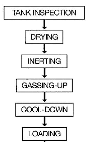
Before the next loading of gas, tanks should be prepared. This article will help you to create your cargo tank inspection check list.
- Methods of control
- Warming up
- Drying using inert gas from the shore
- Drying using inert gas from ship’s plant
- On board air-drying systems
- Inerting
- Inerting by displacement
- Inerting by dilution
- Inert gas – general considerations
- Inerting prior to loading ammonia
- Gassing-up
- Gassing-up at sea using liquid from deck storage tanks
- Gassing-up alongside
- Cooling down
- Cool-down – refrigerated ship
- Cool-down – semi-pressurised ships
Methods of control
Before any cargo operations are carried out it is essential that cargo tanks be thoroughly inspected for cleanliness; that all loose objects are removed; and that all fittings are properly secured. In addition, any free water must be removed. Once this inspection has been completed, the cargo tank should be securely closed and air-drying operations may start.
Warming up
Drying the cargo handling system in any refrigerated ship is a necessary precursor to loading. This means that water vapour and free water must all be removed from the system. If this is not done, the residual moisture can cause problems with icing and hydrate formation within the cargo system.
The reasons are clear when it is appreciated that the quantity of water condensed when cooling down a 1 000 m3 tank containing air at atmospheric pressure, 30 °C and 100 % humidity to 0 °C would be 25 litres.
Whatever method is adopted for drying, care must be taken to achieve the correct dew point temperature. Malfunction of valves and pumps due to ice or hydrate formation can often result from an inadequately dried system. While the addition of antifreeze may be possible to allow freezing point depression at deep-well pump suctions, such a procedure must not substitute for thorough drying.
Antifreeze is only used on cargoes down to -48 °C; propanol is used as a de-icer down to -108 °C but below this temperature, for cargoes such as LNG, no de-icer is effective.
Tank atmosphere drying can be accomplished in several ways. These are described below.
Drying using inert gas from the shore
Drying may be carried out as part of the inerting procedure when taking inert gas from the shore. This method has the advantage of providing the dual functions of lowering the moisture content in tank atmospheres to the required dew point and, at the same time, lowering the oxygen content.
A disadvantage of this and the following method is that more inert gas is used than if it is simply a question of reducing the oxygen content to a particular value.
Drying using inert gas from ship’s plant
Drying can also be accomplished at the same time as the inerting operation when using the ship’s inert gas generator but satisfactory water vapour removal is dependent on the specification of the inert gas system. Here, the generator must be of suitable capacity and the inert gas of suitable quality – but the necessary specifications are not always a design feature of this equipment.
The ship’s inert gas generator is sometimes provided with both a refrigerated dryer and an adsorption drier which, taken together, can reduce dew points at atmospheric pressure to -45 °C or below.
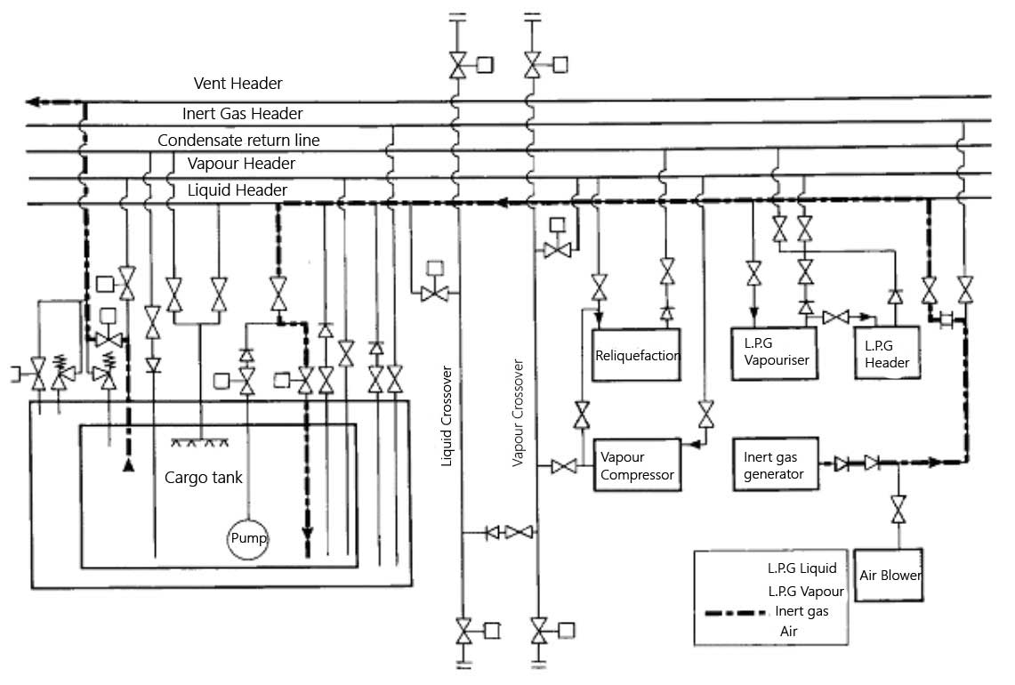
On board air-drying systems
An alternative to drying with inert gas is by means of an air-drier fitted on board. The principle of operation is shown in Picture 2. In this method, air is drawn from the cargo tank by a compressor or provided by the on board inert gas blower (without combustion) and passed through a refrigerated drier. The drier is normally cooled by R22 refrigerant. Here the air is cooled and the water vapour is condensed out and drained off. The air leaving the drier is, therefore, saturated at a lower dew point.

A silica gel after-drier fitted downstream can achieve further reduction of the dew point. Thereafter, the air may be warmed back to ambient conditions by means of an air heater and returned to the cargo tank. This process is continued for all ship tanks (and pipelines) until the dew point of the in-tank atmosphere is appropriate to carriage conditions.
Inerting
Inerting cargo tanks, cargo machinery and pipelines is undertaken primarily to ensure a non-flammable condition during subsequent gassing-up with cargo. For this purpose, oxygen concentration must be reduced from 21 % to a maximum of five per cent by volume although lower values are often preferred.
However, another reason for inerting is that for some of the more reactive chemical gases, such as vinyl chloride or butadiene, levels of oxygen as low as 0,1 % may be required to avoid a chemical reaction with the incoming vapour. Such low oxygen levels can usually only be achieved by nitrogen inerting provided from the shore There are two procedures, which can be used for inerting cargo tanks:
- displacement;
- dilution.
These procedures are discussed below.
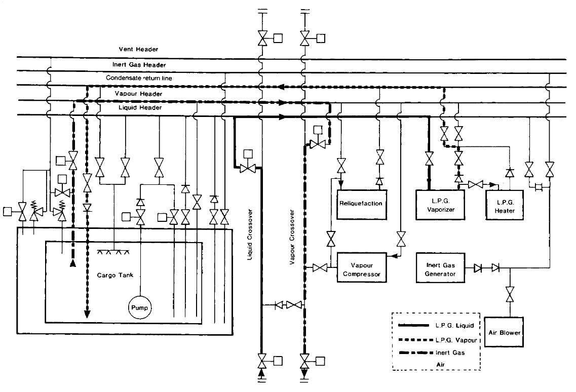
Inerting by displacement
Inerting by displacement, also known as piston purge, relies on stratification of the cargo tank atmosphere based on the difference in vapour densities between the gas entering the tank and the gas already in the tank. The heavier gas is introduced beneath the lighter gas at a low velocity to minimise turbulence. If good stratification can be achieved, with little mixing at the interface, then just one tank volume of the incoming inert gas is sufficient to change the atmosphere.
In practice mixing occurs and it is necessary to use more than one tank-volume of inert gas. This amount may vary by up to four times the tank volume, depending on the relative densities of the gases together with tank and pipeline configurations.
There is little density difference between air and inert gas; inert gas from a combustion generator is slightly heavier than air while nitrogen is slightly lighter. These small density differences make inerting by displacement difficult to achieve and usually the process becomes part displacement and part dilution (discussed below). Combustion-generated inert gas is usually introduced through the liquid loading line with the effluent being exhausted through the vapour line into the vent header.
Picture 3 shows the inerting of a cargo tank by the displacement method.
Inerting by displacement is an economical procedure as it uses the least amount of inert gas and takes the shortest time. However, it is only practical when mixing with the initial tank vapour can be limited. If the tank shape and the position pipe-entries are suitable for the displacement method, then results will be improved by inerting more than one tank at a time. This should be done with the tanks aligned in parallel.
The sharing of the inert gas generator output between tanks reduces gas inlet speeds, so limiting vapour mixing at the interface. At the same time the total inert gas flow increases due to the lower overall flow resistance. Tanks being inerted in this way should be monitored to ensure equal sharing of the inert gas flow.
Inerting by dilution
When inerting a tank by the dilution method, the incoming inert gas mixes, through turbulence, with the gas already in the tank. The dilution method can be carried out in several different ways and these are described below.
Dilution by repeated pressurisation
In the case of Type “C” tanks, inerting by dilution can be achieved through a process of repeated pressurisation. In this case, inert gas is pressurised into the tank using a cargo compressor. This is followed by release of the compressed gases to atmosphere. Each repetition brings the tank nearer and nearer to the oxygen concentration of the inert gas.
Thus, for example, to bring the tank contents to a level of 5 % oxygen within a reasonable number of repetitions, inert gas quality of better than five per cent oxygen is required. It has been found that quicker results will be achieved by more numerous repetitions, each at low pressurisation, than by fewer repetitions at higher pressurisation.
Dilution by repeated vacuum
Type “C” tanks are usually capable of operating under considerable vacuum and, depending on tank design, vacuum-breaking valves are set to permit vacuums in the range from 30 % up to 70 %. Inerting by successive dilutions may be carried out by repeatedly drawing a vacuum on the tank. This is achieved by using the cargo compressor and then, breaking the vacuum with inert gas.
If, for instance, a 50 % vacuum can be drawn, then, on each vacuum cycle, half the oxygen content of the tank is removed. Of course, the oxygen content of the inert gas will replace some of the withdrawn oxygen. Of all the dilution processes, this method can be the most economical as only the minimum quantity of inert gas is used to achieve the desired inerting level.
The overall time taken, however, may be longer than with the pressurisation method because of reduced compressor capacity when working on vacuum and a slow rate of vacuum breaking due to limited output of the inert gas generator.
Continuous dilution
Inerting by dilution can be carried out as a continuous process. Indeed, this is the only diluting process available for Type “A” tanks that have very small over-pressure or vacuum capabilities. For a true dilution process, (as opposed to one aiming at displacement) it is relatively unimportant where the inert gas inlet or the tank efflux is located, provided that good mixing is achieved. Accordingly, it is usually found satisfactory to introduce the inert gas at high speed through the vapour connections and to discharge the gas mixture via the bottom loading lines.
When using the continuous dilution method on ships with Type “C” tanks, increased inert gas flow (and thereby better mixing and reduced overall time) may be achieved by maintaining the tank under vacuum. This is accomplished by drawing the vented gas through the cargo vapour compressor. Under these circumstances care should be taken to ensure good quality inert gas under the increased flow conditions.
Inert gas – general considerations
It can be seen from the preceding paragraphs that inert gas can be used in different ways to achieve inerted cargo tanks. No one method can be identified as the best since the choice will vary with ship design and gas density differences.
Generally, each individual ship should establish its favoured procedure from experience.
As already indicated, the displacement method of inerting is the best but its efficiency depends upon good stratification between the inert gas and the air or vapours to be expelled. Unless the inert gas entry arrangements and the gas density differences are appropriate to stratification, it may be better to opt for a dilution method. This requires fast and turbulent entry of the inert gas, upon which the efficiency of dilution depends.
Whichever method is used, it is important to monitor the oxygen concentration in each tank from time to time, from suitable locations, using the vapour sampling connections provided. In this way, the progress of inerting can be assessed and, eventually, assurance can be given that the whole cargo system is adequately inerted.
While the above discussion on inerting has centered on using an inert gas generator, the same principles apply to the use of nitrogen. The use of nitrogen may be required when preparing tanks for the carriage of chemical gases such as vinyl chloride, ethylene or butadiene. Because of the high cost of nitrogen, the chosen inerting method should be consistent with minimum nitrogen consumption.
Inerting prior to loading ammonia
Modern practice demands that ship’s tanks be inerted with nitrogen prior to loading ammonia. This is so, even though ammonia vapour is not readily ignited. Inert gas from a combustion-type generator must never be used when preparing tanks for ammonia. This is because ammonia reacts with the carbon dioxide in inert gas to produce carbamates.
Accordingly, it is necessary for nitrogen to be taken from the shore as shipboard nitrogen generators are of small capacity. The need for inerting a ship’s tanks prior to loading ammonia is further underscored by a particular hazard associated with spray loading. Liquid ammonia should never be sprayed into a tank containing air, as there is a risk of creating a static charge, which could cause ignition.
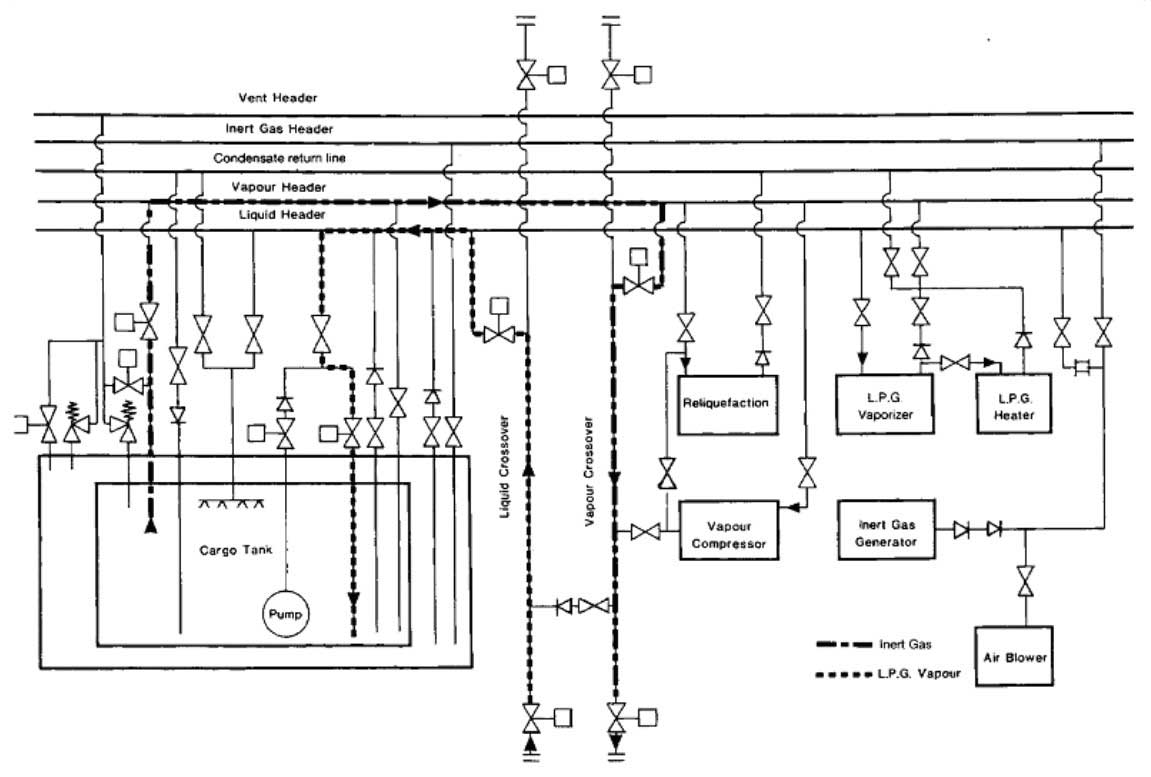
Gassing-up
Neither nitrogen nor carbon dioxide, the main constituents of inert gas, can be condensed by a ship’s reliquefaction plant. This is because, at cargo temperatures, each is above its critical temperature and is, therefore, incondensible. Accordingly, removal of inert gas from the cargo tank is necessary. This is achieved by gassing-up, using vapour from the cargo to be loaded at ambient temperature and venting the incondensibles to atmosphere so that subsequently the reliquefaction plant can operate efficiently.
Similarly, on changing grade, without any intervening inerting, it may first be necessary to remove the vapour of the previous cargo with vapour of the cargo to be loaded. The basic principles discussed previously in respect of inerting methods apply equally to this type of gassing-up.
Gassing-up at sea using liquid from deck storage tanks
Gassing-up at sears a procedure normally only available to fully refrigerated, or semi-pressurised ships. Such carriers are often equipped with deck tanks, which may have a compatible cargo in storage. In this case, either vapour or liquid can be taken from the deck tanks into the cargo tanks.
Liquid can be taken directly from deck storage through the tank sprays (with the exception of ammonia). This is done at a carefully controlled rate to avoid cold liquid striking warm tank surfaces. In this case, vapour mixing occurs in the cargo tanks and the mixed vapours can be taken into other tanks (when purging in series) or exhausted to the vent riser.
Alternatively, liquid from the deck storage tanks can be vaporised in the cargo vaporiser and introduced gradually into the top or bottom of the cargo tank, depending on vapour density, to displace the existing inert gas or vapour to other tanks or to the vent riser.
Only when the concentration of cargo vapour in the tanks has reached approximately 90 % (or as specified by the compressor manufacturer) should the compressor be started and cool-down of the system begin.
Gassing-up alongside
Gassing-up operations, which take place alongside, are undertaken using cargo supplied from the shore. At certain terminals, facilities exist to allow the operation to be carried out alongside but these terminals are in a minority. This is because the venting of hydrocarbon vapours alongside a jetty may present a hazard and is, therefore, prohibited by most terminals and port authorities.
Thus, well before a ship arrives in port with tanks inerted, the following points must be considered by the shipmaster:
- Is venting allowed alongside? If so, what is permissible?
- Is a vapour return facility to a flare available?
- Is liquid or is vapour provided from the terminal for gassing-up?
- Will only one tank be gassed-up and cooled down initially from the shore?
- How much liquid must be taken on board to gas-up and cool-down the remaining tanks?
- Where can the full gassing-up operation be carried out?
Before commencing gassing-up operations alongside, the terminal will normally sample tank atmospheres to check that the oxygen is less than 5 % for LPG cargoes (some terminals require as low as 0,5 %) or the much lower concentrations required for chemical gases such as vinyl chloride.
Where no venting to atmosphere is permitted, a vapour return facility must be provided and used throughout the gassing-up operation. In this case, either the ship’s cargo compressors or a jetty vapour blower can be used to handle the efflux. Some terminals, while prohibiting the venting of cargo vapours, permit the efflux to atmosphere of inert gas. Thus, if a displacement method of gassing-up is used the need for vapour return to shore may be postponed until cargo vapours are detected at the vent riser. This point may be considerably postponed if tanks are gassed-up one after the other in series.
Cooling down
Cool-down – refrigerated ship
Cooling down is necessary to avoid excessive tank pressures (due to flash evaporation) during bulk loading. Cool-down consists of spraying cargo liquid into a tank at a slow rate. The lower the cargo carriage temperature, the more important the cool down procedure becomes. Before loading a refrigerated cargo, ship’s tanks must be cooled down slowly in order to minimise thermal stresses. The rate, at which a cargo tank can be cooled, without creating high thermal stress, depends on the design of the containment system and is typically 10 °C per hour. Reference should always be made to the ship’s operating manual to determine the allowable cool-down rate.
The normal cool-down procedure takes the following form. Cargo liquid from shore (or from deck storage) is gradually introduced into the tanks either through spray lines, if fitted for this purpose, or via the cargo loading lines. The vapours produced by rapid evaporation may be taken ashore or handled in the ship’s reliquefaction plant. Additional liquid is then introduced at a rate depending upon tank pressures and temperatures. If the vapour boil-off is being handled in the ship’s reliquefaction plant, difficulties may be experienced with incondensibles, such as nitrogen, remaining from the inert gas. A close watch should be kept on compressor discharge temperatures and the incondensible gases should be vented from the top of the condenser as required.
As the cargo containment system cools down, the thermal contraction of the tank combined with the drop in temperature around it tend to cause a pressure drop in the hold and interbarrier spaces. Normally, pressure control systems supplying air or inert gas will maintain these spaces at suitable pressures but a watch should be kept on appropriate instruments as the cool-down proceeds.
Cool-down should continue until boil-off eases and liquid begins to form in the bottom of the cargo tanks. This can be seen from temperature sensors.
At this stage, for fully refrigerated ammonia for example, the pool of liquid formed will be at approximately -34 °C while the top of the tank may still be at -14 °C. This gives a temperature difference of 20 °C.
The actual temperature difference depends on the size of the cargo tank and the spray nozzles positions. Difficulties that may occur during cool-down can result from inadequate gassing-up (too much inert gas remaining) or from inadequate drying. In this latter case, ice or hydrates may form and ice-up valves and pump shafts. In such cases, antifreeze can be added, provided the cargo is not put off specification, or the addition will not damage the electrical insulation of a submerged cargo pump.
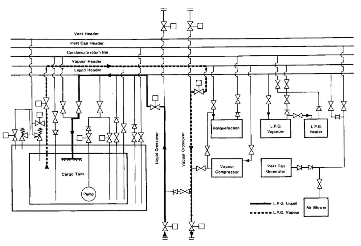
Throughout the cool down, deepwell pump shafts should be turned frequently by hand to prevent the pumps from freezing up. Once the cargo tanks have been cooled down, cargo pipelines and equipment should be cooled down. Picture 5 shows the pipeline arrangement for tank cool-down using liquid supplied from the shore.
Cool-down – semi-pressurised ships
Most semi-pressurised ships have cargo tanks constructed of steels suitable for the minimum temperature of fully refrigerated cargoes. However, care must be taken to avoid subjecting the steel to lower temperatures. it is necessary to maintain a pressure within the cargo tank at least equal to the saturated vapour pressure corresponding to the minimum allowable steel temperature. This can be done by passing the liquid through the cargo vaporiser and introducing vapour into the tank with the cargo compressor. Alternatively, vapour can be provided from the shore.