Gas tank installation requires strict adherence to safety guidelines and regulations. Proper placement, secure mounting, and adequate ventilation are crucial factors to consider. Installers must ensure that tanks are positioned away from heat sources and potential impact zones. Additionally, all connections should be leak-tested and appropriate safety valves must be installed. Regular inspections and maintenance are essential to guarantee the ongoing safety and efficiency of gas tank installations.
- MARK III Containment System Preparation for Installation
- MARK III Containment System Installation Steps
- Conditioning of the Inner Hull
- Cargo Tank Dimensional Tolerances
- Inner Hull Flatness
- Inner Hull Cleanliness and Environment Conditions
- Marking: Reference Lines
- Marking-out of Panels and Stud Positions
- Sensors in Interbarrier Spaces
- Retanier Bars
- Determination of the Reference Surface for Insulation Lay-out
- Preparation of the Reference Surface. Installation of the Reference Wedges.
- Determination of the Reference Surface for the Liquid Dome
Cargo tank insulation plays a vital role in maintaining the temperature and quality of transported materials, especially for cryogenic or temperature-sensitive substances. Effective insulation helps reduce heat transfer, minimizes product loss and enhances overall energy efficiency. Materials such as polyurethane foam, perlite or vacuum-insulated panels are commonly used for cargo tank insulation. The choice of insulation depends on factors like the type of cargo, ambient conditions and regulatory requirements. Proper installation and periodic checks of the insulation system are necessary to ensure its continued effectiveness throughout the tank’s operational life.
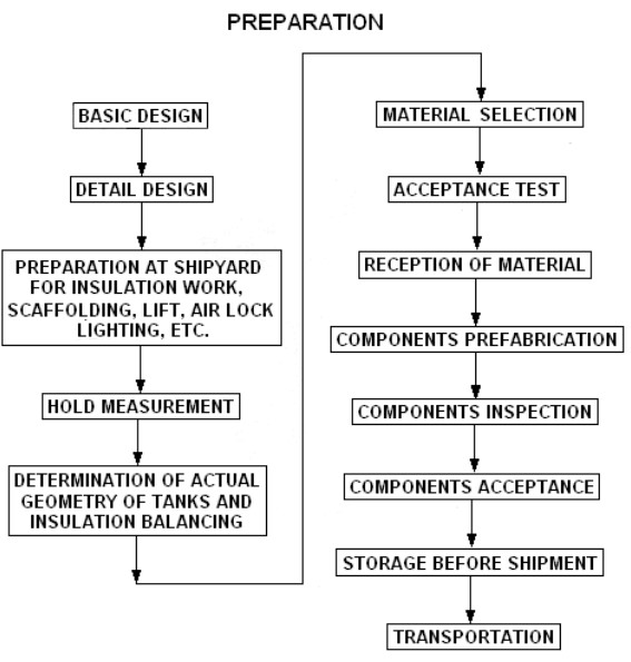
MARK III Containment System Preparation for Installation
Steps necessary in preparation for installation of Cargo containment system of gas vesselcargo containment system is as follows.( See Figure 1.)
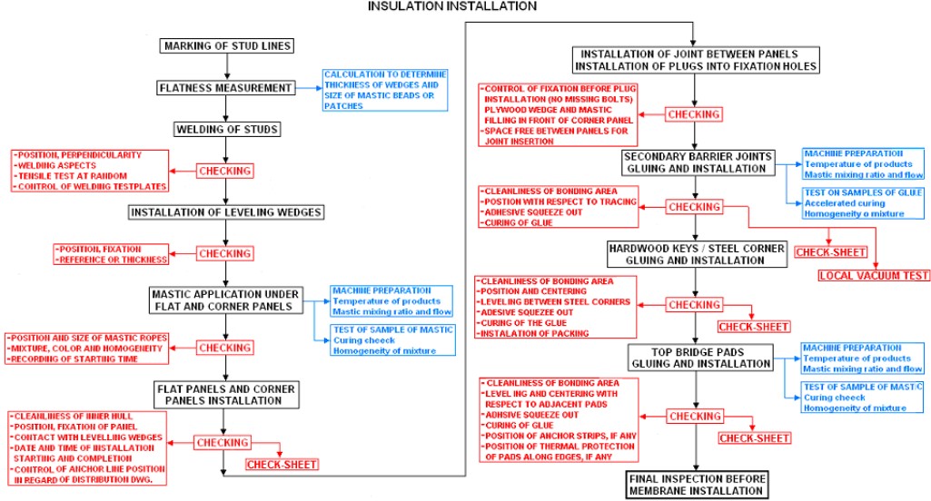
MARK III Containment System Installation Steps
Following flow chart lists the steps necessary for the installation of Mark III containment system. Each of the indicated steps will be further discussed in the next parts of this article. (See Figure 2.)
Conditioning of the Inner Hull
Cargo Tank Dimensional Tolerances
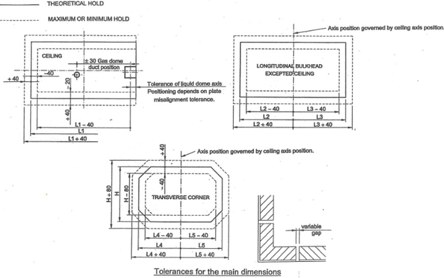
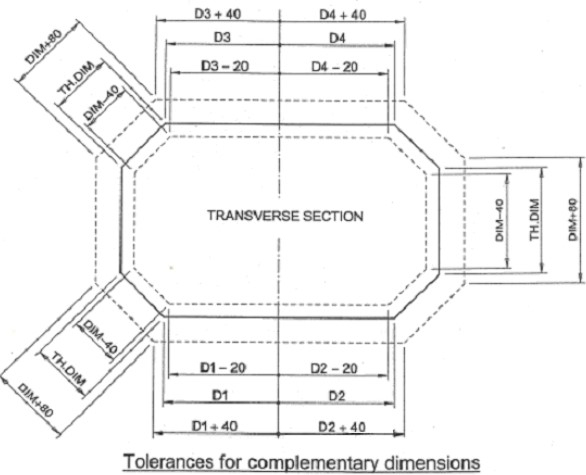
The tolerances of the hull required for the installation of MARK III containment system are fully compatible with the ones that can be matched by the shipyard.
Each bulkhead is defined by its theoretical dimensions, used at the design stage. After erection the final shape and size of the cargo tanks may differ from the theoretical values but they must stay within the tolerances indicated in Figures 3 and 4.
Inner Hull Flatness
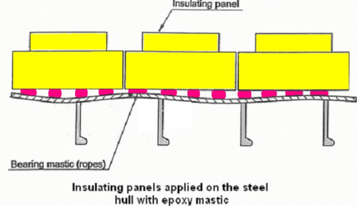
Insulating panels are attached onto the ship’s inner hull through the application of epoxy mastic, which is also used for the leveling of each insulating component (see Figure 5).
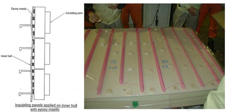
In principle, an inner hull built according to a recognized shipyard/class standard may be used for installation of a cryogenic liner, if within accepted. However, to limit the consumption of mastic (expensive) needed to achieve proper bearing and leveling of the insulation, shipyard must maintain strict adherence to flatness on inner hull.( See Figure 6.)
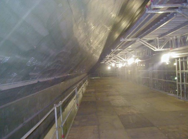
Shipyard should present this plan to minimize distortion of all sub-assemblies, blocks and structures prior to commencement of work. This includes pre-erection and erection joints:
- DURING PREFABRICATION STAGE.
- DURING BLOCK ASSEMBLY AND AFTER COMPLETION OF INNER HULL.
According to the target tolerances to optimize the panel installation, a control procedure should be defined by the shipyard during block prefabrication to confirm steel fitting and welding methods.
At this stage of the ship construction, a specific check of the inner hull flatness should be performed in order to identify and rectify the most pronounced deformations. Otherwise these deformations will be clearly marked on the inner hull and will be listed on a separate document. They will lead to special corrections during epoxy mastic application.
Read also: Characteristics of Different Types of Construction Materials
This control concern four aspects of flatness:
1) OFF-SET OF THE INNER HULL STIFFENERS (Figure 7).
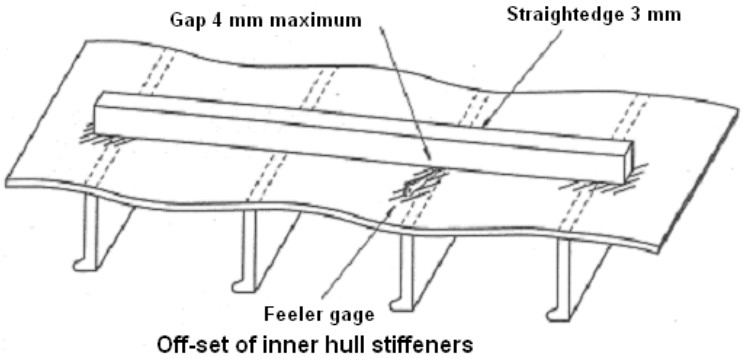
The recommended gap between inner hull and straightedge at the location of the root of stiffeners is 4 mm.
2) DEFORMATION OF THE PLATING BETWEEN HULL STIFFENERS (Figure 8).
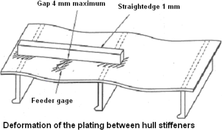
The maximum deformation should be 4 mm.
3) STEEL DEFORMATION ALONG THE BUTT WELDS (Figure 9).
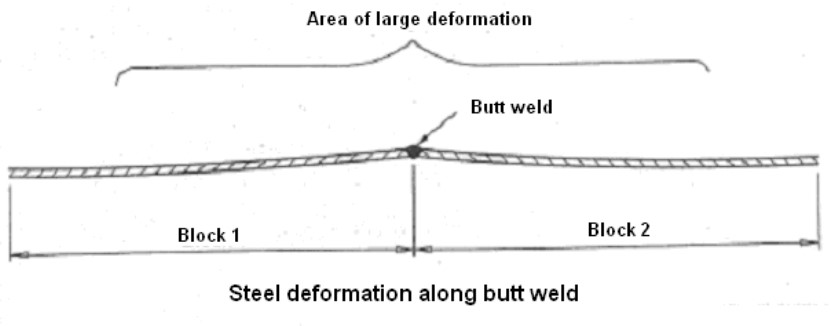
It must be measured and recorded to be taken into account during examination of flatness and definition of reference wedges.
Insulation panels should never touch the plating.
4) DEFORMATION OF CORNER AREAS (Figure 10).
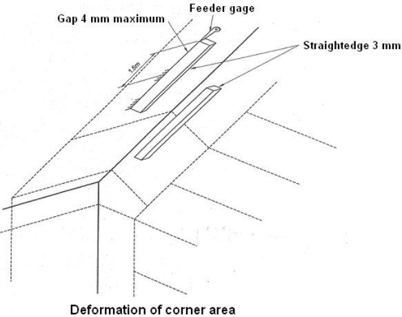
In corner areas, 2 criteria are considered:
- Flatness of the inner hull.
- Straightness of the edge.
Due to corner panels being 3,0 m and the rigidity of the angle between the two bulkheads, particular attention should be taken at prefabrication and assembly of corner blocks.
For the flatness of the corner area, the same procedure as the flat wall should be applied.
The straightness of the edges may be checked with a 3 m long straight edge with a maximum recommended gap of 4 mm on 1,5 m.
Note that an additional flatness check will be performed after marking out operations.
Inner Hull Cleanliness and Environment Conditions
Insulating panels are secured on the inner hull through epoxy mastic ropes. In order to insure proper adhesion, the inner surface must be clean.
Any oil, grease, excessive dust or dust film (vacuum cleaner is recommended, air pressure blowing does only move the dust) and rust (rust should be brushed or sanded) must be thoroughly removed.
Shop primer used to inhibit rust at sub-assembly stage and coatings applied to fabricated blocks are to be used for test of proper adhesion by epoxy mastic.
During the construction of the tanks, temperature and humidity must be controlled within specified parameters. This is important as regard to the quality of the mastic application, bonded assemblies and to minimize moisture absorption by wood used for insulation panels.
The requirements are:
- No condensation inside the tank and on inner hull during mastic patches application and other bonding operations is allowed (temperature of steel surface must be 2 or 3 °C above the dew point).
- Temperature of inner bottom should at no time be to drop below 10 °C. Curing time of mastic will be adversely affected if temperature is allowed to drop too much.
- For optimum conditions to install Cargo Containment Systems of LPG and LNGcargo containment systems, it is advisable to maintain air temperature within the tank between 15 °C and 30 °C (in particular, during adhesive application, the maximum pot life duration and adhesive open time should be determined for 30 °C).
Marking: Reference Lines
Marking out of the hull is critical as corrugations of MARK III System: Hull and Deck Components for Marine Vesselsthe MARK III system must fall in exact locations as required by design and configuration of the various faces of the tanks.
The membrane is welded to the anchoring strips on the insulating panels, which are fitted and positioned to the inner hull through the studs welded on the inner hull.
Even though a positioning tolerance is allowed for the anchoring strips (used to fasten the membrane sheets), the marking-out of the fitting elements of the insulation should be as accurate as possible to avoid excessive deviation, which could be difficult to rectify during the membrane installation.
1) BASIC ELEMENTS TO BE MARKED-OUT ON EACH BULKHEAD
The lay-out of the cryogenic liner on each bulkhead of the cargo tank is defined by designer’s drawings, which determine the final positioning of the various components (see Figure 11).
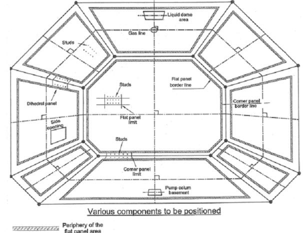
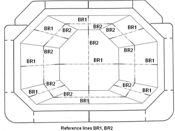
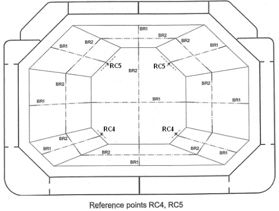
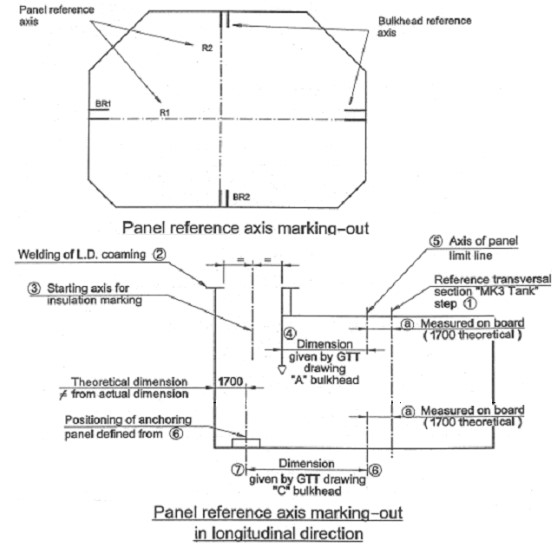
On flat panel areas, two perpendicular reference lines BR1 and BR2 (bulkhead reference axis) are to be traced. They will be used as a basis for the marking of panel limits and studs location and the marking of the periphery of the flat panels (see Figure 12).
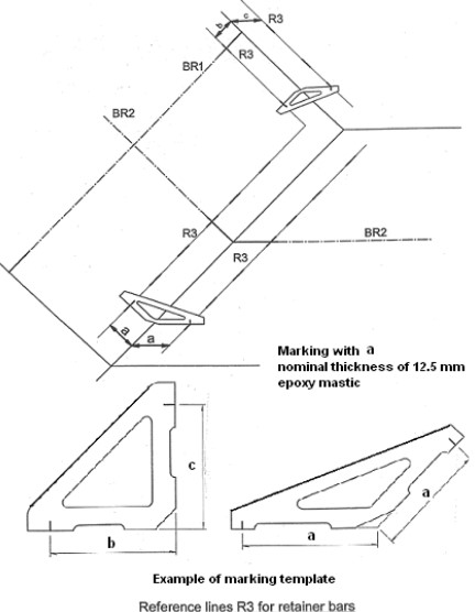
Reference line R3 will allow to position the retainer bars either at the block prefabrication stage or after completion of block erection (see Figure 13).
Reference points RC4 and RC5 will allow the cross check of the marking out (see Figure 14).
2) MARKING–OUT OF THE REFERENCE AXIS BR1 AND BR2
Because of the block fabrication and erection tolerances, the actual hold geometry cannot comply theoretically with the fundamental criteria as far as:
- perpendicularity of the corrugation axis for each bulkhead;
- continuity of the corrugation between adjacent bulkheads;
- orthogonal annulus network in three dimensions.
However, deviations are small compared to the large dimension of the tank and they can be absorbed by the installation tolerances of the membrane components if these deviations are well balanced.
For this purpose, GTT has developed a computer program based on the following:
- Definition of the actual hold.
- Determination of a theoretical mean tank of regular shape as close as possible of the actual one.
- Determination of the theoretical tank wall axis.
- Transfer of these axis on the corresponding face of the actual hold.
- Cross check of the axis above marked-out.
After measuring the tank, the dimensions are input in a computer program to calculate the actual geometrical shape of the tank. The program supplies for each bulkhead the drawing of actual geometry with the positioning of the reference axis to be transferred on board.
3) MARKING OUT OF REFERENCE LINE R3
Derived from theoretical drawing.( See Figure 13).
4) MARKING-OUT OF THE REFERENCE POINTS RC4 AND RC5
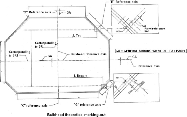
These points, which are the intersection of corrugation axis between transverse bulkhead and chamfer are defined on the bulkhead theoretical marking out drawing.
If the marking is perfect the dimensions given on the bulkhead theoretical marking out as R top and R bottom will be measured on board between the corrugation axis and the reference axis of the chamfers.
On the contrary, depending of the value of the off-set and the actual location of the longitudinal chamfer axis, one of the following solutions will be applicable:
- Acceptable without any modification.
- Modification of the longitudinal position of the chamfer axis.
- Prefabrication of special dog-legs (extreme case).
These points will be only used as a cross check means for the positioning of the basis of the reference lines and additionally to check if the corrugation axis passing by the reference R top, R bottom points RC4, RC5 are on the chamfer, at a distance given on the bulkhead theoretical marking out drawing from the longitudinal axis E (BR1).
5) MARKING OUT CROSS-CHECK ON BOARD
It is necessary to cross-check the marking out of the reference axis on board.
For this cross-check, the following procedure should be applied for each bulkhead. (See Figures 15 and 16).
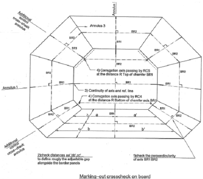
Check the perpendicularity of axis BR1, BR2 by conventional method.
Check the distance between axis BR1, BR2 and the edges in order to roughly define for the four sides of the bulkhead, the value of the adjustable gap alongside the border panels. These gaps should be similar symmetrically to axis and must fall inside the tolerance previously defined.
Check with a steel strip the continuity of the reference axis from the bulkhead to the other adjacent one, which form three orthogonal annulus.
Measurement or marking-out should not be done during movement of the ship or during ballast test. The slight deflections of the ship during this operation could induce some deviations of unknown amplitude. The measurement of the whole cargo hull to be input in the computer should be carried out in one day and if possible during stable temperature period, for example during night.
Marking-out of Panels and Stud Positions
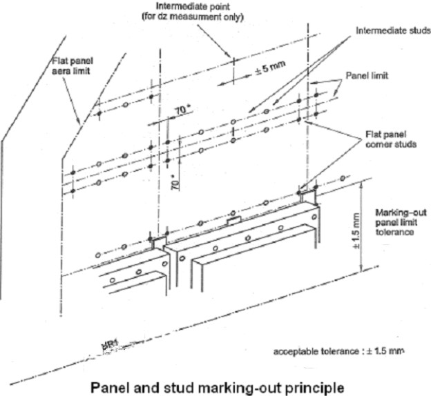
1) PANEL AND STUD MARKING-OUT PRINCIPLE
The following is to be marked-out:
- flat panel area limits;
- intermediate points on panel axis;
- flat panel corner studs;
- intermediate studs;
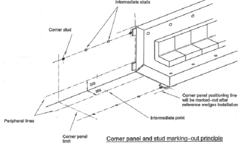
- corner panel limits, studs and peripheral line.
See Figures 17 and 18.
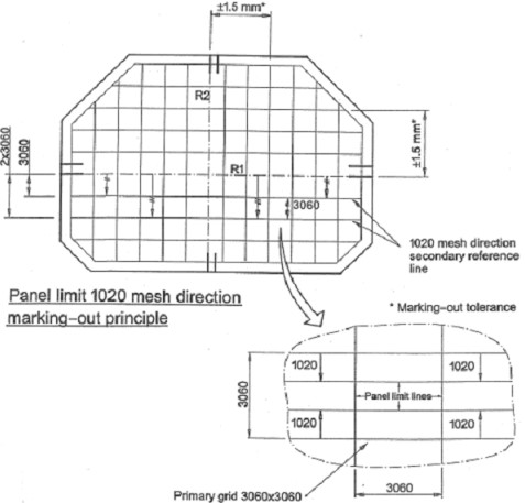
2) MARKING-OUT OF FLAT PANEL AREA LIMIT AND PANEL LIMITS
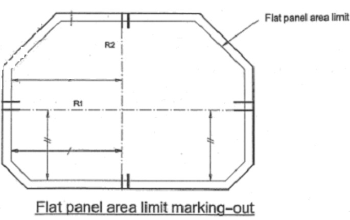
The flat panel area limit and panel limits will be used as reference for the location of studs, for the positioning of reference wedges and for positioning of panels during erection.
First, panel reference axis R1, R2 parallel to the bulkhead reference axis BR1 and BR2 will be carefully marked-out. These new axes R1, R2 will be reference lines for the flat panel and the 3 060, 1 020 mesh geometry of panel layout. Their positions according to reference axes BR1, BR2 are given on the bulkhead theoretical marking-out.
The flat panel area limit will be marked-out in reference to axis R1, R2.
The tolerance of the panel limit lines according to references line R1, R2 is +/- 1,5 mm.
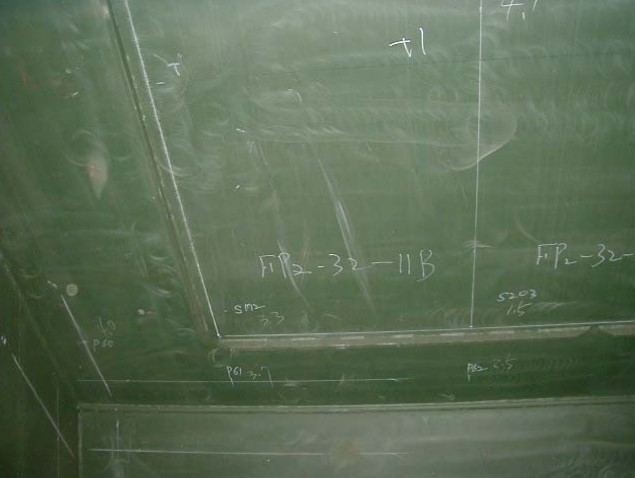
See Figure 19 through 22.
3) MARKING-OUT OF INTERMEDIATE POINTS
Intermediate points will be used for the measuring of intermediate dz value of panel and installation of the corresponding middle panel reference wedges. See Figure 23.
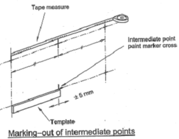
The position of these intermediate points will be measured with a tape or a template. This operation does not require a high degree of accuracy (+/- 5 mm).
4) MARKING-OUT OF STUDS
Marking-out of studs located in the corners of panels will be used after welding as reference for the positioning of intermediate studs. See Figure 24.
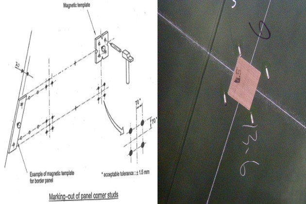
These studs, which are always located at the same distance of the panel limit lines will be clearly marked on the steel surface as they will be used as references for template: position tolerance of the centering point according to panel limit lines is +/- 1,5 mm.
5) MARKING-OUT OF INTERMEDIATE STUDS
The marking-out of these studs for standard and semi standard panels can be avoided at this stage if adequate template is used for the location and welding (refer to stud welding).
For special shape panels as border panels located on the transverse bulkhead in the upper and lower chamfer area, the intermediate studs will be marked-out with a tape according to flat panel drawing hole dimensioning.
6) MARKING-OUT OF CORNER PANEL STUDS
Corner panel limits perpendicular to edges will be marked-out afterwards, in line with corresponding flat panel limits. See Figure 25.
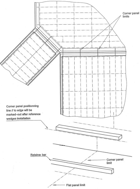
Corner panel positioning line parallel to the edge will be marked-out after reference wedges installation.
Peripheral line located at 200 mm from the edge of bulkhead will be drawn using a template.
Positioning of studs of corner panels can be carried out before reference wedge installation, just after flatness calculation.
Due to the fact that the position of the studs is linked to the thickness of the reference wedges of the corner panels, the positioning of the studs at that time will be carried out by using a template with adjustable screws set according to flatness program results.
If the stud welding sequence can be carried out in two steps: flat area, then corner panel area, the stud marking can be made at the same time as reference wedges adjustment.
Sensors in Interbarrier Spaces
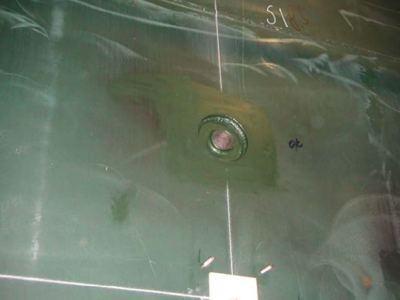
Finally, positions of sensors in interbarrier spaces are marked. See Figure 26.
Retanier Bars
Retainer bars are flat bars welded on the inner hull. They constitute, a mechanical stopper of the corner panels. See Figures 27 and 28. They are of same steel grades as the inner hull. Note retainer bars can be welded to blocks at pre-erection stage or erection stage.
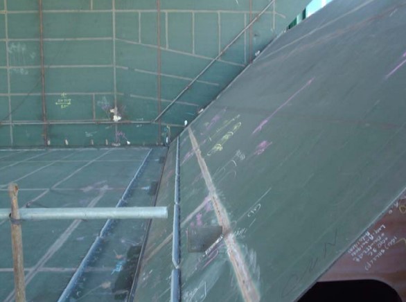
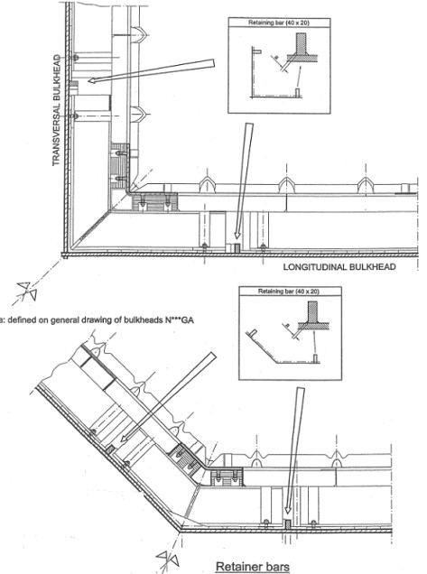
Their position with respect to the edge of the tank is well determined assuming a nominal thickness of epoxy mastic and a defined width of the corner panel. The variation of the epoxy mastic thickness can be easily absorbed by the installation tolerances.
The welds of the retainer bars can be intermittent except for the retainer bar located on the bottom face. The bottom retainer bars are used as tight gutter bars channeling the water coming from a possible leak from the ballast tanks to the forward and aft bilge wells.
The retainer bars may be welded at the block stage, only the pieces located in way of the block junction will be welded on board. A length of 1 m is not to be welded on each side of the block junction line at the prefabrication stage.
The retainer bar should not coincide with a block weld seam. Except for the bottom face, the retainer bar is interrupted in way of the seam weld zone. The extremities of the retainer bars have to be tapered.
Position and straightness tolerance is +/- 3 mm.
Determination of the Reference Surface for Insulation Lay-out
The inner hull of Independent Cargo Tankscargo tanks shows after assembly some irregularities (deformation, steps, welding overlay etc.), which do not allow the installation of the insulation in direct contact with the steel plating.
In order to accommodate with the inner hull deformation and also to fulfill the flatness requirements, the insulation will be applied on steel hull through the transition of epoxy mastic. See Figure 29.
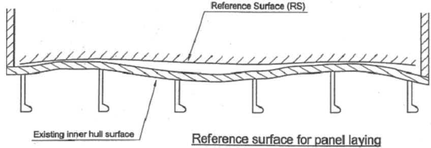
To take into account of the existing hull surface and also the flatness requirements, the insulation will be leveled according to a reference surface, which is not necessarily flat (in fact never flat). See Figure 30.
1) DETERMINATION OF THE REFERENCE SURFACE (RS)
The reference surface will be used for the installation and leveling of the insulation for flat area as well as the transverse and longitudinal dihedrals of the cargo tanks. The determination of the reference surface is carried out in several steps:
- Step 1: measurement of the existing deformation of the bulkheads (faces).
- Step 2: calculation of the reference surface (by GTT computer program).
- Step 3: preparation of the reference surface on the flat panel area.
- Step 4: leveling of the insulation in the transverse corners of the cargo tanks. See Figure 31.

2) MEASUREMENT OF EXISTING DEFORMATION OF THE BULKHEAD
The deformation of the bulkhead will be obtained by measuring, at various locations, the distance dzI between the surface of the steel and a perfect plane materialized by a laser beam.
For positioning of the measuring points for dz measurement. See Figures 32 and 33.
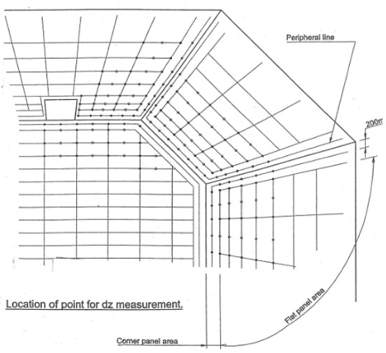
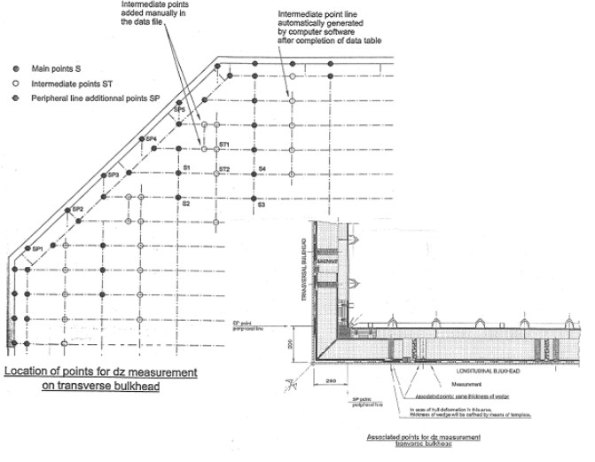
The location of the various points for the dz measurement is as follows:
- Point S: corresponding to the main reference wedges (practically location of the flat panel corner studs).
- Point ST: corresponding to the intermediate reference wedge location (practically the location of the flat panel intermediate studs).
Intermediate points are in line with the two adjacent main points.
- Point SP: in order to get a more precise information regarding the existing flatness in the vicinity of the transverse and longitudinal corners and to get a complete positioning of corner panels, additional points will be measured at the intersection of the flat panel area mesh lines with a peripheral line drawn at about 200 mm from the edges of the bulkhead.
3) CALCULATION OF THE REFERENCE SURFACE
The aim of this operation is to define, from the measurements of the hull deformations as carried out previously, an adjusted surface, not necessarily flat, which will be used as reference for the erection of the insulation.
The calculation of the reference surface, which is carried out using a computer program specially designed for this purpose, is based on the following straightness criteria. See Figures 34 and 35.
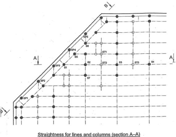
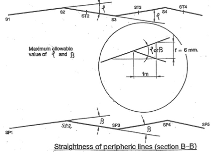
A the acceptable deformations of the reference surface will be judged according to the straightness of lines and columns drawn on the bulkhead at the reference wedge location where is the deviation between φ the lines joining 3 successive points Si.
For installation purpose of the insulation, will be taken as small as possible φ according to the overall flatness of the bulkhead under survey.
The maximum acceptable value of φ will correspond to a deflection of f = 6 mm measured over 1 m φ = 0,34°.
B the reference surface will be also defined taking into account of the straightness of the edges along two peripheral lines where β is the deviation between the lines joining 3 successive points SPi.
To ease the installation of the transverse corners, β will be as small as possible depending on the original straightness of the peripheral lines.
The maximum acceptable value of β will correspond to a deflection of f = 6 mm measured over 1 m ( β = 0,34°).
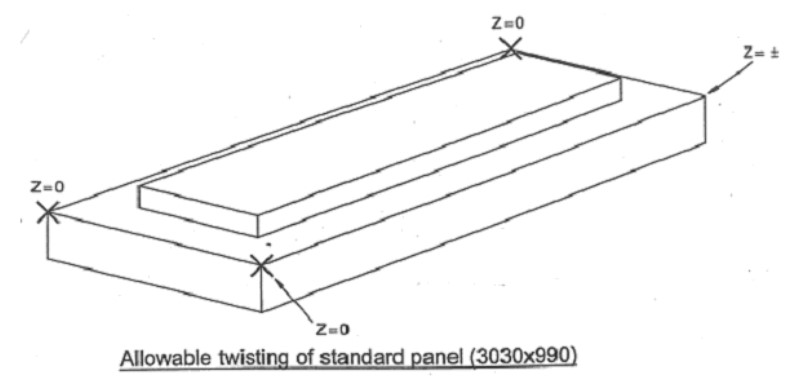
C A maximum twisting of 4 mm for a standard panel 3 × 1 m nominal will be considered. See Figure 36.
4) PRELIMINARY CALCULATION
The reference surface will be defined by the gap “g” (reference wedge thickness) calculated at each pre-set location (S, ST and SP).
For a given bulkhead, several preliminary calculations will be carried out so as to select the most appropriate straightness criteria φ and β.
For each couple ( φ , β ) a computer print is issued, which summarizes the calculation results, which include:
- Histogram showing the distribution of the gap “g” over the entire bulkhead.
- Twisting of panels: as the reference surface is not flat, the main reference wedges located at each corner of the panel are not necessarily in the same plane.
- Histogram of gaps “g” for the intermediate points.
5) RESIN ROPE ESTIMATION
Each panel bears on the inner hull through the transition of resin ropes. In order to limit the consumption of resin, various types of ropes will be used depending of the gap “g” as defined in table below.
| Various Types of Ropes | |||
|---|---|---|---|
| GAP “g” mm | TYPE | RESIN BEAD WIDTH 25 mm (Section mm2) | RESIN PATCH DIA : 60 mm (Volume cm3) |
| g < 7 | C1 | 200 | 23 |
| 7 < g < 12 | C2 | 350 | 40 |
| 12 < g < 15 | C3 | 430 | 50 |
| 15 < g < 20 | C4 | 580 | 65 |
| 20 < g < 25 | C5 | 720 | 80 |
| g > 25 | – | To be determined by test depending of “g”- | |
«Note: to absorb the various local irregularities of the steel hull such as steps between plates, overlay of welding, as also to create a draining space, a minimum gap “g” of 4 mm is observed (already input in the computer program).»
6) FINAL CALCULATIONS
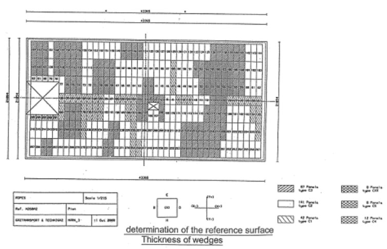
By comparing the various preliminary calculations, the most appropriate value of the straightness criteria φ and β will be selected for the bulkhead and final calculations will be run leading to the following values (see Figure 37):
- Thickness of wedges for each pre-set location.
- Distribution of the resin rope size for each individual panel of the bulkhead.
Preparation of the Reference Surface. Installation of the Reference Wedges.
The reference surface will be materialized by means of rigid wedges quick bonded at each pre-set location.
1) FLAT PANEL AREA
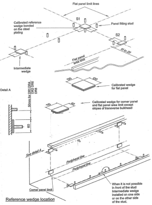
Following the drawing given by the software, the main reference wedges (S1, S2,….) will be installed at each intersection of panel limits. One wedge is common to four panels.
The intermediate wedges will be installed afterwards according to the thickness value given in the data file and a checking will be carried out to measure the alignment.
With the main reference wedges, the allowable tolerance is +/- 1,5 mm on 1,5 m. See Figure 38.
2) CORNER PANELS
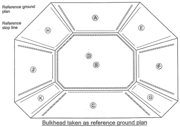
In order to insure a perfect positioning of corner panels, it is necessary to have on one side a reference ground plan and on other side a reference stop line. See Figures 39 and 40.
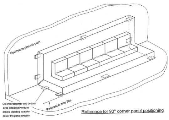
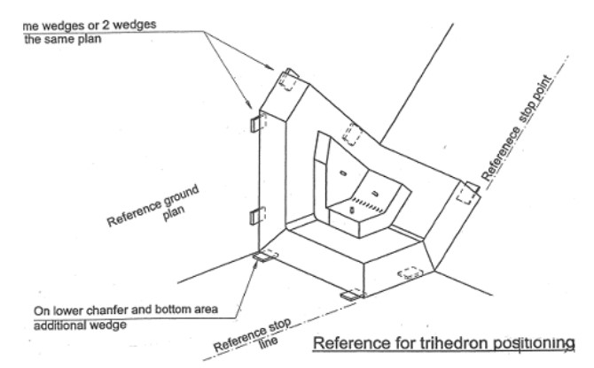
Positioning of these corner panels will be made as shown on Figure 41, due to the wide angle of the longitudinal dihedral and the small width of the corresponding corner panel leg.
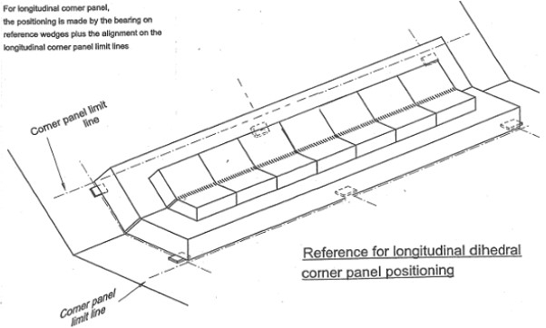
The bulkheads A, B, C, D, F, J are the reference ground plans. See Figure 42.
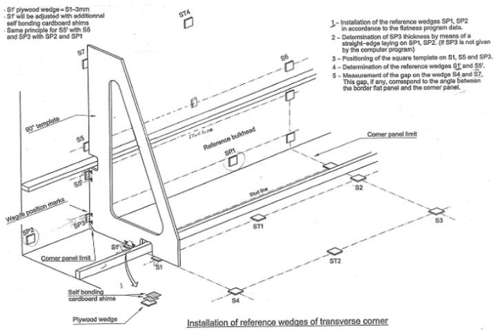
Reference wedges will be installed by means of templates designed for each angle (90°, 135°, …).
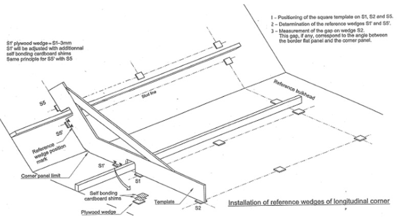
The template will be set on the flat panel area directly on reference wedges. In order to have a good adjustment of these corner panel reference wedges, the plywood wedge can be prepared thinner, -3 mm for example, than the theoretical thickness and self-bonding cardboard shims will be added. See Figures 43 and 44.
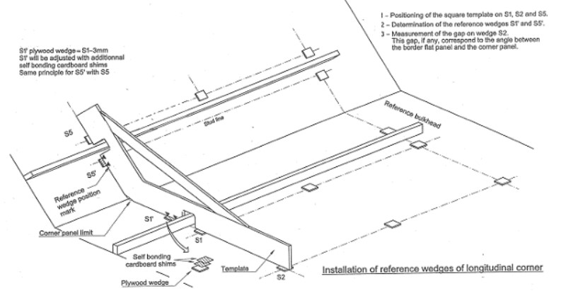
Intermediate wedges for corner panel can be installed following the same principle. See Figure 45.
3) CONTROL
After the wedge installation, a general control will be carried out on the flat panel area and corner panel area to check:
- if the wedges are in line or inside the allowable angle tolerance between panels;
- if the corner panels are in line and if the angle deviation with the flat panels is inside the allowable tolerance;
- if the intermediate wedges are inside the allowable tolerance with the adjacent main reference wedges;
- if there is no protruding point of the steel plating above the reference surface (the insulation panel should not touch the inner hull plating).
4) MARKING OF CORNER PANEL LIMIT
Once the installation of the reference wedges in corner area is done, the panel limit lines parallel to the edge can be carried out.
These lines will be used as a visual guide for all corner panel installation and a reference for the longitudinal corner panel positioning.
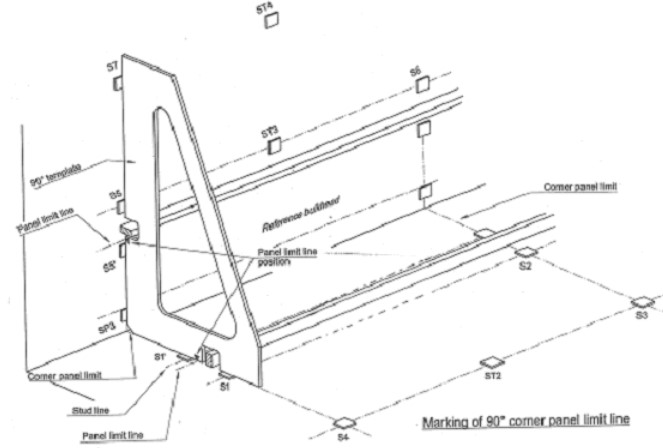
For the 90° corner panels, the marking-out can be done at the same time as the reference wedge installation. See Figure 46.
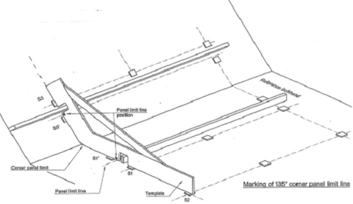
For the 135° and other longitudinal dihedral angle, a template will be used. See Figure 47.
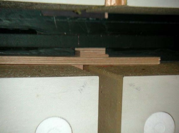
«Note: for accuracy control and in case a reference wedge dislodges and is missingtake down, the thickness of each wedge should be marked on the steel plating, so it can be replaced as needed.»
Figure 48 shows reference wedges.
Determination of the Reference Surface for the Liquid Dome
1) OPENING ADJUSTMENT PRINCIPLE
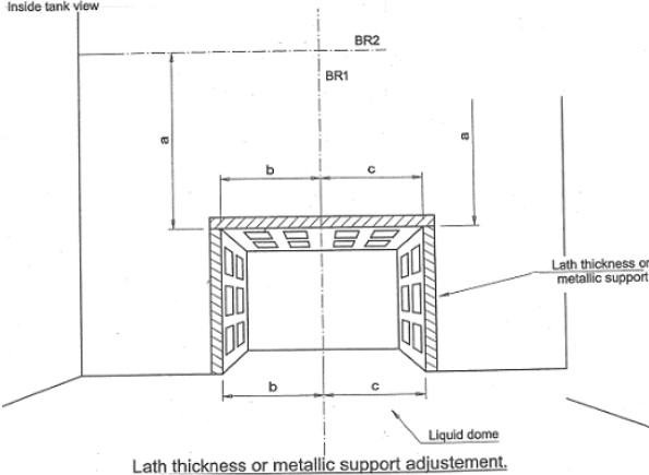
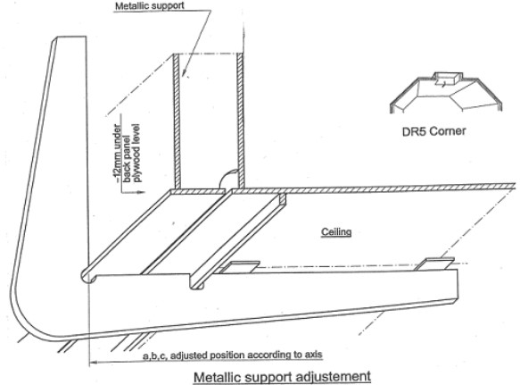
Due to protrusion of hull structure and corner radi in the dome opening as well as arrangement of hull stiffeners (not generally in phase with the insulation arrangement) it becomes necessary to adjust the opening by additional lath thickness or/and metallic support. See Figure 49.
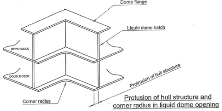
Lath thickness or/and metallic support will be installed after marking of bulkhead axis and after reference wedge installation are to be in line with the bulkhead arrangement. See Figures 50, 51 and 52.
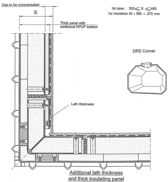
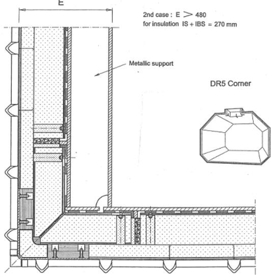
The surface of lath thickness will be at the panel back plywood level.
The surface of metallic support will be at 12 mm under the panel back plywood level to take in account the epoxy thickness under the panel.
2) INSTALLATION PROCEDURE
LATH THICKNESS INSTALLATION
If the gap to be compensated is smaller than 180 mm, lath thickness will be used in the corner of the dome and a special thick flat panel will be installed on flat area.
Lath thickness will be installed and arrested with epoxy mastic on reference wedges determined by means of templates taking the reference on the ceiling or transversal bulkhead. See Figure 53.
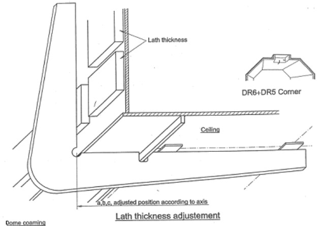
3) METALLIC SUPPORT INSTALLATION
Metallic support will be maintained in place by means of clamps, then adjusted with template, tack welded, checked again and welded. See Figure 54.
4) REFERENCE WEDGE INSTALLATION
Reference surface will be performed manually in way of the dome area.
Installed lath thickness it will be used as reference level to determine the thickness of reference wedges of flat panels by means of tight lines or templates.
When using metallic supports, wedges in corner locations will be first installed by means of templates taking reference on the ceiling or transverse bulkheads, then flat panel reference wedges will be installed following the same principle as describe above.
For dome corners, stud positioning and panel limit marking will be carried out following the same principle as inside tank corners.

