This article provides important information, schemes and formulas about Cargo Containment System of Gas Carriers.
- General
- Definitions
- Integral tanks
- Membrane tanks
- Semi-membrane tanks
- Independent tanks
- Internal insulation tanks
- Design vapour pressure
- Design temperature
- Design loads
- General
- Internal pressure
- External pressure
- Dynamic loads due to ship motions
- Sloshing loads
- Thermal loads
- Loads on supports
- Structural analysis
- Integral tanks
- Membrane tanks
- Semi-membrane tanks
- Type A independent tanks
- Type B independent tanks
- Guidelines for Fracture Mechanics Analysis
- Type C independent tanks
- Guidance for analysis
- Stiffening rings
- Supports
- Internal insulation tanks
- Allowable stresses and corrosion allowance
- Allowable stresses
- Corrosion allowance
- Supports
- Secondary barrier
- Insulation
- Materials
- Construction and testing
- Stress relieving for type C independent tanks
- Guidance formulae for acceleration components
- Stress categories
General
With regard to this article reference is made to the Unified Requirements G1 and G2 of the International Association of Classification Societies (I.A.C.S.).
In addition to the definitions in Section 1, C., the definitions given in this article apply throughout these Rules.
Definitions
Integral tanks
Integral tanks form a structural part of the ship’s hull and are influenced in the same manner and by the same loads which stress the adjacent hull structure. The “design vapour pressure” P0 as defined in “Design vapour pressure” is not normally to exceed 0,25 bar. If, however, the hull scantlings are increased accordingly, P0 may be increased to a higher value but less than 0,7 bar.
Integral tanks may be used for products provided the boiling point of the cargo is not below -10 °C. A lower temperature may be accepted by the Society subject to special consideration.
Membrane tanks
Membrane tanks are non-self-supporting tanks which consist of a thin layer (membrane) supported through insulation by the adjacent hull structure. The membrane is designed in such a way that thermal and other expansion or contraction is compensated for without undue stressing of the membrane.
The design vapour pressure P0 is not normally to exceed 0,25 bar. If, however, the hull scantlings are increased accordingly, and consideration is given, where appropriate, to the strength of the supporting insulation, P0 may be increased to a higher value but less than 0,7 bar.
The definition of membrane tanks does not exclude designs such as those in which non-metallic membranes are used or in which membranes are included or incorporated in the insulation. Such designs require, however, special consideration by the Society. In any case the thickness of the membranes should normally not exceed 10 mm.
Semi-membrane tanks
Semi-membrane tanks are non-self-supporting tanks in the loaded condition and consist of a layer, parts of which are supported through insulation by the adjacent hull structure, whereas the rounded parts of this layer connecting the above mentioned supported parts are designed also to accommodate the thermal and other expansion or contraction.
The design vapour pressure P0 is not normally to exceed 0,25 bar. If, however, the hull scantlings are increased accordingly, and consideration is given, where appropriate, to the strength of the supporting insulation, P0 may be increased to a higher value but less than 0,7 bar.
Independent tanks
Independent tanks are self-supporting; they do not form part of the ship’s hull and are not essential to the hull strength. There are three categories of independent tanks referred below.
Type A independent tanks are tanks which are designed primarily using classical ship-structural analysis procedures. Where such tanks are primarily constructed of plane surfaces (gravity tanks), the design vapour pressure P0 is to be less than 0,7 bar.
Type B independent tanks are tanks which are designed using model tests, refined analytical tools and analysis methods to determine stress levels, fatigue life and crack propagation characteristics. Where such tanks are primarily constructed of plane surfaces (gravity tanks) the design vapour pressure P0 is to be less than 0,7 bar.
Type C independent tanks (also referred to as pressure vessels) are tanks meeting pressure vessel criteria and having a design vapour pressure P0 not less than:
Where:
- σm – design primary membrane stress;
- ΔσA – allowable dynamic membrane stress (double amplitude at probability level Q=10-8);
- ΔσA – 55 N/mm2 for ferritic-perlitic, martensitic and austenitic steel;
- ΔσA – 25 N/mm2 for aluminium alloy (5083-0) (Al Mg 4,5 Mn);
- C – a characteristic tank dimension to be taken as the greatest of the following:
2 0,75∙b;
3 0,45∙ℓ;
with:
- h – height of tank (dimension in ship’s vertical direction) [m];
- b – width of tank (dimension in ship’s transverse direction) [m];
- ℓ – gth of tank (dimension in ship’s longitudinal direction) [m];
- ρr – the relative density of the cargo (ρr = 1 for fresh water) at the design temperature.
However, the Society may allocate a tank complying with the criterion of this sub-paragraph to type A or type B, dependent on the configuration of the tank and the arrangement of its supports and attachments.
If the carriage of products not covered by “Minimum requirements”Summary of Minimum Requirements for LNG and LPG tankers is intended, the relative density of which exceeds 1,0, it is to be verified that the double amplitude of the primary membrane stress Δσm created by the maximum dynamic pressure differential Δp does not exceed the allowable double amplitude of the dynamic membrane stress ΔσA as specified above, i.e.:
The dynamic pressure differential Δp is to be calculated as follows:
Where aβ1 and zβ1 are the aβ– and zβ– values giving the maximum liquid pressure (Pgd)max as defined in “Internal pressure”, aβ2 and zβ2 are the aβ– and zβ– values giving the minimum liquid pressure, see Pic. 1. For ρ see here.
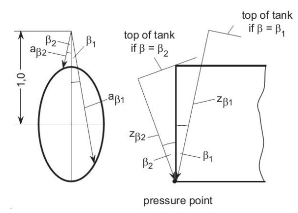
In order to evaluate the maximum pressure differential Δp, pressure differentials are to be evaluated over the full range of the acceleration ellipse.
Internal insulation tanks
Internal insulation tanks are non-self supporting and consist of thermal insulation materials which contribute to the cargo containment and are supported by the structure of the adjacent inner hull or of an independent tank. The inner surface of the insulation is exposed to the cargo.
The two categories of internal insulation tanks are:
- Type 1 tanks are tanks in which the insulation or a combination of the insulation and one or more liners function only as the primary barrier. The inner hull or an independent tank structure should function as the secondary barrier when required.
- Type 2 tanks are tanks in which the insulation or a combination of the insulation and one or more liners function as both the primary and the secondary barrier and where these barriers are clearly distinguishable.
The term “liner” means a thin, non-self-supporting, metallic, non-metallic or composite material which forms part of an internal insulation tank in order to enhance its fracture resistance or other mechanical properties. A liner differs from a membrane in that it alone is not intended to function as a liquid barrier.
Internal insulation tanks are to be of suitable materials enabling the cargo containment system to be designed using model tests and refined analytical methods as required in “Internal insulation tanks”.
The design vapour pressure P0 shall not normally exceed 0,25 bar. If, however, the cargo containment system is designed for a higher vapour pressure, P0 may be increased to such higher value, but not exceeding 0,7 bar if the internal insulation tanks are supported by the inner hull structure. However, a design vapour pressure of more than 0,7 bar may be accepted by the Society provided the internal insulation tanks are supported by suitable independent tank structures.
Design vapour pressure
The design vapour pressure P0 is the maximum gauge pressure at the top of the tank which has been used in the design of the tank.
For cargo tanks where there is no temperature control and where the pressure of the cargo is dictated only by the ambient temperature, P0 is not to be less than the gauge vapour pressure of the cargo at a temperature of 45 °C. However, lesser values of this temperature may be accepted by the Society for ships operating in restricted areas or on voyages of restricted duration and account may be taken in such cases of any insulation of the tanks. Conversely, higher values of this temperature may be required for ships permanently operating in areas of high ambient temperature.
In all cases, including information above, P0 is not to be less than MARVS.
Subject to special consideration by the Society and to the limitations given in “Integral tanks” to “Internal insulation tanks” for the various tank types, a vapour pressure higher than P0 may be accepted in harbour conditions, where dynamic loads are reduced.
Higher vapour pressures in harbour conditions are to be specified in the operating instructions for the ship’s management.
Design temperature
The design temperature for selection of materials is the minimum temperature at which cargo may be loaded or transported in the cargo tanks. Provisions to the satisfaction of the Society are to be made that the tank or cargo temperature cannot be lowered below the design temperature.
Design loads
General
Tanks together with their supports and other fixtures are to be designed taking into account proper combinations of the various loads listed here after:
- Internal pressure;
- External pressure;
- Dynamic loads due to the motion of the ship;
- Thermal loads;
- Sloshing loads;
- Loads corresponding to ship deflection;
- Tank and cargo weight with the corresponding reactions in way of supports;
- Insulation weight;
- Loads in way of towers and other attachments.
The extent to which these loads are to be considered depends on the type of tank, and is more fully detailed in the following paragraphs.
Account is to be taken of the loads corresponding to the pressure test referred to in “Construction and testing”. Account is to be taken of an increase of vapour pressure in harbour conditions referred to in “Design vapour pressure”.
The tanks are to be designed for the most unfavourable static heel angle within the range 0° to 30° without exceeding allowable stresses given in “Allowable stresses”.
Internal pressure
The internal pressure Pi in bar gauge resulting from the design vapour pressure P0 and the liquid pressure Pgd defined below, but not including effects of liquid sloshing, is to be calculated as follows:
Equivalent calculation procedures may be applied.
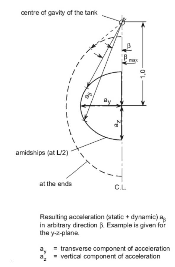
The internal liquid pressures are those created by the resulting acceleration of the centre of gravity of the cargo due to the motions of the ship referred to in “Dynamic loads due to ship motions”. The value of the internal liquid pressure Pgd resulting from combined effects of gravity and dynamical accelerations is to be calculated as follows:
Where:
- aβ – dimensionless acceleration (i.e. relative to the acceleration of gravity), resulting from gravitational and dynamical loads, in an arbitrary direction β (see Pic. 2).
- zβ – largest liquid height [m] above the point where the pressure is to be determined measured from the tank shell in the direction (see Pic. 2). Tank domes considered to be part of the accepted total tank volume are to be taken into account when determining zβ unless the total volume of tank domes Vd does not exceed the following value:
Where:
- Vt – tank volume without any domes;
- FL – filling limit according to Section 15;
- ρ – maximum density of the cargo [kg/m3] at the design temperature.
Guidance values for the density P are given in column (k) of the list of cargoes in “Minimum requirements”Summary of Minimum Requirements for LNG and LPG tankers.
The direction which gives the maximum value (Pgd)max of Pgd is to be considered. Where acceleration components in three directions need to be considered, an ellipsoid is to be used instead of the ellipse in Pic. 2. The above formula applies only to full tanks.
In general, it is sufficient to determine the liquid pressure Pgd for the ship’s cross section (y-z-plane) and for the ship’s longitudinal section (z-x-plane) and to determine the scantlings for the maximum pressure so obtained.
External pressure
External design pressure loads are to be based on the difference between the minimum internal pressure (maximum vacuum) and the maximum external pressure to which any portion of the tank may be subjected simultaneously.
Dynamic loads due to ship motions
The determination of dynamic loads is to take account of the long term distribution of ship motions, including the effects of surge, sway, heave, roll, pitch and yaw on irregular seas which the ship will experience during her operation life (normally taken to correspond to 108 wave encounters). Account may be taken of reduction in dynamic loads due to necessary speed reduction and variation of heading when this consideration has also formed part of the hull strength assessment.
For design against plastic deformation and buckling the dynamic loads are to be taken as the most probable largest loads the ship will encounter during her operating life (normally taken to correspond to a probability level of 10-8). Guidance formulae for acceleration components are given in “Guidance formulae for acceleration components”.
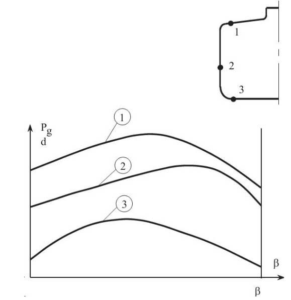
When design against fatigue is to be considered, the dynamic spectrum is to be determined by long term distribution calculation based on the operating life of the ship (normally taken to correspond to 10 wave encounters). If simplified dynamic loading spectra are used for the estimation of the fatigue life, these are to be specially considered by the Society. An example is given in Pic. 4.
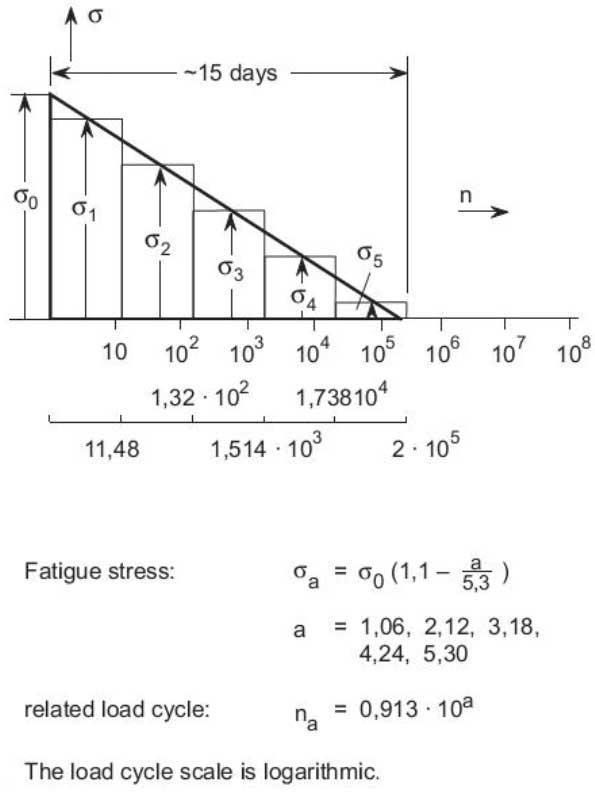
In order to practically apply crack propagation estimates, simplified load distribution over a period of 15 days may be used. Such distributions may be obtained as indicated in Pic. 5.

Ships for restricted service may be given special consideration.
The accelerations acting on tanks are estimated at their centre of gravity and include the following components:
- Vertical Acceleration: Motion accelerations of heave, pitch and, possibly roll (normal to the ship base).
- Transverse Acceleration: Motion accelerations of sway, yaw and roll, and gravity component of roll.
- Longitudinal Acceleration: Motion acceleration of surge and pitch, and gravity component of pitch.
For the direct calculation of dynamic loads computer programs of BKI may be used.
Sloshing loads
When partial filling is contemplated, the risk of significant loads due to sloshing induced by any of the ship motions referred in list above is to be considered. When risk of significant sloshing induced loads is found to be present, special tests and calculations will be required.
Thermal loads
Transient thermal loads during cooling down periods are to be considered for tanks intended for cargo temperatures below -55 °C. Stationary thermal loads are to be considered for tanks where design supporting arrangement and operating temperature may give rise to significant thermal stresses.
Loads on supports
The loads on supports are covered by “Thermal loads”.
Structural analysis
Integral tanks
The structural analysis of integral tanks is to be in accordance with Rules for Hull, Volume II, Section 24. The tank boundary scantlings are to meet at least the requirements for deep tanks taking into account the internal pressure as indicated in “Internal pressure” but the resulting scantlings are not to be less than normally required by the Society.
Membrane tanks
For membrane tanks, the effects of all static and dynamic loads are to be considered to determine the suitability of the membrane and of the associated insulation with respect to plastic deformation and fatigue.
Before approval is given, a model of both the primary and secondary barriers, including corners and joints, is normally to be tested to verify that they will withstand the expected combined strains due to static, dynamic and thermal loads. Test conditions are to represent the most extreme service conditions the cargo containment system will see in its life. Material tests are to ensure that ageing is not liable to prevent the materials from carrying out their intended function.
For the purpose of the test referred above, a complete analysis of the particular motions, accelerations and response of ships and cargo containment systems is to be performed, unless these data are available from similar ships.
Special attention is to be paid to the possible collapse of the membrane due to an overpressure in the interbarrier space, to a possible vacuum in the cargo tank, to the sloshing effects and to hull vibration effects.
The structural analysis of the hull is to be in accordance with Rules for Hull, Volume II, Section 24, taking into account the internal pressure as indicated in “Internal pressure”. Special attention, however, is to be paid to deflections of the hull and their compatibility with the membrane and associated insulation. Inner hull plating thickness is to meet at least the requirements for deep tanks taking into account the internal pressure as indicated in “Internal pressure”. The allowable stress for the membrane, membrane supporting material and insulation is to be determined in each particular case.
Semi-membrane tanks
A structural analysis is to be performed in accordance with the requirements for membrane tanks or independent tanks as appropriate, taking into account the internal pressure as indicated in “Internal pressure”.
Type A independent tanks
A structural analysis is to be performed in accordance with Rules for Hull, Volume II, “Mechanical ventilation”Mechanical Ventilation in The Cargo Area on Liquefied gas tankers, taking into account the internal pressure as indicated in “Internal pressure”. The cargo tank plating thickness is to meet at least the requirements for deep tanks taking into account the internal pressure as indicated in “Internal pressure” and any corrosion allowance required by “Corrosion allowance”.
For parts, such as structure in way of supports, not otherwise covered by the Rules, stresses are to be determined by direct calculation, taking into account the loads referred to in “Design loads” as far as applicable, and the ship deflection in way of supports.
Type B independent tanks
For tanks of this type the following applies:
1 The effects of all dynamic and static loads are to be used to determine the suitability of the structure with respect to:
- plastic deformation;
- buckling;
- fatigue failure;
- crack propagation.
Statistical wave load analysis in accordance with “Dynamic loads due to ship motions” finite element analysis or similar methods and fracture mechanics analysis or an equivalent approach, are to be carried out.
2 A three-dimensional analysis is to be carried out to evaluate the stress levels contributed by the ship’s hull. The model for this analysis is to include the cargo tank with its supporting and keying system as well as a reasonable part of the hull.
3 A complete analysis of the particular ship accelerations and motions in irregular waves and of the response of the ship and its cargo tanks to these forces and motions is to be performed unless these data are available from similar ships.
4 A buckling analysis is to consider the maximum construction tolerances.
5 Where deemed necessary by the Society, model tests may be required to determine stress concentration factors and fatigue life of structural elements.
6 The cumulative effect of the fatigue load is to comply with the following formula:
Where:
- n – number of stress cycles at each stress level during the life of the ship (see Pic. 3 and 4).
- Ni – number of cycles to fracture for the respective stress level according to the Wohler (S-N) curve.
- Nj – number of cycles to fracture for the fatigue loads due to loading and unloading.
- Cw – is to be less than or equal to 0,5 except that the Society may give special consideration to the use of a value greater than 0,5 but not greater than 1,0, dependent on the test procedure and data used to establish the Wöhler (S-N) curve.
Guidelines for Fracture Mechanics Analysis
Fracture mechanics analysis shall consider propagation rates in parent material, weld metal and heat-affected zone.
The fracture mechanical properties are to be documented for the various thicknesses of parent material and weld metal alike, possibly by experiment according to ASTM E 399 – 70 T. It is to be determined to which length an assumed through thickness crack will grow to under dynamic loading.
The calculation is to be based on a stress spectrum as stipulated under “Dynamic loads due to ship motions”. The initial length of the existing crack is to be taken equal to the minimum flow size that can be detected by means of a monitoring system (e.g., gas detectors), however, not less than the plate thickness.
Type C independent tanks
The pressure vessels of independent tanks are to be calculated as follows:
- The thickness and form of pressure containing parts of pressure vessels under internal pressure, including flanges are to be determined according to a standard acceptable to the Society. These calculations in all cases are to be based on generally accepted pressure vessels design theory. Openings in pressure containing parts of pressure vessels are to be reinforced in accordance with a standard acceptable to the Society. See here to Rules for Machinery Installations, Volume III, Section 8.
- The design liquid pressure defined in “Internal pressure” is to be taken into account in the above calculations.
- The welded joint efficiency factor to be used in the calculation according №1 of this list is to be 0,95 when the inspection and the non-destructive testing referred here are carried out. This figure may be increased up to 1,0 when account is taken of other considerations, such as the material used, type of joints, welding procedure and type of loading. For process pressure vessels the Society may accept partial non-destructive examinations, but not less than those depending on such factors as the material used, the design temperature, the nil ductility transition temperature of the material as fabricated, the type of joint and welding procedure, but in this case an efficiency factor of not more than 0,85 is to be adopted. For special materials, the above mentioned factors are to be reduced depending on the specified mechanical properties of the welded joint.
Buckling criteria are to be as follows:
- The thickness and form of pressure vessels subject to external pressure and other loads causing compressive stresses are to be to a standard acceptable to the Society. These calculations in all cases are to be based on generally accepted pressure vessel buckling theory and are to adequately account for the difference in theoretical and actual buckling stress as a result of plate edge misalignment, ovality and deviation from true circular form over a specified arc or chord length.
- The design external pressure Pe used for verifying the buckling of the pressure vessels is not to be less than that given by the following formula:
Where:
- P1 = setting value of vacuum relief valves. For vessels not fitted with vacuum relief valves P1 is to be specially considered, but is not in general be taken as less than 0,25 bar.
- P2 = the set pressure of the pressure relief valves for completely closed spaces containing pressure vessels or parts of pressure vessels; elsewhere, P2=0.
- P3 = compressive actions in the shell due to the weight and contraction of insulation, weight of shell, including corrosion allowance, and other miscellaneous external pressure loads to which the pressure vessel may be subjected. These include, but are not limited to, weight of domes, weight of towers and piping, effect of product in the partially filled condition, accelerations and hull deflection. In addition the local effect of external or internal pressure or both is to be taken into account.
- P4 = external pressure due to head of water for pressure vessels or part of pressure vessels on exposed decks; elsewhere P4=0. (See also Rules for Hull ( Part 1, Vol. II) Sec. 4).
Stress analysis in respect of static and dynamic loads is to be performed as follows:
- Pressure vessel scantlings are to be determined in accordance with lists above.
- Calculations of the loads and stresses in way of the supports and the shell attachment of the support are to be made. Loads referred to in “Design loads” are to be used, as applicable. The permissible stresses in the shell and the stiffening rings in way of supports may be determined according to formula below. In special cases a fatigue analysis may be required by the Society.
- If required by the Society, secondary stresses and thermal stresses are to be specially considered.
The equivalent stress in the stiffening rings in way of supports shall not exceed one of the following values:
- σn – normal stress due to normal forces;
- σb – bending stress;
- j – shear stress;
- Re, Rm see here.
Guidance for analysis
Stiffening rings
The stiffening ring may be considered as a circumferential beam formed by web, face plate, doubler plate, if any, and associated shell plating. The effective width of the associated plating may be taken as:
1 For cylindrical shells:
on each side of the web.
Where:
- R = mean radius of the cylindrical shell in [mm];
- t = shell thickness [mm].
A doubler plate, if any, may be included within that distance.
2 For longitudinal bulkheads (in the case of lobe tanks): the effective width may be determined according to Rules for Hull, Volume II, Section 3, E. The following value on each side of the web may be taken as a guidance value:
- bm – 20·tb;
- tb – bulkhead thickness.
The stiffening ring shall be loaded with circumferential forces, on each side of the ring, due to the shear stress, determined by the bi-dimensional shear flow theory from the shear forces of the tank.
If finite element calculation methods are applied, assumption for calculations are to be specially agreed with BKI.
The buckling strength of the stiffening rings is to be examined in accordance with the requirements of Rules for Hull, Volume II, Section 3, F.
Supports
The following factors shall be taken into account:
1 Elasticity of support material (intermediate layer of wood or similar material).
2 Change in contact surface between tank and support for the different load cases, and of the relevant reactions, due to:
- thermal shrinkage of tank;
- elastic deformations of tank and support material.
The final distribution of the reaction forces at the supports shall not show any tensile forces.
For pressure vessels, the thickness calculated according to this or the thickness required by this plus the corrosion allowance, if any, is to be considered as a minimum without any negative tolerance.
For pressure vessels, the minimum thickness of shell and heads including corrosion allowance, after forming, is not to be less than 5 mm for carbon-manganese steels and nickel steels, 3 mm for austenitic steels or 7 mm for aluminium alloys.
The calculation procedure of pressure vessels is given in Rules for Machinery Installations (Part 1, Vol.III) Sec. 8.
Internal insulation tanks
The effects of all static and dynamic loads are to be considered to determine the suitability of the tank with respect to:
- fatigue failure;
- crack propagation from both free and supported surfaces;
- adhesive and cohesive strength;
- compressive, tensile and shear strength.
Statistical wave load analysis in accordance with “Dynamic loads due to ship motions”, finite element analysis or similar methods and fracture mechanics analysis or an equivalent approach are to be carried out.
Special attention is to be given to crack resistance and to deflections of the inner hull or independent tank structure and their compatibility with the insulation materials. A three-dimensional structural analysis is to be carried out to the satisfaction of the Society. This analysis is to evaluate the stress levels and deformations contributed either by the inner hull or by the independent tank structure or both and is also to take into account the internal pressure as indicated in “Internal pressure”.
Where water ballast spaces are adjacent to the inner hull forming the supporting structure of the internal insulation tank, the analysis is to take account of the dynamic loads caused by water ballast under the influence of ship motions.
The allowable stresses and associated deflections for the internal insulation tank and the inner hull structure or independent tank structure are to be determined in each particular case.
Thicknesses of plating of the inner hull or of an independent tank are to at least comply with the requirements of Rules for Hull, Volume II, Sections 12 and/or 24, taking into account the internal pressure as indicated in “Internal pressure”. Tanks constructed of plane surfaces are at least to comply with the requirements for tank structures given in Rules for Hull, Volume II, Section 12.
A complete analysis of the response of ship, cargo and any ballast to accelerations and motions in irregular waves of the particular ship is to be performed to the satisfaction of the Society unless such analysis is available for a similar ship.
In order to confirm the design principles, prototype testing of composite models including structural elements is to be carried out under combined effects of static, dynamic and thermal loads.
Test conditions are to represent the most extreme service conditions the cargo containment system will be exposed to during the lifetime of the ship, including thermal cycles. For this purpose, 400 thermal cycles are considered to be a minimum, based upon 19 round voyages per year; where more than 19 round voyages per year are expected, a higher number of thermal cycles will be required. These 400 thermal cycles may be divided into 20 full cycles (cargo temperature to 45 °C) and 380 partial cycles (cargo temperature to that temperature expected to be reached in the ballast voyage).
Models are to be representative of the actual construction including corners, joints, pump mounts, piping penetrations and other critical areas, and should take into account variations in:
- tank material properties;
- workmanship and quality control.
Combined tension and fatigue tests are to be carried out to evaluate crack behavior of the insulation material in the case where a through crack develops in the inner hull or independent tank structure. In these tests, where applicable, the crack area is to be subjected to the maximum hydrostatic pressure of the ballast water.
The effects of fatigue loading are to be determined in accordance with “Type B independent tanks” or by an equivalent method.
For internal insulation tanks, repair procedures are to be developed during the prototype testing programme for both the insulation material and the inner hull or the independent tank structure.
Allowable stresses and corrosion allowance
Allowable stresses
For integral tanks, allowable stresses are normally those given for the hull structure in Rules for Hull, Volume II, Section 24. For membrane tanks, reference is made to the requirements of this.
For type A independent tanks, primarily constructed of plane surfaces the stresses (equivalent stresses) for primary and secondary members (web frames, stringers, girders, stiffeners) when calculated by classical analysis procedures are not to exceed the lower of Rm/2,66 or Re/1,33 for carbon manganese steels and aluminium alloys, where Rm and Re are defined below.
However, if detailed calculations are carried out for the primary members, the equivalent stress, σc as defined in this formula may be increased over that indicated above to a stress acceptable to the Society; calculations have to take into account the effects of bending, shear, axial and torsional deformation as well as the hull/cargo tank interaction forces due to the deflection of the double bottom and cargo tank bottoms.
For type B independent tanks, primarily constructed of bodies of revolution, the stresses are not to exceed the following allowable values:
- σm < f;
- σL < 1,5 f;
- σb < 1,5 F;
- σL + σb < 1,5 F;
- σm + σb < 1,5 F;
- σm = equivalent primary general membrane stress;
- σL = equivalent primary local membrane stress;
- σb = equivalent primary bending stress;
- f = the lesser of func {R_m over A} or func {R_e over B};
- F = the lesser of func {R_m over C} or func {R_e over D}.
With Rm and Re as defined in this formula. With regard to the stresses σm, σL an categories in “Stress categories”.
The values of A, B, C and D are to be shown on the International Certificate of Fitness for the Carriage of Liquefied Gases in Bulk provided for in Section 1, D., and are to have at least the following minimum values (Table 1).
| Table 1. Minimum values for A, B, C and D | |||
|---|---|---|---|
| Nickel steels and carbon manganese steels | Austenitic steels | Aluminium alloys | |
| A | 3,0 | 3,5 | 4,0 |
| B | 2,0 | 1,6 | 1,5 |
| C | 3,0 | 3,0 | 3,0 |
| D | 1,5 | 1,5 | 1,5 |
For ships trading to the territorial waters of the United States of America, the relevant requirements of the U.S. Coast Guard given in Subpart C of the Federal Register, Vol. 44, No. 87, § 154.447 should be observed.
For type B independent tanks, primarily constructed of plane surfaces, the equivalent stresses σc in primary members (web frames, stringers, girders) are not to exceed the lower of the values resulting from Table 2.
| Table 2. Maximum values for equivalent stresses σc | ||
|---|---|---|
| Material | ||
| C-Mn steels and Ni-Steels | 0,75 | 0,5 |
| Austenitic steels | 0,80 | 0,4 |
| Aluminium alloy | 0,75 | 0,35 |
Furthermore, the Society may require compliance with additional or other stress criteria.
For type C independent tanks, the maximum allowable membrane stress to be used in the calculation according to “Type C independent tanks” is to be the lower of:
Where:
- Rm and Re are as defined below.
The values of A and B are to be shown on the International Certificate of Fitness for the Carriage of Liquefied Gases in Bulk and are to have at least the minimum values indicated in Table 1.
For the purpose of information above the following apply:
- Re = specified minimum yield stress in [N/mm2] at room temperature. If the stress-strain curve does not show a defined yield stress, the 0,2 % proof stress applies.
- Rm = specified minimum tensile strength in [N/mm2] at room temperature. For welded connections in aluminium alloys, the respective values of Re and Rm in annealed conditions are to be used.
The above properties are to correspond to the minimum specified mechanical properties of the material, including the weld metal in the as fabricated condition. Subject to special consideration by the Society account may be taken of enhanced yield stress and tensile strength at low temperature. The temperature on which the material properties are based are to be shown on the International Certificate of Fitness for the Carriage of Liquefied Gases in Bulk.
The equivalent stress fc (von Mises, Huber) is to be determined by:
Where:
- σx – total normal stress in x-direction;
- σy – total normal stress in y-direction;
- τxy – total shear stress in x-y-plane.
When the static and dynamic stresses are calculated separately and unless other methods of calculation are justified, the total stresses are to be calculated according to:
Where:
- σx st, σy st and τxy st are static stresses.
- σxdyn, σydyn and τxydyn are dynamic stresses all determined separately from acceleration components and hull strain components due to deflection and torsion.
For internal insulation tanks, reference is made to the requirements of “Internal insulation tanks”.
Allowable stresses for materials other than those covered by “Materials of construction natural gas tanks”Gas tank construction are to be subject to approval by the Society in each case. Stresses may be further limited by fatigue analysis, crack propagation analysis and buckling criteria.
Corrosion allowance
No corrosion allowance is generally required in addition to the thickness resulting from the structural analysis. However, where there is no environmental control around the cargo tank, such as inerting, or where the cargo is of a corrosive nature, the Society may require a suitable corrosion allowance.
For pressure vessels no corrosion allowance is generally required if the contents of the pressure vessel are non-corrosive and the external surface is protected by inert atmosphere or by an appropriate insulation with an approved vapour barrier. Paint or other thin coatings will not be credited as protection. Where special alloys are used with acceptable corrosion resistance, no corrosion allowance is required. If the above conditions are not satisfied, the scantlings calculated according to “Type C independent tanks” are to be increased as appropriate.
Supports
Cargo tanks are to be supported by the hull in a manner which will prevent bodily movement of the tank under static and dynamic loads while allowing contraction and expansion of the tank under temperature variations and hull deflections without undue stressing of the tank and of the hull.
The tanks with supports are also to be designed for a static angle of heel of 30° without exceeding allowable stresses given in “Allowable stresses”.
The supports are to be calculated for the most probable largest resulting acceleration, taking into account rotational as well as translational effects. This acceleration in a given direction may be determined as shown in Pic. 2. The half axes of the “Acceleration Ellipse” are to be determined according to “Dynamic loads due to ship motions”.
Suitable supports are to be provided to withstand a collision force acting on the tank corresponding to 0,5 g in the forward direction and 0,25 g in the aft direction without deformation likely to endanger the tank structure.
The loads mentioned above need not be combined with each other or with wave induced loads. For independent tanks and, where appropriate, for membrane and semi-membrane tanks, provisions are to be made to key the tanks against the rotational effects referred above.
Anti flotation arrangements are to be provided for independent tanks. The anti-flotation arrangements are to be suitable to withstand an upward force caused by an empty tank in a hold space flooded to the summer load draught of the ship, without plastic deformation likely to endanger the hull structure.
Secondary barrier
Where the cargo temperature at atmospheric pressure is below -10 °C, a secondary barrier is to be provided when required by this to act as a temporary containment for any envisaged leakage of liquid cargo through the primary barrier.
Where the cargo temperature at atmospheric pressure is not below -55 °C, the hull structure may act as a secondary barrier. In such a case:
- the hull material is to be suitable for the cargo temperature at atmospheric pressure as required by “Materials”;
- and the design is to be such that this temperature will not result in unacceptable hull stresses.
Secondary barriers in relation to tank types are to be provided in accordance with Table 3. For tanks which differ from the basic tank types as defined in “Definitions”, the secondary barrier requirements are to be decided by the Society in each case.
The secondary barrier is to be designed so that:
- it is capable of containing any envisaged leakage of liquid cargo for a period of 15 days, unless different requirements apply for particular voyages, taking into account the load spectrum referred here;
- it will prevent lowering of the temperature of the ship structure to an unsafe level in the case of leakage of the primary barrier as indicated in “Insulation”;
- and the mechanism of failure for the primary barrier does not also cause the failure of the secondary barrier and vice-versa.
The secondary barrier is to fulfill its functions at a static angle of heel of 30°.
Where a partial secondary barrier is required, its extent is to be determined on the basis of cargo leakage corresponding to the extent of failure resulting from load spectrum referred here after the initial detection of a primary barrier leak. Due account may be taken of liquid evaporation, rate of leakage, pumping capacity and other relevant factors. In all cases, however, the inner bottom adjacent to cargo tanks is to be protected against liquid cargo.
| Table 3. Secondary barriers in relation to tank types | ||||
|---|---|---|---|---|
| Cargo temperature at atmospheric pressure | -10 °C and above | Below -10 °C down to -55 °C | Below -55 °C | |
| Basic tank type | No secondary barrier required | Hull may act as secondary barrier | Separate secondary barrier where required | |
| Integral | Tank type not normally allowed A complete secondary barrier will normally be required if cargoes with a temperature at atmospheric pressure below –10 °C are permitted in accordance with “Integral tanks”.x | |||
| Semi-membrane | Complete secondary barrier | |||
| Membrane | Complete secondary barrier In the case of semi-membrane tanks which comply in all respects with the requirements applicable to independent tanks type B, except for the manner of support, the Society may, after special consideration, accept a partial secondary barrierx | |||
| Independent | Type A | Complete secondary barrier | ||
| Type B | Partial secondary barrier | |||
| Type C | No secondary barrier required | |||
| Internal insulation | Type 1 | Complete secondary barrier | ||
| Type 2 | Complete secondary barrier is incorpo | |||
Clear of the partial secondary barrier, provision such as a spray shield is to be made to deflect any liquid cargo down into the space between the primary and secondary barriers and to keep the temperature of the hull structure to a safe level.
The secondary barrier is to be capable of being periodically checked for its effectiveness, by means of a pressure vacuum test, a visual inspection or another suitable method acceptable to the Society. The method is to be submitted to the Society for approval.
Insulation
Where cargo is carried at a temperature below -10 °C suitable insulation is to be provided to ensure that the temperature of the hull structure does not fall below the minimum allowable design temperature given in “Materials of construction”Materials of construction LNG and LPG tanks for the grade of steel concerned, as detailed in “Materials”, when the cargo tanks are at their design temperature and the ambient temperatures are 5 °C for air and 0 °C for sea water. These conditions may generally be used for world-wide service. However, higher values of the ambient temperatures may be accepted by the Society for ships operated in restricted areas.
Conversely, lesser values of the ambient temperatures may be fixed by the Society for ships trading occasionally or regularly to areas in latitudes where such lower temperatures are expected during the winter months. The ambient temperatures used in the design are to be shown on the International Certificate of Fitness for the Carriage of Liquefied Gases in Bulk.
Where a complete or partial secondary barrier is required, calculations are to be made with the assumptions in paragraphs above to check that the temperature of the hull structure does not fall below the minimum allowable design temperature given for the concerned grade of steel in “Materials of construction”Materials of construction LNG and LPG tanks as detailed in “Materials”. The complete or partial secondary barrier is to be assumed to be at the cargo temperature at atmospheric pressure.
Calculations are to be made assuming still air and still water no credit is to be given for means of heating. In the case referred above, the cooling effect of the rising boil-off vapour from the leaked cargo is to be considered in the heat transmission studies. For structural members connecting inner and outer hulls, the mean temperature may be taken for determining the steel grade.
In all cases referred above and for ambient temperature conditions of 5 °C for air and 0 °C for sea water approved means of heating transverse hull structural material may be used to ensure that the temperatures of this material do not fall below the minimum allowable values.
If lower ambient temperatures are specified, approved means of heating may also be used for longitudinal hull structural material, provided this material remains suitable for the temperature conditions of 5 °C for air and 0 °C for sea water without heating. Such means of heating are to comply with the following requirements:
- Sufficient heat is to be available to maintain the hull structure above the minimum allowable temperature in the conditions referred above;
- The heating system is to be arranged so that, in the event of a failure in any part of the system, stand-by heating can be maintained equal to not less than 100 % of the theoretical heat load;
- The heating system is to be considered as an essential auxiliary;
- The design and construction of the heating system is to be to the satisfaction of the Society.
In determining the insulation thickness, due regard is to be paid to the amount of acceptable boil-off in association with the reliquefaction plant on board, main propulsion machinery or other temperature control system.
Materials
The shell and deck plating of the ship and all stiffeners attached thereto is to be in accordance with Rules for Hull, Volume II, Section 2 unless the calculated temperature of the material in the design condition is below -5 °C due to the effect of the low temperature cargo, in which case the material is to be in accordance with “Table Plates and Sections for Hull Structures by Cargo containment system of gas vessel”Materials of construction natural gas tanks assuming the ambient sea and air temperature of 0 °C and 5 °C respectively.
In the design condition the complete or partial secondary barrier is to be assumed to be at the cargo temperature at atmospheric pressure and for tanks without secondary barriers, the primary barrier is to be assumed to be at the cargo temperature.
Hull material forming the secondary barrier is to be in accordance with “Table – Plates, Sections and Forgings for Cargo Tanks, Secondary Barriers and Process Pressure Vessels for Design Temperatures below 0 °C and down to -55 °C. Maximum Thickness 25 mm”Materials of construction natural gas tanks . Metallic materials used in secondary barriers not forming part of the hull structure are to be in accordance with “Table – Plates, Sections and Forgings for Cargo Tanks, Secondary Barriers and Process Pressure Vessels for Design Temperatures below 0 °C and down to -55 °C. Maximum Thickness 25 mm”Materials of construction natural gas tanks or “Table – Plates, Sections and Forgings for Cargo Tanks, Secondary Barriers and Process Pressure Vessels for Design Temperatures below -55 °C and down to -165 °C. Maximum Thickness 25 mm”Materials of construction natural gas tanks as applicable. Insulation materials forming a secondary barrier are to comply with the requirements of from list below. Where the secondary barrier is formed by the deck or side shell plating, the material grade required by “Table – Plates, Sections and Forgings for Cargo Tanks, Secondary Barriers and Process Pressure Vessels for Design Temperatures below 0 °C and down to -55 °C. Maximum Thickness 25 mm”Materials of construction natural gas tanks are to be carried into the adjacent deck or side shell plating, where applicable, to a suitable extent.
Materials used in the construction of cargo tanks are to be in accordance with ” Plates, Pipes (seamless and welded), Sections and Forgings for Cargo Tanks and Process Pressure Vessels for Design Temperatures not lower than 0 °C”Materials of construction natural gas tanks , “Table – Plates, Sections and Forgings for Cargo Tanks, Secondary Barriers and Process Pressure Vessels for Design Temperatures below 0 °C and down to -55 °C. Maximum Thickness 25 mm”Materials of construction natural gas tanks or “Table – Plates, Sections and Forgings for Cargo Tanks, Secondary Barriers and Process Pressure Vessels for Design Temperatures below -55 °C and down to -165 °C. Maximum Thickness 25 mm”Materials of construction natural gas tanks .
Materials other than those referred above used in the construction of the ship which are subject to reduced temperature due to the cargo and which do not form part of the secondary barrier are be in accordance with “Table – Plates and Sections for Hull Structures by Cargo containment system of gas vessel”Materials of construction natural gas tanks for temperatures as determined by “Insulation”. This includes:
- inner bottom plating;
- longitudinal bulkhead plating;
- transverse bulkhead plating;
- floors;
- webs;
- stringers and all attached stiffening members.
Guidance: For ships trading to the territorial waters of the United States of America the material selection requirements of the US Coast Guard, given in 46 CFR (Code of Federal Register), Part 154, § 154.172/178 should be observed.
The insulation materials are to be suitable for loads which may be imposed on them by the adjacent structure.
Where applicable, due to location and/or environmental conditions, insulation materials are to have suitable properties of fire resistance and flame spread and are to be adequately protected against penetration of water vapour and mechanical damage.
Materials used for thermal insulation are to be tested for the following properties as applicable, to ensure that they are adequate for the intended service:
- compatibility with the cargo;
- solubility in the cargo;
- absorption of the cargo;
- shrinkage;
- ageing;
- closed cell content;
- density;
- mechanical properties;
- thermal expansion;
- abrasion;
- cohesion;
- thermal conductivity;
- resistance to vibrations;
- resistance to fire and flame spread Resistance to fire and flame spread according to DIN 4102 or ASTM D1692x.
In addition to the above requirements insulation materials which contribute as cargo containment as defined in “Internal insulation tanks” are to be tested for the following properties after simulation of ageing and thermal cycling to ensure that they are adequate for the intended service:
- bonding (adhesive and cohesive strength);
- resistance to cargo pressure;
- fatigue and crack propagation properties;
- compatibility with cargo constituencies and any other agent expected to be in contact with the insulation in normal service;
- where applicable the influence of presence of water and water pressure on the insulation properties are to be taken into account;
- gas de-absorbing.
The above properties, where applicable, are to be tested for the range between the expected maximum temperature in service and 5 °C below the minimum design temperature, but not lower than -196 °C.
The procedure for fabrication, storage, handling, erection, quality control and control against harmful exposure to sunlight of insulation materials are to be to the satisfaction of the Society.
Where powder or granulated insulation is used, the arrangements are to be such as to prevent compacting of the material due to vibrations. The design is to incorporate means to ensure that the material remains sufficiently buoyant to maintain the required thermal conductivity and also prevent any undue increase of pressure on the cargo containment system.
The steel structure has to be properly cleaned prior to the application of the insulation. When the insulation is sprayed or foamed, it has to be observed that the minimum steel temperature at the time of application is not lower than that temperature given in the specification of the insulation.
Where temporary pieces (i.e. lifting lug, pad aye, staging peaces, etc.) are used for low temperature material during construction, the material The welding material for low temperature shall be used on the low temperature piecesx are to be in accordance with ” Plates, Pipes (seamless and welded), Sections and Forgings for Cargo Tanks and Process Pressure Vessels for Design Temperatures not lower than 0 °C”Materials of construction natural gas tanks , “Table Plates, Sections and Forgings for Cargo Tanks, Secondary Barriers and Process Pressure Vessels for Design Temperatures below 0 °C and down to -55 °C. Maximum Thickness 25 mm”Materials of construction natural gas tanks or “Table – Plates, Sections and Forgings for Cargo Tanks, Secondary Barriers and Process Pressure Vessels for Design Temperatures below -55 °C and down to -165 °C. Maximum Thickness 25 mm”Materials of construction natural gas tanks or shall be remove by cutting and flush grinding and to be carried out NDT (MPI or PT) in the skin (main) plate after using.
Construction and testing
All welded joints of the shells of independent tanks are to be of the butt weld, full penetration type. For dome to shell connections, the Society may approve tee welds of the full penetration type. Except for small penetrations on domes, nozzle welds are also generally to be designed with full penetration.
Welding joint details for independent tanks type C are to be as follows:
- All longitudinal and circumferential joints of pressure vessels are to be of butt welded, full penetration, double v or single v type. Full penetration butt welds are to be obtained by double welding or by the use of backing rings. If used, backing rings are to be removed, unless specifically approved by the Society for very small process pressure vessels. Other edge preparations may be allowed by the Society depending on the results of the tests carried out at the approval of the welding procedure.
- The bevel preparation of the joints between the pressure vessel body and domes and between domes and relevant fittings are to be designed according to a standard for pressure vessels acceptable to the Society. All welds connecting nozzles, domes or other penetrations of the vessel and all welds connecting flanges to the vessel or nozzles are to be full penetration welds extending through the entire thickness of the vessel wall or nozzle wall, unless specially approved by the Society for small nozzle diameters. See hereto also Rules for Welding, Volume VI, Section 14.
Workmanship is to be to the satisfaction of the Society. Inspection and non-destructive testing of welds for tanks other than independent tanks type C are to be in accordance with the requirements of “Non-destructive testing “Materials of construction natural gas tanks.
For membrane tanks, quality assurance measures, weld procedure qualification, design details, materials, construction, inspection and production testing of components, are to be to standards developed during the prototype testing programme.
For semi-membrane tanks the relevant requirements in this article for independent tanks or for membrane tanks are to be applied as appropriate.
For internal insulation tanks, in order to ensure uniform quality of the material, quality control procedures including environmental control, application procedure qualification, corners, penetrations and other design details, materials specification, installation and production testing of components are to be to standards developed during the prototype test programme.
A quality control specification including maximum size of constructional defects, tests and inspections during the fabrication, installation and also sampling tests at each of these stages are to be to the satisfaction of the Society.
Integral tanks are to be hydrostatically or hydro-pneumatically tested in accordance with Rules for Hull, Volume II, Section 24, A.15. The test in general is to be performed so that the stresses approximate, as far as practicable, the design stresses and so that the pressure at the top of the tank corresponds at least to the MARVS.
In ships fitted with membrane or semi membrane tanks, cofferdams and all spaces which may normally contain liquid and are adjacent to the hull structure supporting the membrane are be hydrostatically or hydro-pneumatically tested in accordance with Rules for Hull, Volume II, Section 24, A.15. In addition, any other hold structure supporting the membrane is to be tested for tightness. Pipe tunnels and other compartments which do not normally contain liquid need not be hydrostatically tested.
In ships fitted with internal insulation tanks where the inner hull is the supporting structure, all inner hull structure is to be hydrostatically or hydropneumatically tested in accordance with Rules for Hull, Volume II, Section 24, A.15., taking into account the MARVS.
In ships fitted with internal insulation tanks where independent tanks are the supporting structure, the independent tanks are to be tested in accordance with “Construction and testing”.
For internal insulation tanks where the inner hull structure or an independent tank structure acts as a secondary barrier, a tightness test of those structures is to be carried out using techniques to the satisfaction of the Society.
These tests are to be performed before the application of the materials which will form the internal insulation tank.
For independent tanks type C, inspection and non-destructive testing is to be as follows:
1 Manufacture and workmanship – The tolerances relating to manufacture and workmanship such as out-of-roundness, local deviations from the true form, welded joints alignment and tapering of plates having different thicknesses, are to comply with standards acceptable to the Society. The tolerances are also to be related to the buckling analysis referred to in “Type C independent tanks”. Reference is also made to the Rules for Welding, Volume VI, Section 14.
2 Non-destructive testing – As far as completion and extension of non-destructive testing of welded joints are concerned, the extent of non-destructive testing is to be total or partial according to standards acceptable to the Society, but the controls to be carried out are not to be less than the following:
a) Total non-destructive testing referred to in “Type C independent tanks”:
- Radiography: butt welds 100 % and;
- Surface crack detection: all welds 10 %, reinforcement rings around holes, nozzles, etc. 100 %.
As an alternative ultrasonic testing may be accepted as a partial replacement of the radiographic testing, if specially allowed by the Society. In addition, the Society may require total ultrasonic testing on welding of reinforcement rings around holes, nozzles, etc.
b) Partial non-destructive testing referred to in “Type C independent tanks”:
- Radiography;
- Butt welds: all welded crossing joints and at least 10 % of the full length at selected positions uniformly distributed and;
- Surface crack detection: reinforcement rings around holes; nozzles, etc. 100 %;
- Ultrasonic testing: as may be required by the Society in each instance.
Each independent tank is to be subjected to a hydrostatic or hydropneumatic test as follows:
1 For type A independent tanks, this test is to be performed so that the stresses approximate, as far as practicable, the design stresses and so that the pressure at the top of the tank corresponds at least to the MARVS. When a hydropneumatic test is performed the conditions are to simulate, as far as practicable, the actual loading of the tank and of its supports.
2 For type B independent tanks, the test is to be performed as required above for type A, independent tanks. In addition, the maximum primary membrane stress or maximum bending stress in primary members under test conditions are not to exceed 90 % of the yield strength of the material (as fabricated) at the test temperature. To ensure that this condition is satisfied, when calculations indicate that this stress exceeds 75 % of the yield strength the prototype test is to be monitored by the use of strain gauges or other suitable equipment.
3 Type C independent tanks are to be tested as follows:
a) Each pressure vessel, when completely manufactured, is to be subjected to a hydrostatic test at a pressure measured at the top of the tanks, of not less than 1,5 P0, but in no case during the pressure test is the calculated primary membrane stress at any point to exceed 90 % of the yield stress of the material. The definition of P0 is given in “Design vapour pressure”. To ensure that this condition is satisfied where calculations indicate that this stress will exceed 0,75 times the yield strength the prototype test is to be monitored by the use of strain gauges or other suitable equipment in pressure vessels except simple cylindrical and spherical pressure vessels.
b) The temperature of the water used for the test is to be at least 30 °C above the nil ductility transition temperature of the material as fabricated.
c) The pressure is to be held for two hours per 25 mm of thickness but in no case less than two hours.
d) Where necessary for cargo pressure vessels, and with the specific approval of the Society, a hydropneumatic test may be carried out under the conditions prescribed above.
e) Special consideration may be given by the Society to the testing of tanks in which higher allowable stresses are used, depending on service temperature. However, the requirements are to be fully complied with.
f) After completion and assembly, each pressure vessel and its related fittings are to be subjected to an adequate tightness test.
g) Pneumatic testing of pressure vessels other than cargo tanks are to be considered on an individual case basis by the Society. Such testing will be permitted only for these vessels which are so designed and/or supported that they cannot be safely filled with water, or for those vessels which cannot be dried and are to be used in a service where traces of the testing medium cannot be tolerated.
All tanks are to be subjected to a tightness test which may be performed in combination with the pressure test referred to list above or separately.
Requirements with respect to inspection of secondary barriers will be decided by the Society in each case (see also this).
In ships fitted with independent tanks type B, at least one tank and its support is to be instrumented to confirm stress levels unless the involved are supported by full scale experience. Similar instrumentation may be required by the Society for independent tanks type C dependent on their configuration and on the arrangement of their supports and attachments.
The overall performance of the cargo containment system is to be verified for compliance with the design parameters during the initial cool down, loading and discharging of the cargo. Records of the performance of the components and equipment essential to verify the design parameters are to be maintained and these records be available to the Society.
Heating arrangements, if fitted in accordance with “Insulation” are to be tested for required heat output and heat distribution.
The hull is to be inspected for cold spots following the first loaded voyage.
The insulation materials of internal insulation tanks are to be subjected to additional inspection in order to verify their surface conditions after the third loaded voyage of the ship, but not later than the first six months of the ship’s service after building or a major repair work is undertaken on the internal insulation tanks.
For independent tanks type C, any required marking of the pressure vessel is to be achieved by a method which does not cause unacceptable local stress raisers.
Stress relieving for type C independent tanks
For type C independent tanks of carbon and carbon-manganese steel, post-weld heat treatment is to be performed after welding if the design temperature is below -10 °C. Post-weld heat treatment in all other cases and for materials other than those mentioned above is to be to the satisfaction of the Society. The soaking temperature and holding time is to be to the satisfaction of the Society.
In the case of large cargo pressure vessels of carbon or carbon-manganese steel for which it is difficult to perform the heat treatment, mechanical stress relieving by pressurizing may be carried out as an alternative to the heat treatment with the approval of the Society and subject to the following conditions:
1 Complicated welded pressure vessel parts such as sumps or domes with nozzles, with adjacent shell plates are to be heat treated before they are welded to larger parts of the pressure vessel.
2 The mechanical stress relieving shall preferably be carried out during the hydrostatic pressure test required in this list by applying a higher pressure than the test pressure required by this. The pressurizing medium shall be water.
3 For the water temperature this applies.
4 Stress relieving shall be performed while the tank is supported by its regular saddles or supporting structure or, when stress relieving cannot be carried out on board, in a manner which will give the same stresses and stress distribution as when supported by its regular saddles or supporting structure.
5 The maximum stress relieving pressure shall be held for two hours per 25 mm of thickness but in no case less than two hours.
6 The upper limits placed on the calculated stress levels during stress relieving shall be the following:
- equivalent general primary membrane stress: 0,9 · Re;
- equivalent stress composed of primary bending stress plus membrane stress: 1,35 · Re;
- Re – specified lower minimum yield stress or 0,2 % proof stress at test temperature of the steel used for the tank.
7 Strain measurements will normally be required to prove these limits for at least the first tank of a series of identical tanks built consecutively. The location of strain gauges shall be included in the mechanical stress relieving procedure to be submitted in accordance with this.
8 The test procedure shall demonstrate that a linear relationship between pressure and strain is achieved at the end of the stress relieving process when the pressure is raised again up to the design pressure.
9 High stress areas in way of geometrical discontinuities such as nozzles and other openings shall be checked for cracks by dye penetrant or magnetic particle inspection after mechanical stress relieving. Particular attention in this respect shall be given to plates exceeding 30 mm in thickness.
10 Steels which have a ratio of yield stress to ultimate tensile strength greater than 0,8 shall generally not be mechanically stress relieved. If, however, the yield point is raised by a method giving high ductility of the steel, slightly higher ratios may be accepted upon consideration in each case.
11 Mechanical stress relieving cannot be substituted for heat treatment of cold formed parts of tanks if the degree of cold forming exceeds the limit above which heat treatment is required.
12 The thickness of the shell and heads of the tank shall not exceed 40 mm. Higher thicknesses may be accepted for parts which are thermally stress relieved.
13 Local buckling shall be guarded against particularly when tori-spherical heads are used for tanks and domes.
14 The procedure for mechanical stress relieving is to be submitted beforehand to the Society for approval.
Guidance formulae for acceleration components
The following formulae are given as guidance for the components of acceleration due to ship’s motions in the case of ships with a length greater than 50 m. These formulae correspond to a probability level of 10-8 in the North Atlantic.
vertical acceleration as defined here:
transverse acceleration as defined here:
longitudinal acceleration as defined here in wich:
Where:
- L – Length of ship [m] as defined in Rules for Hull, Volume II, Section 1.
- CB – block coefficient as defined in Rules for Hull, Volume II, Section 1.
- B – greatest moulded breadth [m] as defined in Rules for Hull, Volume II, Section 1.
- x – longitudinal distance [m] from amidships to the centre of gravity of the tank with content. x is positive forward of amidships, negative aft of amidships.
- z – vertical distance [m] from the ship’s actual waterline to the centre of gravity of tank with content. z is positive above and negative below the waterline.
Where:
- v – maximum speed in calm water at full draught in knot;
- k – 1,0 in general. For particular loading conditions and hull forms, determination of k according to the formulae below may be necessary;
k –
- k ≥ 1,0 and;
- – metacentric height [m].
- ax, ay, az – maximum dimensionless accelerations (i.e. relative to the acceleration of gravity) in the respective directions and they are considered as acting separately for calculation purpose. azdoes not include the component due to the static weight, ay includes the component due to the static weight in the transverse direction due to rolling and ax includes the component due to the static weight in the longitudinal direction due to pitching.
Stress categories
For the purpose of stress evaluation referred to in “Allowable stresses”, stress categories are defined in this Section.
1 Normal stress: the component of stress normal to the plane of reference.
2 Membrane stress: the component of normal stress which is uniformly distributed and equal to the average value of the stress across the thickness of the section under consideration.
3 Bending stress: the variable stress across the thickness of the section under consideration, after the subtraction of the membrane stress.
4 Shear stress: the component of the stress acting in the plane of reference.
5 Primary stress: a stress produced by the imposed loading and which is necessary to balance the external forces and moments. The basic characteristic of a primary stress is that it is not self-limiting. Primary stresses which considerably exceed the yield strength will result in failure or at least in gross deformations.
6 Primary general membrane stress: a primary membrane stress which is so distributed in the structure that no redistribution of load occurs as a result of yielding.
7 Primary local membrane stress: cases arise where a membrane stress produced by pressure or other mechanical loading and associated with a primary and/or a discontinuity effect produces excessive distortion in the transfer of loads for other portions of the structure. Such a stress is classified as a primary local membrane stress although it has some characteristics of a secondary stress.
A stress region may be considered as local if:
and:
Where:
- S1 = distance in the meridional direction over which the equivalent stress exceeds 1,1 f.
- S2 = distance in the meridional direction to another region where the limits for primary general membrane stress are exceeded.
- R = mean radius of the vessel.
- t = wall thickness of the vessel at the location where the primary general membrane stress limit is exceeded.
- f = allowable primary general membrane stress.
8 Secondary stress: a normal stress or shear stress or shear stress developed by constraints of adjacent parts or by self constraint of a structure. The basic characteristic of a secondary stress is that it is self-limiting. Local yielding and minor distortions can satisfy the conditions which cause the stress to occur.