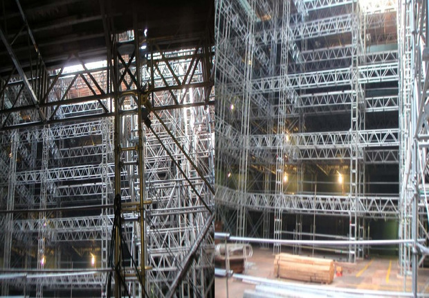
LNGC tank interbarrier space protection and scaffolding systems ensure the integrity of cryogenic tanks by preventing corrosion, reducing maintenance and enhancing safety. By combining tailored pressurization and inertization solutions, we create a stable, non-reactive environment that safeguards against moisture ingress and minimizes risks associated with tank degradation.
The custom-engineered scaffolding designs provide secure, efficient access for inspection, repair and maintenance operations within these confined spaces. Carefully integrated with protection systems, our scaffolding solutions prioritize ergonomics, adaptability and compliance with stringent regulatory standards, ultimately streamlining turnaround times and reducing operational expenditures for LNGC operators. By merging protection and access expertise, we deliver comprehensive, fit-for-purpose solutions that optimize LNGC tank performance and lifespan.
Interbarrier Spaces: Pressurization – Inertization
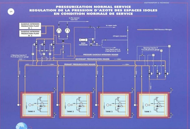
Interbarrier spaces must to be inerted with a suitable dry inert gas, usually nitrogen, and maintained at specified gas percentage and pressure. This nitrogen can come from a shipboard nitrogen generator or shipboard storage. Stored inert gas should be sufficient for normal consumption of at least 30 days.
Both inner barrier spaces (IBS) are purged with nitrogen via separate fill and monitor lines.
Nitrogen flows along different paths within Key Characteristics of Membrane Tanks Systemsthe tank containment systems. MARK III allows flow between hull and insulation panels, between panels and corrugations of membrane. NO.96 allows flow between hull and insulation boxes and under flat invar strips.
Flow is controlled by pressure-regulated valves at the entry and exit of the innerbarrier spaces. Regulating pressures are adjusted to compensate for changes due to loading/discharge and ambient whether/sea conditions.
The differential pressure between inner hull, secondary barrier and primary barrier is limited at 20 or 30 millibar according with the type of membrane system. The invar membranes are very sensitive to high differential pressure. A high pressure may inflate and destroy a membrane very quickly. To avoid possible damages, pressure indicators, alarms and controls are provided, as well as safety valve for the insulated spaces and the Independent Cargo Tankscargo tanks.
The purging flow controls the barrier atmosphere. The purge flow is continuously monitored for presence of methane (CH4) indicating a leak; at the same time the purge flow keeps any CH4 that may leak into the barrier space from reaching a hazardous concentration. Figure 1 shows the diagram of the system.
Scaffolding
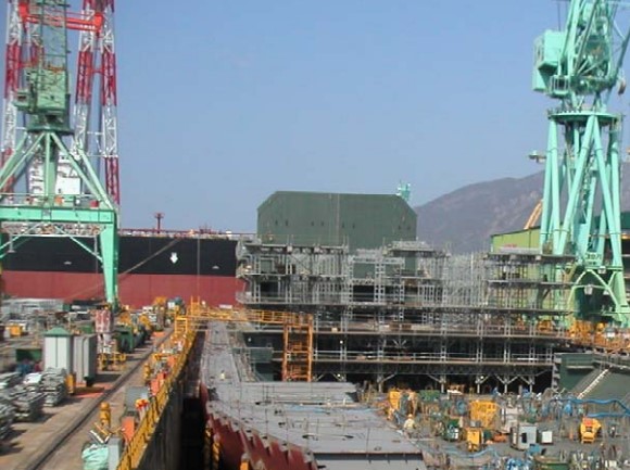
Prior starting Response of Insulation Materials to Heatthe insulation work, it is necessary to complete the erection of scaffolding in each cargo hold. Usually the scaffolding erection is made at the time of the dock erection. Figure 2 shows the installation of scaffolding in the building drydock.
The main features of the scaffolding are:
- Vertical retractable legs to allow to procede the insulation and membrane work on the bottom.
- Lower platform should be sufficient to provide enough space to work on the bottom.
- All platforms on their edges will be retractable of 0,8 m to allow the installation of the insulating panels and welding of the membrane.
- Standard distributed load on each leg should be below 2 bar.
At any time during installation, the pressure exerted by an individuale pad should not exceed 3,5 bar provided the distance between two adjacent leg axes is more than 600 mm. Sequence to lift the leg has to be defined by the yard.
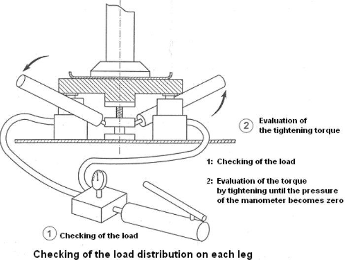
Load distribution check should be performed at the beginning of panel installation on the bottom. That will also allow indicate tightening amount to be applied each time that a scaffolding leg is removed/retracted.
Figures 3 and 4 show the arrangement of the platforms and of their retractable parts.
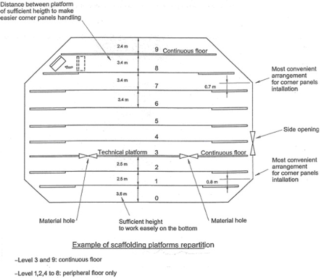
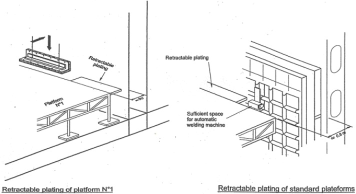
Figure 5 is a photograph showing leg supports during the installation.
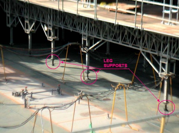
Figure 6 is the drawing of the leg support details.
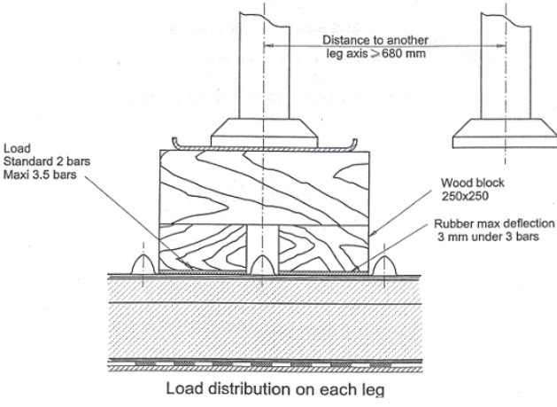
Figure 7 is the drawing of the tool for checking the weight distribution on each leg.
Next Figure 8 gives a general view of the scaffolding installed in a LNGC tank.
