For LNG tanks Insulation is important to maintain the low temperature required to keep the gas in its liquid form. Materials such as perlite, foam glass, or polyurethane foam are commonly used for LNG tank insulation. Proper insulation helps in preventing heat transfer and maintaining the integrity of the stored LNG.
Thermal testing of insulating materials is done to measure their ability to resist heat transfer. Common tests include thermal conductivity, heat capacity, and thermal resistance testing. These tests help determine the effectiveness of an insulating material in preventing heat flow, which is crucial for applications such as building insulation or thermal protection in various industries.
Thermal Loads on Insulation
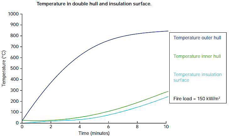
If there is an external fire adjacent to an LNG carrier the temperature of the tank cover and the hull structure will rise and eventually expose the insulation surface to thermal radiations and extended temperature.
The inner hull temperature of a membrane carrier in a fire exposure is shown in Figure 1.
The expected temperature development of the insulation surface below the weather cover for a Moss carrier is shown in Figure 2.
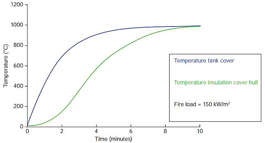
The analysis was based on a one dimensional transient heat transfer model with a fire load of 150 kW/m2 and a flame temperature of 1 000 °C.
These simple analyses show that the double hull structure for the membrane carriers and the bottom part of the Moss system offer efficient thermal protection of the insulation surface for 10-20 minutes, while Simplified Reapplication of the Code for Loss of Insulationinsulation surfaces of the upper part of the Moss spheres will reach a temperature above 100 °C after approximately 1-2 minutes.
Thermal Effects on the Insulation
The cargo tank insulation on the majority of LNG carriers is based on expanded plastic foams or plywood boxes filled with perlite. The plastic foams are sensitive to heat while the perlite filled plywood boxes are considered more robust (the main concern would be the integrity of the fixings, not the deterioration of the insulation).
Two basic types of foams are being used:
- Thermopolymers (polystyrene, expanded PVC etc);
- thermosetting polymers (polyurethane foams).
Their responses to high temperatures are fundamentally different:
- The thermo-polymers will start melting at a temperature between 100 and 150 °C. Initially a high viscosity liquid will form and the viscosity will reduce as the temperature increases. At significantly higher temperatures a chemical decomposition will start turning the liquid to solid decomposition products;
- the thermosetting foams will not melt. At temperatures between 250-500 °C a chemical decomposition will occur. The foam will change to a solid charred layer.
In the tank insulation the foam material is an integral part of the Training LNGC Course for ABS and Service Project Managers & Project Management OG LNGC Project in Koreainsulation panels. Normally the surface facing the fire load will have an aluminium protection. The panel will be indirectly exposed to the fire load by radiation from the inner hull or the inner side of the weather cover. The effective radiation load on the insulation will be dependent on the temperature of the inner hull/weather cover and the emissivity of the insulation protection.
A progressing damage to the insulation requires that the fire load is transferred deeper and exposes the underlying parts of the foam. This requires that the decomposed parts of foams (melted foam or char) disappear completely and do not restrict the transfer of heat to the undamaged parts of the foam.
If the damaged parts of the foam do not disappear the remains (char or a melted layer) will effectively delay the degradation.
It is anticipated that the metallic foil protection on top of the insulation provides effective protection by:
1 Reflecting a large part of the heat load due to low emissivity.
2 Preventing melted foam or char to escape.
If the decomposed insulation products are not removed, the complete degradation of the insulation will not occur, or will require prolonged fire exposure (> hours).
Partly damaged insulation will provide an effective reduction of the heat transfer to the cargo and limit the amount of boil-off. The steady state heat transfer through a degrading insulation has been estimated as shown in Figure 3.
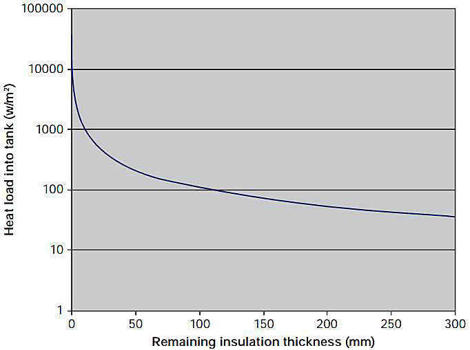
Figure 3 shows that any insulation or insulation products will protect the tank.
The key issue will therefore be if the fire load transmitted to the insulation is capable of being totally damaged and remove the insulation and the insulation cover.
We are not aware of a precise analytical model to predict the degradation of insulation material.
The above description of the failure mechanisms is based on results from experimental investigations carried out by DNV in the period 1975-1980.
Outline of DNV Test Programme
DNV conducted a series of tests of insulation material with the objective to determine the thermal damage to plastic foams exposed to high temperatures and radiant heat. The investigation was carried out in two parts.
Part one tested the extent of weight loss on decomposition; this was done by putting test pieces of insulation foams into an oven and the extent of weight loss measured. The procedure was followed for different times and temperatures in both air and inert atmospheres.
Part two tested the behaviour of the insulation foam as part of an insulation panel when exposed to radiation on one side only. In this way one could predict the behaviour of the insulation when a temperature gradient is present. These tests were conducted in conjunction with «Firetechnical Laboratory», Technical University of Norway, Trondheim.
The first part of the tests demonstrated that the thermo-polymer started to shrink and gradually melted when the temperature was increased 100-150 °C. The melted product was a high viscosity fluid and the viscosity reduced when the temperature increased.
The thermosetting foams did not melt. At temperatures above 200-300ºC a chemical process started and the foam converted into a solid (but brittle) char.
It was realised that the remaining melted foam or charred parts of the thermosetting form could offer protection to the underlying foam and the objective of the second set of tests was to investigate these protective effects in inhibiting the degradation of insulation panels exposed to radiant heat loads.
Read also: Materials of construction LNG and LPG tanks
The second test programme was performed exposing insulation panels with and without a metallic cover to radiant heat load for prolonged periods of time.
A propane gas heated steel plate (500 × 400 mm) served as radiation source (emissivity 0,8). The temperature of the plate was controlled by regulating the propane and air supply. The tests were carried out with a radiator temperature of up to 800ºC, corresponding to a heat load of 75 kW/m2.
Each test panel (1 400 × 1 300 mm) was made up of 100 mm thick insulating material either glued (extruded polystyrene) or foamed in Situ (polyurethane) to a 1 min thick steel plate. 11 panels were tested, 8 polyurethane and 3 extruded polystyrene. 3 polyurethane panels were tested without shield, 3 with Aluminium shield and 2 with galvanised steel shield. All the extruded polystyrene panels had aluminium shield.
The tests were carried out until a significant temperature increase was observed on the cold side.
The test of unprotected polyurethane with 75 kW/m2 lasted for 1 hour. All tests of panels with metallic surface protection had a typical duration of 3-4 hours before the temperature rise on the cold side was observed.
In all cases the foam thermally decomposed to varying degrees, but ignition did not occur.
It should be pointed out that the Aluminium foil and Galvanised steel plates were very effective in reflecting a large portion of the incident radiant heat. This indicates that the Al. foil/Galv. steel act as good thermal radiation barriers.
When polyurethane foam thermally decomposes char formation is initiated, covering the entire exposed area. This char did not burn and acted as an insulator.
Extruded polystyrene behaved in a different way as this material melted and transformed into a rubbery or viscous substance. This substance covered the entire exposed surface, thereby protecting the underlying material.
Results
1 Critical temperatures for the polyurethane and polystyrene (expanded and extruded) were around 200 °C and 100 °C respectively. Below these temperatures no significant deterioration of mechanical or thermal properties occurred.
2 The results are conservative as the effects of cooling from the cargo (and the initial low temperature in the foam) was not included.
3 These tests were conducted in a small scale. The effects of scaling are not known and there might be some questions about what might happen to the reflecting barrier when considered on a bigger scale.
4 One test was conducted where the entire surface was exposed to radiant heat to see if the insulation would fall off under action of its own gravity. The result was positive, ie the insulation did not fall off.
5 Aluminium foil and galvanized steel plates acted as very effective reflecting barrier.
6 Test result part one shows that inert atmospheres do not have any significant effect on weight loss on decomposition. It is, however, likely that inert atmosphere may have positive effects on fire propagation in non self-extinguishing insulation; but the same effect (without inert gas) is obtained when he insulation is self-extinguishing. It is important to note that ignition never occurred in part two of the tests.
During the progression of the working group studies it became clear that, for this complex issue of how a large fire scenario may a) emit heat to a high sided vessel and b) affect the internal materials and structure of an LNG carrier, there were many areas of uncertainty. The studies presented capture both steady state and time based calculations, the basis of which rely on knowledge of, or assumptions for, fire scenario conditions.
Given the uncertainty existing within the industry over large pool fire Surface Emissive Powers and how these are likely to impact a carrier structure, it was not possible to gain unanimous agreement in all respects. However, the vast majority came to agree with the conclusions and recommendations made in chapters 10 and 11.
Steady State Conditions
Full agreement was achieved on the steady state conditions, which indicate that in the extreme case of losing the entire insulation layer, then assuming that the factors included in the IGC Code for sizing the relief valves, the valves are capable of relieving the anticipated vapour albeit at raised tank pressures that can be withstood by the cargo tanks. Additionally, this relief valve capability can, as well as loss of insulation, also comfortably accommodate the further extreme case of complete loss of the weather cover of a Moss type LNG carrier.
The above observations include reliance on two elements included in the IGC Code method for deriving pressure relief valve sizing:
- That the Fire Factors assumed in the IGC Code are valid, particularly for environmental factors. The full working group agreed that they were valid. An exhaustive search by the working group members revealed no calculated basis for the Fire Factors, but were based on industry experience and determined by the developers of original GC Code, the predecessor of the IGC Code, in the 1970s.
- Surface Emissive Power assumed by the IGC Code are valid. Study by the working group revealed that this value (see chapter 2) is used by many similar codes in the wider industry such as CGA and API. However, this value has been challenged for larger LNG fires and large pool fire tests have been commissioned by the USA Department of Energy (DoE). The working group recognised this uncertainty and, despite an extensive examination of previous industry studies, could not conclude that an alternative, definitive value should instead be used and therefore led to the inclusion of Recommendation 1. It was also recognised by the group that considering the inclusion of this value for heat input in many codes and standards in the hydrocarbon process industry, pool fire tests could potentially impact all of these codes.
For steady state conditions, no credit or account has been made for either the pressure relieving capability of the vapour header or the ability to apply the water deluge and fire fighting system onboard an LNG carrier, ensuring that the conclusions of the studies and this report are conservative.
Time Based Conditions
Heat transfer and CFD calculations were performed, a review of previous studies on insulation tests was undertaken and further insulation heat tests were performed. These are set forth in chapters 6, 7 and 8 and in Appendices 2, 3, 5, 6 and 7. A range of times for complete degradation of insulation were indicated through the various studies and tests such that definitive time could not be arrived at due to the conflicting evidence and differing views of the working group members. For this reason, Recommendation 2 is made.
Decisions and Agreement of the Working Group
Despite the studies carried out above and given the recommendations made, unanimous agreement could not be arrived at by the entire working group. However, complete agreement was reached for conclusions 1, 2, 3, 4, 5 and 6. The vast majority agreed with conclusions 7, 8 and 9, leaving only professor Havens not in agreement.
Recommendations 1 and 2 were agreed.
In addition, and although not raised at any working group meeting, the compliance of cargo tank polystyrene insulation materials was challenged due to a lack of fire resistance, although no specific paragraph of the IGC Code could or would be referenced in this respect. It was the opinion of the group that this stood outside of the working group Terms of Reference and that it is the remit of a regulatory body to assess this and that it has done so bearing in mind the historical continued certification of such materials over the past 35+ years. Given that the IGC Code is under review at the time of writing, this can be addressed at this time.
Conclusions
1 IGC formula and methodology for LNG carrier relief valve sizing compares favourably and is consistent with similar codes such as API, CGA, EN, ISO and NFPA.
2 For the Moss design tank with polystyrene based foam insulation, assuming the worst case scenario of losing the entire insulation effect, the tank pressure will rise to a level that can be accommodated by the tank structure without failure. This is due to the capability of the LNG carrier relief valves to relieve far higher gas flow capacities with rising tank pressure, as indicated by calculations based on the methodology prescribed by the IGC code.
3 Further to 2; due to the capability of the relief valves to accommodate greater gas flows with rising tank pressures and assuming the worst case of cargo tank cover damage and loss of heat shielding due to the possibility of combustion of the insulation and degradation of products causing over-pressures sufficient to fail the tank cover, the relief valve capacity is still sufficient to prevent over-pressure failure of the tank.
4 In addition to conclusions 2 and 3, where even if the entire insulation was lost and the tank cover was completely lost, the capacity of the relief valves can accommodate a further estimated 30 % rise in heat flux from a surrounding fire above that contained in the codes referred to in 1.
5 The limit of relief valve capability is the «choke point» at which no further increase of gas flow can be accommodated through the RV vent system. This is approximately at 4,3 barg.
6 The presence and use of the vapour header will provide further pressure relief via the assumed damaged (holed) cargo tank and the forward vent riser. However, this has not been relied upon for the protection of the cargo tank against over pressure in the points above. The extent to which the vapour header contributes to pressure relief will depend on the fire scenario.
7 The response of the insulation system to heat, with time, is unclear; a detailed understanding of rates of insulation degradation and recession was not available for the structural arrangement of an LNG carrier. One dimensional CFD/heat transfer calculations made by the working group indicated time periods of 10 minutes for a complete degradation to a depth of 30 cm. Conversely, other studies in this report result in a degradation time of up to 29 minutes. Additionally, reports from physical tests carried out in the 1970s indicate time periods of greater than 2 hours, although in these tests, the conditions did not entirely accurately reflect actual LNG carrier dimensions or heat source temperatures.
8 From the behaviour tests of polyurethane foam under heat in an N2 inerted atmosphere, insulation properties and strength are retained such that the concern for complete failure by degradation under fire conditions is likely to be substantially less for polyurethane based materials.
9 Based on experience from earlier fire incidents and studies included in the report, the tank cover is not likely to collapse under fire loads. It should be noted that the ABS study did not take into account the effect of the water-spray system required under 11.3 of the IGC Code.
Recommendations
1 If large scale LNG fire tests are carried out by Sandia, or others, that show significant conflict with existing values of heat flux used in the IGC Code and other industry codes and standards, the question of the current equations for determining fire-case pressure relief loads merit re-examination by the whole LNG industry and not just the shipping element.
2 Although the working group has determined that current polystyrene foam insulated Moss sphere LNG carriers are equipped with pressure relief valves that provide additional capacity to prevent failure by over-pressure of intact cargo tanks, a better understanding of the foam plastic insulation vulnerability to heating is required to adequately assess the hazards that could result from loss of insulation effectiveness with fire exposure. Given the comparatively short duration of LNG fires as estimated by previous fire scenario studies, a much better understanding of the temporal response of foam plastic insulation materials is necessary to determine the worst case circumstances as referred to in the conclusions above. Further research, which should include physical insulation testing as well as a determination of the potential for additional damage due to combustion of the foam degradation products, is recommended.