This guide provide technical information for the vessels, that will do conversion to use LNG as fuel.
- Introduction
- General context of ship conversions to liquefied natural gas (LNG)
- LNG and gas properties
- Main safety aspects
- Application
- Scope
- Classification
- Definitions and abbreviations
- Definitions
- Arrangement of an LNG-fuelled installation on board a ship
- Main components
- Typical arrangement of the gas-fuelled ship installation
- Guidelines for ship conversion
- Developing the LNG conversion solution
- Safety analysis
- Extent of the modifications.
- Guidance for the design and installation of the gas-related systems
- LNG storage installation
- LNG bunkering station
- Fuel gas handling system
- LNG and gas fuel piping
- Gas valve units (GVUs)
- Gas combustion unit (GCU)
- Vent mast
- Inert gas system
- Gas detection system
- Fire extinguishing system
- Heating systems for LNG vaporization and gas heating
- Emergency shutdown (ESD) systems
- Guidance for the modification of existing installations
- Creation of airlocks
- Modification of the ventilation installation
- Gas safe machinery spaces vs. ESD protected machinery spaces
- Vent lines
- Gas conversion of engines
- Exhaust systems of engines
- Consequences of the gas conversion on the EEDI index of the ship
- Major conversion
- Impact of the gas conversion of the ship
Introduction
General context of ship conversions to liquefied natural gas (LNG)
The conversion of a ship to LNG may be decided for different reasons, such as:
- environmental reasons (reduction of NOx and CO2 emissions, elimination of SOx emissions) in particular in case of regulatory developments;
- economic reasons (natural gas prices);
- availability reasons (expansion of LNG bunkering network).
The LNG conversion may be such that the ship keeps its original range with fuel oil or it can allow the ship to operate with LNG only in certain conditions, e.g. in ECA areas, at berth, etc.
The LNG conversion may affect the cargo or Questions and answers to Crew Evaluation System Test about Crowd Control Managementpassenger capacity of the ship.
LNG and gas properties
LNG Composition
LNG is a cryogenic liquefied mixture of hydrocarbons com-posed predominantly of methane and which can contain minor quantities of ethane, propane, butanes, pentanes,nitrogen or other components normally found in natural gas extracted from gas fields.
LNG density
The density of LNG depends on the composition and usually ranges from 420 kg/m3 to 470 kg/m3 at atmospheric pressure.
LNG boiling temperature
LNG has a boiling temperature depending on the composition, typically around −161 °C at atmospheric pressure.
Composition of LNG boil-off gas
The composition of the boil-off gas depends on the composition of the liquid. It changes in the course of time, because of the differences in the boiling points of each LNG component, ranging from −196 ºC to +69 ºC. The main components of boil-off gas are methane and nitrogen. The list of components with their boiling point is given in Table 1.
- Note 1: The nitrogen molar content in the gaseous phase can be much higher than in the liquid phase. For an LNG with 1 % Nitro-gen in the liquid phase, this content can reach 25 % in the gaseous phase at atmospheric pressure.
- Note 2: One volume of LNG produces approximately 575 volumes of gas at normal conditions and 600 volumes at standard conditions (respectively 0 °C and 15 °C at atmospheric pressure).
| Table 1. Boiling points of LNG components | |
|---|---|
| Component | Boiling point (atmospheric pressure) |
| Nitrogen | -196 °C |
| Methane | -161 °C |
| Ethane | -89 °C |
| Propane | -42 °C |
| i-Butane | -12 °C |
| n-Butane | -1 °C |
| i-Pentane | +28 °C |
| n-Pentane | +36 °C |
| n-Hexane | +69 °C |
Density of LNG boil-off gas
Density of LNG boil-off gas at atmospheric pressure is approximately:
- 0,67 kg/m3 at 20 °C (pure methane);
- 0,72 kg/m3 at 0 °C (pure methane);
- 1,2 kg/m3 at −113 °C (pure methane);
- 1,8 kg/m3 at −161 °C (pure methane);
- 1,2 kg/m3 at −87 °C (80 % methane, 20 % nitrogen).
The above figures are to be compared to the density of air: 1,2 kg/m3 at 20 °C and atmospheric pressure. It explains the different phases of gas dispersion in case of release:
- cold boil-off gases below −113 °C (pure methane) or −87 °C (80 % methane, 20 % nitrogen) are denser than air and tend to descend in air or to spread over ground or obstacles;
- heated by the environment, hot boil-off gases with temperature higher than mentioned above are lighter than air and tend to rise in atmosphere or to spread below decks.
Flammability
The flammability characteristics of pure methane are as follows:
- flammable range of methane/air mixture is 5 % (low flammability level: LFL) to 15 % (high flammability level: HFL) by volume at ambient conditions;
- auto-ignition temperature: 537 °C (higher than that of marine gas oil (MGO): 300 °C);
- minimum ignition energy: 0,25 mJ, lower than that of many hydrocarbons.
Compared to pre-heated MGO, inflammation of natural gas on hot surface is less likely to happen than spark ignition. LFL, auto-ignition temperature and minimum ignition energy of natural gas (containing hydrocarbons heavier than methane) are lower than the above figures.
Visibility
LNG vapors are not visible. However, LNG leaks in humid atmosphere generate visible mist due to the condensation of air moisture.
Main safety aspects
The main safety aspects associated with the use of methane as fuel include:
1 risks of fire and explosion after vaporization of LNG into a gaseous state;
2 risks in connection with cryogenic temperatures in case of LNG leakage, spillage or spraying:
- embrittlement and cracking of parts of the ship structure and components made of ordinary steel.
- frostbite on contact with LNG or cold surfaces.
3 risk of asphyxiation induced by high concentrations of methane since it displaces the oxygen in the air.
Application
Scope
This guidance note is intended to provide technical information to owners, designers and shipyards about the design features to be considered for ships that undergo a conversion in order to use natural gas as fuel.
Except as otherwise stated in this document, it applies to all types of ships.
This guidance note does not take into consideration the economic aspect of the ship conversion.
Classification
Where the ship is classed with Bureau Veritas, the LNG conversion is to be carried out in accordance with Rule Note NR529, Gas-fuelled ships (here in after referred to as NR529). The relevant documents, as listed in NR529, Table C2.1, are to be submitted to the Society for review.
When the LNG conversion of a BV-classed ship is carried out to the satisfaction of the Society, the additional service feature gas fuel (LNG) or dual fuel (LNG) will be assigned to the ship.
The attention is drawn to the possible consequences of the LNG conversion of a ship on:
- the NOx certification of the engines, when they are converted to DF engines (see MARPOL Annex VI, Reg.13.2.1.2).
- the EEDI of the ship, in particular when the LNG conversion of the ship is considered as a major conversion(see MARPOL Annex VI, Reg. 2.24.5).
Definitions and abbreviations
Definitions
LNG conversion
LNG conversion means all the modifications brought to the ship to allow the onboard use of Liquefied Natural Gas (LNG) as fuel. It covers in particular the following systems:
- bunkering system;
- storage tanks;
- fuel gas handling system;
- fuel gas supply system;
- fuel gas consumers;
- pressure relief systems;
- fuel gas detection systems;
- emergency shutdown systems;
- fire protection.
Fuel gas handling system
Fuel gas handling system means the equipment necessary for processing, heating, vaporizing or compressing the LNG or gas fuel.
Gas valve unit (GVU)
Gas valve unit means a set of shut-off valves, venting valves, pressure control valve, gas flow meter filter and gas pressure/ temperature transmitters and gauges, located on the gas supply to each gas consumer.
Gas combustion unit (GCU)
Gas combustion unit means a system primarily intended for the combustion of boil-off gas in excess.
Dual-fuel (DF)
Dual-fuel applies to engines and boilers designed for operation with oil fuel only and gas fuel only (or in some cases with oil fuel and gas fuel in variable proportions) and capable of switching over to operation with the other type offuel.
Gas-related space
Gas-related space means a space containing:
- installations or equipment intended for the storage, handling and supply of LNG and gas fuel;
- gas consumers (engines, boilers or GCU).
Gas safe machinery space
Gas safe machinery space means a machinery space so arranged that the space is considered gas safe under all conditions, normal as well as abnormal conditions, i.e. inherently gas safe.
ESD-protected machinery space
ESD-protected machinery space means a machinery spaces so arranged that the space is considered non-hazardous under normal conditions, but under certain abnormal conditions (gas leakage) may have the potential to become hazardous. In the event of abnormal conditions involving gas hazards, emergency shutdown (ESD) of non-safe equipment(ignition sources) and machinery is performed automatically.
Low pressure
Low pressure means a maximum working pressure equal to or less than 10 bar.
High pressure
High pressure means a maximum working pressure greater than 10 bar.
Very high pressure
Very high pressure means a maximum working pressure greater than 20 bar.
Double wall arrangement
Double wall arrangement of a liquid or gas fuel pipe means that the liquid or gas fuel pipe is enclosed in a pipe or duct maintained in negative pressure by an extraction ventilation system or pressurized with inert gas in accordance with the provisions of NR529, [9.5] and [9.6].
Master gas fuel valve (MGFV)
Master gas fuel valve is an automatically operated valve located on the gas supply line to each gas consumer or set of consumers and that automatically cuts off the gas supply when activated by the safety system.
Methane number (MN)
Methane number is a fuel quality indicator reflecting the resistance of a fuel gas to engine knocking.
Energy efficiency design index (EEDI)
The Energy Efficiency Design Index (EEDI) is an index developed by IMO that is used to calculate the energy efficiency of a vessel. The EEDI of a ship (attained EEDI) is calculated using a formula that takes the ship’s emissions, capacity, and speed into account. This value must not exceed a given threshold (required EEDI).
Tank connection space (TCS)
Tank connection space is a space surrounding all tank connections and tank valves that is required for tanks with such connections in enclosed spaces.
Arrangement of an LNG-fuelled installation on board a ship
Main components
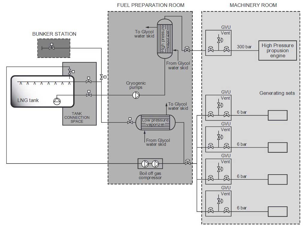
The gas fuel installation of a typical LNG-fuelled ship consists of the following main components:
- bunkering stations;
- insulated LNG storage tank with a tank connection space containing tank valves and instruments;
- gas handling system (vaporisers, heaters, compressors),located in the fuel preparation room (some components may also be located in the TCS);
- LNG and gas fuel piping system;
- venting systems and vent mast;
- gas valve units;
- gas consumers (diesel engines, gas turbines, boilers);
- auxiliary systems (heating system for LNG vaporisation and gas heating, inert gas system, LNG tank pressure /temperature control systems including gas combustion unit);
- monitoring, control and safety systems (including gas detection and emergency shutdown systems);
- communication system between the ship and the bunkering facility.
Typical arrangement of the gas-fuelled ship installation
A typical arrangement of a gas-fuelled ship installation showing the main components is given on Picture 1.
Guidelines for ship conversion
Developing the LNG conversion solution
Main options
The main options to be considered for the LNG conversion of the ship include:
- the type, capacity and location of the LNG storage tanks LNG tanks are to be fitted with pressure relief valves connected to a vent mast. See NR529x;
- LNG transfer from the tank to the vaporizers by pump or by pressurization of the tank (for type C tanks);
- the arrangement of the machinery spaces (“gas safe” or “ESD-protected” spaces);
- the operating principle of the engines in gas mode (lean burn Otto or Diesel cycle) and the required gas supply pressure (of the order of 5 to 15 bar for lean burn Otto cycle and 300 to 350 bar for Diesel cycle);
- the bunkering source (characteristics of the LNG);
- method for boil-off management.
Safety analysis
An HAZID study is to be carried out, covering at least the following spaces, zones and systems:
- tank connection space (TCS);
- enclosed and semi-enclosed fuel preparation rooms;
- enclosed and semi-enclosed bunkering stations;
- spaces containing very high pressure gas or liquid fuel piping;
- ESD-protected machinery spaces;
- GVU spaces;
- zones where vent lines and safety valve discharge lines are led, except where ventilation inlets to accommodation and machinery spaces are provided with gas detection arrangements;
- containment systems and adjacent structure.
Gas dispersion analyses may be required for:
- ESD-protected machinery spaces;
- enclosed and semi-enclosed bunkering stations.
Extent of the modifications.
The following systems or equipment are to be added and appropriate spaces or areas are to be available to accommodate them:
- LNG storage tanks and associated supports and modifications of the ship structure (reinforcements);
- LNG bunkering station;
- fuel gas handling system;
- gas supply lines to the consumers including MGFV and GVU;
- GCU, where required In pursuance of NR529, [6.9.1.1], the pressure in the tank is to be maintained below the set pressure of thetank pressure relief valves for at least 15 days, assuming full tank at normal service pressure and the ship in idle condition, i.e. only power for domestic load is generated. For type C tanks, this may be fulfilled by pressure accumu-lation in the tank. In such case, attention is to be paid to the thermal expansion of the liquid due to the pressure / temperature increase and to the consequent limitation of the filling ratio of the tank. Where necessary for other types of tanks, the following methods should be considered: reliquefaction of vapours; thermal oxidation of vapours in a boiler or dedicated oxidizer (gas combustion unit); liquefied gas fuel cooling.x;
- vent mast;
- nitrogen system;
- fire containment;
- gas detection systems;
- fire detection and fire extinguishing systems;
- heating systems for LNG vaporization and gas heating;
- control, monitoring, alarm and safety systems for gas-related systems.
The following systems or equipment are to be replaced or modified to suit gas operation:
- diesel engines;
- boilers;
- ventilation systems;
- safety arrangements for exhaust systems, lubricating oil systems, crankcase, etc;
- electrical equipment used in gas dangerous areas orspaces.
The presence of the new installations and equipment may result in new hazardous area zones (see NR529, [12.5])and specific requirements may have to be fulfilled for:
- access;
- ventilation;
- segregation between hazardous spaces and gas safe spaces (provision of air locks);
- electrical equipment (certified safe type).
For spaces designed to contain possible LNG leak-age, it should be ensured that the resistance of the space boundaries to cryogenic leakage and to pressure build up due to LNG vaporization is sufficient.
The stability and the longitudinal strength of the LNG-converted ship are to be assessed.
Guidance for the design and installation of the gas-related systems
LNG storage installation
The determination of the required LNG storage capacity is a key factor for an LNG conversion project. This capacity is to be based on the operating profile of the ship including the expected bunkering periodicity.
The types of the LNG storage tanks may be: mem-brane tanks, type B prismatic tanks or type C cylindrical or multilobe tanks, or any other type of tank approved in accordance with the relevant provisions of the NR529. The following technical aspects are to be taken into account to select the most suitable arrangements:
- location of the tank (on open deck or in enclosed spaces below deck) and orientation (vertical or horizontal);
- design limitation (size) of the type of tank considered;
- volume required for hold space (loss of cargo or passenger carrying capacity);
- weight of the tank and of the necessary supporting structure (reduced deadweight capacity);
- impact of the tank installation on the ship stability The stability and the longitudinal strength of the LNG-converted ship are to be assessedx;
- design pressure and capability of the tank to with stand pressure build-up In pursuance of NR529, [6.9.1.1], the pressure in the tank is to be maintained below the set pressure of thetank pressure relief valves for at least 15 days, assuming full tank at normal service pressure and the ship in idle condition, i.e. only power for domestic load is generated. For type C tanks, this may be fulfilled by pressure accumu-lation in the tank. In such case, attention is to be paid to the thermal expansion of the liquid due to the pressure / temperature increase and to the consequent limitation of the filling ratio of the tank. Where necessary for other types of tanks, the following methods should be considered: reliquefaction of vapours; thermal oxidation of vapours in a boiler or dedicated oxidizer (gas combustion unit); liquefied gas fuel cooling.x;
- LNG transfer by pump (submerged or not) or by pressurization of the tank.
Portable tanks may be used in accordance with the provisions of NR529, [6.5], subject to a risk analysis addressing the specific risks arising from the use of such tanks.
In order to protect the tanks from external damage caused by collision or grounding, the distances between the tank boundary and the shell plating are not to be less than the minimum distances required in NR529, [5.3.3]. The alternative probabilistic approach (see NR529, [5.3.4]) maybe considered, resulting in smaller distances.
The installation of the tank below deck involves specific arrangements in terms of ventilation, gas detection, segregation from adjacent spaces, access and hazardous area classification, in addition to cut-outs in the shell plating to install the tanks.
Where located below the deck, the tank connections are to be located in a dedicated gastight space (TCS), capable of containing a possible leakage.
Where located on open deck, the deck is to be protected from potential leakage by a drip tray.
Where the tank is located on open deck, a water spray system is to be installed for cooling and fire prevention of the exposed parts of the tank, the tank connections and the fuel preparation equipment.
Where located on open deck, tanks are to be located at least 10 m from the superstructure and deckhouse boundaries, except when the water spray system provides sufficient coverage thereof. The superstructure facing the tank is to be insulated to “A-60” standard.
In pursuance of NR529, [6.9.1.1], the pressure in the tank is to be maintained below the set pressure of the tank pressure relief valves for at least 15 days, assuming full tank at normal service pressure and the ship in idle condition, i.e. only power for domestic load is generated. For type C tanks, this may be fulfilled by pressure accumulation in the tank. In such case, attention is to be paid to the thermal expansion of the liquid due to the pressure / temperature increase and to the consequent limitation of the filling ratio of the tank. Where necessary for other types of tanks, the following methods should be considered:
- reliquefaction of vapours;
- thermal oxidation of vapours in a boiler or dedicated oxidizer (gas combustion unit);
- liquefied gas fuel cooling.
LNG tanks are to be designed and built in accordance with the relevant provisions of NR529, [6.4].
LNG tanks are to be fitted with pressure relief valves connected to a vent mast. See NR529, [6.7].
LNG tanks are subject to maximum filling and loading limits in accordance with NR529, [6.8].
The local structural reinforcements in way of the tanks are to be calculated and effectively carried out onboard the ship.
LNG bunkering station
Enclosed or semi-enclosed bunkering stations located below the deck are to be arranged with an air lock to ensure the segregation of the bunkering station towards the adjacent spaces of the ship.
The bunkering station is to be located as close as possible to the tank in order to minimize the length of the bunkering piping and limit LNG heating during the transfer.
The location of the bunkering station, on or below deck, is to take into account the hazardous areas around bunkering connections (4,5 m radius) and the consequences of a possible leakage.
The bunkering connection is to be designed and arranged considering the following:
- size, number and position of the manifolds;
- expected bunkering rate;
- type of the connector;
- need for vapour return line;
- ESD connection;
- compatibility with the bunkering facility;
- interference between the bunkering operations and ship loading / unloading operations;
- extent of the hazardous areas, as defined in NR529, [12.5] and IEC standards 60092-502 and 60079-10-1;
- extent of the safety zone, as defined in ISO standard 20519:2017.
The following arrangements are to be made to protect the ship structure (deck and shell plating) in case of LNG leakage:
- drip tray below bunkering connections;
- a water curtain in way of the hull under the bunkering manifold.
Fuel gas handling system
Fuel gas handling systems containing high pressure components are normally to be located on an open deck.
Low pressure (below 10 bar) fuel gas handling systems may be located:
- in a dedicated room below deck (fuel preparation room);
- in the TCS (with the exception of pumps).
The fuel preparation room or area is to be arranged to safely contain cryogenic leakages and pressure build up in the room.
The fuel preparation room or area is to be considered as a hazardous area zone 1.
Where located below deck, the fuel preparation room is normally to have an independent access direct from the open deck. Where a separate access from deck is not practicable, an airlock is to be provided.
LNG and gas fuel piping
LNG fuel piping is to be arranged with a protective enclosure against leakage (double wall arrangement) except:
- in the TCS;
- in fuel preparation rooms;
- in enclosed or semi-enclosed bunkering stations;
- on open decks.
Gas fuel and LNG vapour piping is to be arranged with a protective enclosure against leakage (double wall arrangement) except:
Drip trays are to be provided:
- in way of fuel storage tanks on open decks Where located on open deck, the deck is to be protected from potential leakage by a drip tray.x;
- at the bunkering station The following arrangements are to be made to protect the ship structure (deck and shell plating) in case of LNG leakage: drip tray below bunkering connections; a water curtain in way of the hull under the bunkering manifold.x;
- in fuel preparation rooms, in way of possible liquid fuel leakage sources (including detachable pipe connections, pumps, valves and heat exchangers).
The volume of the drip trays is to be determined on the basis of:
- the leakage scenario determined in the HAZID analysis An HAZID study is to be carried out, covering at least the following spaces, zones and systems: tank connection space (TCS); enclosed and semi-enclosed fuel preparation rooms; enclosed and semi-enclosed bunkering stations; spaces containing very high pressure gas or liquid fuel piping; ESD-protected machinery spaces; GVU spaces; zones where vent lines and safety valve discharge lines are led, except where ventilation inlets to accommodation and machinery spaces are provided with gas detection arrangements; containment systems and adjacent structure.x;
- the time necessary for detecting the leakage;
- the time necessary for closing the concerned isolation valve.
Gas valve units (GVUs)
The GVU is a pressure control and safety system allowing the engine to be safely operated in the gas mode. The GVU is equipped with block-and-bleed valves (automatic stop valves and venting valves) that shut off the gas supply and vent the gas supply piping at the end of the gas operation and when some failures occur. The GVU also allows the purging of the gas piping system with inert gas, in particular before maintenance.
The GVU may be located in:
- a dedicated room adjacent to the engine room;
- the fuel preparation room;
- a gastight enclosure located within the engine room;
- the TCS (except for high pressure fuel systems).
The GVU is to be located as close as possible to the engine so as to reduce its response time in case of load variation and limit the amount of gas released in case of leakage. Relevant requirements from gas consumer manufacturers are to be fulfilled (10 or 15 meters max. depending on engine manufacturers).
Gas combustion unit (GCU)
A GCU (or thermal oxidizer) may be required to dis-pose of the natural boil-off gas generated in the fuel storage tank, in order to prevent excessive pressure, build up in the tank In pursuance of NR529, [6.9.1.1], the pressure in the tank is to be maintained below the set pressure of thetank pressure relief valves for at least 15 days, assuming full tank at normal service pressure and the ship in idle condition, i.e. only power for domestic load is generated. For type C tanks, this may be fulfilled by pressure accumu-lation in the tank. In such case, attention is to be paid to the thermal expansion of the liquid due to the pressure / temperature increase and to the consequent limitation of the filling ratio of the tank. Where necessary for other types of tanks, the following methods should be considered: reliquefaction of vapours; thermal oxidation of vapours in a boiler or dedicated oxidizer (gas combustion unit); liquefied gas fuel cooling.x.
A GCU is a bulky equipment that may require significant space and structural reinforcements for its installation. The impact of the GCU installation on the ship stability is to be investigated.
For the determination of the GCU capacity, the gas consumption corresponding to the engine power necessary for the permanent domestic load can be taken into account.
The minimum gas pressure necessary for the GCU operation has to be considered for the selection of the GCU. It is pointed out that some types of GCU are capable of being operated in free flow conditions (without compressor).
Vent mast
The vent mast allows the safe discharge of gas vapour from:
- tank relief valves in case of emergency;
- vent lines;
- etc.
The vent mast discharge height is not to be less than:
- B/3 or 6 m, whichever is the greater, above the weather deck and;
- 6 m above working decks and walkways.
Vent mast height can be limited to lower values for operational reasons, subject to the Administration’s agreement. Foldable mast may be accepted where necessary for the ship to pass under a bridge, subject to the Administration’sagreement.
The vent mast discharge is normally to be located at least 10 m from:
- air intake, air outlet and opening to accommodation and other non-hazardous areas, and;
- exhaust outlets from machinery installations.
The location of vent mast has to take into account the hazardous areas around the discharge outlet (4,5 m radius).
Inert gas system
Arrangements are to be made for gas freeing of fuel tanks and bunkering lines by means of inert gas. The source of inert gas may be external to the ship.
For fuel containment systems other than type C independent tanks, a shipboard inert gas generation system or shipboard storage is to be provided for inerting the interbarrier and fuel storage hold spaces, with a capacity corresponding to at least 30 days consumption.
Gas detection system
Gas detectors are to be provided in all spaces where a gas leakage may occur, in particular in the following ones:
- machinery spaces and other enclosed spaces containing fuel piping or other fuel equipment without ducting;
- GVU spaces;
- TCS spaces and space where access to the TCS is located;
- enclosed and semi-enclosed bunkering stations;
- double wall space between gas pipe and secondary enclosure;
- compressor rooms and fuel preparation rooms;
- air locks;
- gas heating circuit expansion tanks.
Gas detection is to be continuous without delay.
Fire extinguishing system
A water spray system is to be installed for cooling and fire prevention to cover exposed parts of fuel storage tank(s) located on open deck. See this Where the tank is located on open deck, a waterspray system is to be installed for cooling and fire preven-tion of the exposed parts of the tank, the tank connectionsand the fuel preparation equipment.x and this Where located on open deck, tanks are to be locatedat least 10 m from the superstructure and deckhouseboundaries, except when the water spray system providessufficient coverage thereof. The superstructure facing thetank is to be insulated to “A-60” standard.x.
A permanently installed dry chemical powder fire-extinguishing system is to be installed in the bunkering station area.
One portable dry powder extinguisher of at least 5 kg capacity is to be installed near the bunkering station (in addition to any other portable fire extinguishers required elsewhere by IMO instruments).
Heating systems for LNG vaporization and gas heating
Heating systems are to be provided for LNG vaporization and gas heating.
For the location of vaporizers and heaters Low pressure (below 10 bar) fuel gas handling sys-tems may be located: in a dedicated room below deck (fuel preparation room); in the TCS (with the exception of pumps).x.
Where necessary in order to avoid freezing, heating systems are to be arranged with an intermediate low freezing circuit. This circuit typically uses water-glycol as heat transfer fluid, which is heated in a waste heat recovery unit (using e.g. engine cooling water circuit) and rejects heat to vaporize LNG. The water-glycol circuit includes an expansion tank with gas detection to detect a possible leak in the LNG vaporizer.
For gas-only plants using engine cooling water or lubricating oil as heating medium for LNG vaporization and gas heating, arrangements are to be made for starting from dead ship conditions.
Emergency shutdown (ESD) systems
An ESD (emergency shutdown) system is to be provided ensuring the following automatic actions:
- shutdown of the LNG and vapour transfer in case of an emergency during the bunkering operation;
- shutdown of the tank valves and / or gas supply to the consumers in case of LNG or gas leakage detection.
Guidance for the modification of existing installations
Creation of airlocks
Airlocks may be required where necessary to separate hazardous spaces from those non-hazardous spaces. See this Where located below deck, the fuel preparationroom is normally to have an independent access direct fromthe open deck. Where a separate access from deck is notpracticable, an airlock is to be providedx and this Access between an ESD protected machinery spaceand other enclosed spaces of the ship is to be arranged withan airlockx.
Modification of the ventilation installation
The ventilation ducting serving hazardous spaces is to be separate from those serving non-hazardous spaces.
Electric motors driving ventilation fans serving hazardous spaces are not be located in the ventilation duct sunless the motor is certified for the same hazard zone as the space served. The fans are to be of a an approved non-sparking construction.
The location of air inlets and outlets for hazardous and non-hazardous spaces is to fulfil the segregation requirements of NR529.
Gas safe machinery spaces vs. ESD protected machinery spaces
The machinery spaces containing low pressure gas consumers can be treated in two different ways:
1 as gas safe machinery space (inherently gas-safe space),which requires all the gas piping in that space to be protected by an enclosure against leakage (double wall arrangement);
2 as ESD-protected machinery space, which means that single wall arrangement may be accepted in that space. Such space is considered as gas safe, except in case of gas detection. In such a case, the non-certified safe electrical equipment is to be de-energized, the gas supply to the space is to be shut off. The following arrangements are to be made:
- electrical equipment which is necessary for the safety of the machinery space (such as emergency lighting, fire and gas detection, etc.) is to be of a certified safe type.
- the ventilation installation is to have a capacity not less than 30 air changes per hour-a gas detection is to be provided to detect any gas leakage in the space.
- the engines are to be distributed into 2 separate spaces.
Single walled piping in ESD protected machinery spaces should be limited to premixed engines and small engines where the double wall arrangement is not practicable.
All high pressure gas piping is to be double walled. Access between an ESD protected machinery space and other enclosed spaces of the ship is to be arranged with an airlock.
Vent lines
Vent lines from bleed valves, thermal safety valves and gas fuel pipe enclosures are to be led to the open air(vent mast or other suitable location).
Gas conversion of engines
It should be checked with the engine manufacturer if retrofit solutions are available for the concerned engines. Otherwise the engine is to be replaced by a new one, which may also require the replacement of the gearbox and of some auxiliary equipment.
The attention is drawn to the possible reduction of the maximum power rating (MCR) resulting from the con-version of a lean-burn engine, which may be critical if the engine is operated in the upper range. Increasing the engine bore may be necessary to maintain the available power at the required level.
Load response (ramp-up) time may be increased.
The influence of the methane number (MN) of the gas is to be taken into account as low MN (generally below 80)may result in the need for operating the engine at a lower load (de-rating).
The main components of the engines that need to be replaced may include:
- cylinder heads;
- cylinder liners;
- pistons;
- connecting rods;
- turbo-charger;
- fuel oil injection valve (in case of combined main / pilot fuel injection);
- control and safety systems.
The following components need to be added:
- gas admission valves;
- pilot fuel oil injection valve (if independent from main fuel injection valves);
- pilot fuel oil pump.
The EIAPP certification of the converted engine is to be carried out on a case by case basis.
The safety concept of the converted engine has to be issued by the engine manufacturer.
Exhaust systems of engines
The exhaust system of engines is to be equipped with explosion relief devices sufficiently dimensioned to prevent excessive pressure in case of explosion of unburnt gas in the system.
For single engine dual fuel propulsion plants, the explosion relief device is to be a self-closing spring-loaded valve that would allow operation of the engine on liquid fuel after an explosion in the exhaust duct of the engine.
A ventilation system is to be provided for flushing the complete exhaust system before starting the engine.
Consequences of the gas conversion on the EEDI index of the ship
Major conversion
The possible consequences on EEDI of the conversion of a ship to gas operation are to be analysed. Such a conversion should be considered as a major conversion with respect to MARPOL Annex VI, regulation 2.24.5,which reads as follows:
“Major Conversion” means in relation to chapter 4 of this Annex a conversion of a ship:[…] or 5 which substantially alters the energy efficiency of the ship and includes any modifications that could cause the ship to exceed the applicable required EEDI as set out in regulation 21.
Impact of the gas conversion of the ship
The following aspects at least should be considered to evaluate the impact of the gas-conversion of the ship on the attained EEDI:
1 Additional weight resulting from the LNG conversion (in particular LNG tanks and related structural modifications) and consequences on the ship capacity, as defined in Annex to Resolution MEPC.245(66), reg. 2.3
2 Specific energy consumption of the LNG-converted engine (gas and liquid fuel). It should be noted that the specific energy consumption of low pressure DF engines may be higher than that of the standard Diesel version of the engine.
3 Value of the CF factor Regarding the value of the CF factor to be used in the calculation of the attained EEDI of ships fitted with dual fuel engines, the attention is drawn to the criteria in Resolution MEPC.254(67) 2014 “Guidelines on Survey and Certification of the Energy Efficiency Design Index(EEDI)”, reg. 4.2.3. The CF factor for gas may be used subject to:
- final decision of the Administration;
- gas energy stored onboard ≥ 50 % of the total energy (gas + fuel) stored onboard.
Depending on the arrangements that will be adopted for the actual gas-conversion of the ship, compliance with the requirements of “Impact of the gas conversion of the ship” may result in an increase of attained EEDI and the gas-conversion of the ship should then be considered as a “major conversion”.
It is therefore advisable to evaluate the expected value of the attained EEDI of the ship on the basis of the extent of the intended modifications, before starting the gas-conversion work.