Natural gas has remained the fastest growing energy resource in most regions of the world for more than two decades. This article contains massive information about LNG fundamentals.
Introduction
For almost a century, natural gas has been transported safely, reliably, and economically via pipelines. Pipelines proved to be ideally suited to the supply and market conditions of the twentieth century, when large reservoirs of conventional natural gas are found in accessible locations. Pipelines provided the stability and security of supply and continue to do so where large accessible gas reserves remain. However, over the past decades it has become clear that significant quantities of new gas reserves are not so conveniently located. Attention has shifted to more isolated large gas reservoirs that were previously thought to be too remote, or technically too difficult and costly to develop.
A number of solutions for exploiting stranded gas reserves are currently being developed and considered for commercialization. On the other hand, over the past three decades, only the liquefied natural gas (LNG) industry has successfully brought many large remote gas fields to the gas markets that are unreachable by pipeline (e.g., Japan, South Korea). Today, the LNG supply chain shave diversified and introduced competition into markets previously “captured” by pipeline gas suppliers, and have improved the security of energy supply of many consuming nations and reduced the geopolitical and political constraints on global gas supply.
This chapter briefly summarizes the components of the LNG supply chain – the steps and industrial processes used in producing, storing, and delivering LNG to commercial and residential customers. For those readers new to the LNG industry and unfamiliar about what it is, how it is used, and its basic safety and environmental track record, Appendix 1 is included.
Monetizing stranded gas
Despite being one of the most abundant energy sources on the planet, more than one-third of global conventional natural gas reserves remain stranded (Thackeray and Leckie, 2002) and undeveloped. Growing global energy demand, diminishing oil resources, higher oil prices, the no-flaring regulations, and the benefits of lower greenhouse gas emissions from the burning of natural gas are leading to the urgency in the quest for commercially viable technologies for transporting stranded gas over long distances (Mokhatab and Wood, 2007a; Wood et al., 2008a).
Over the last two decades different technologies have been developed and proposed for monetizing hitherto remote gas reserves (see Picture 1).
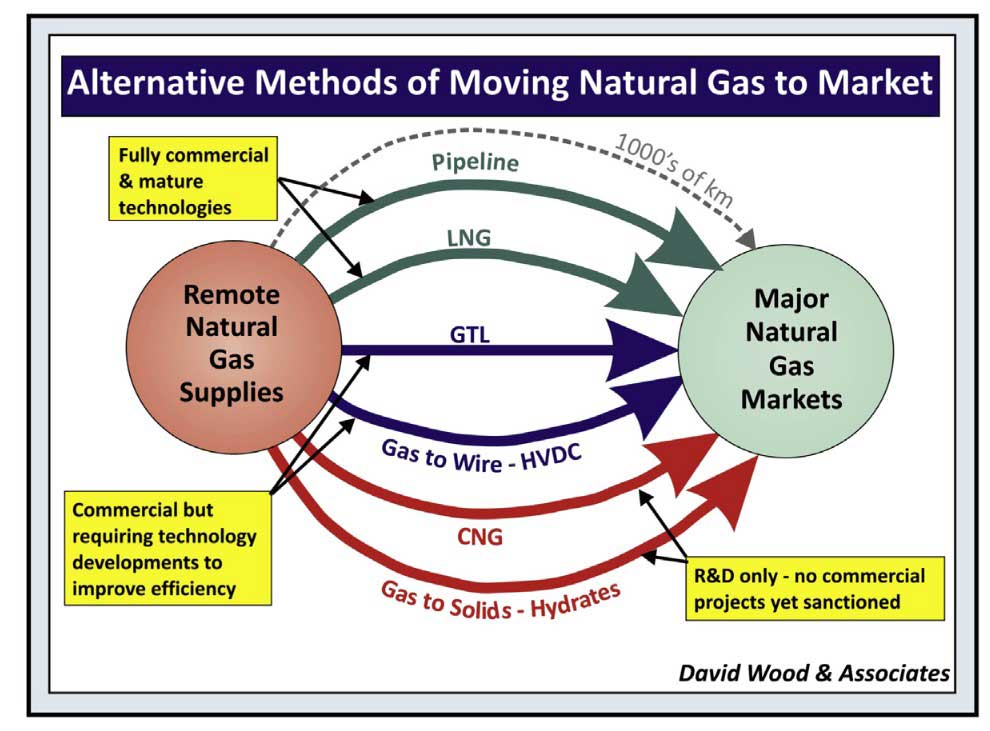
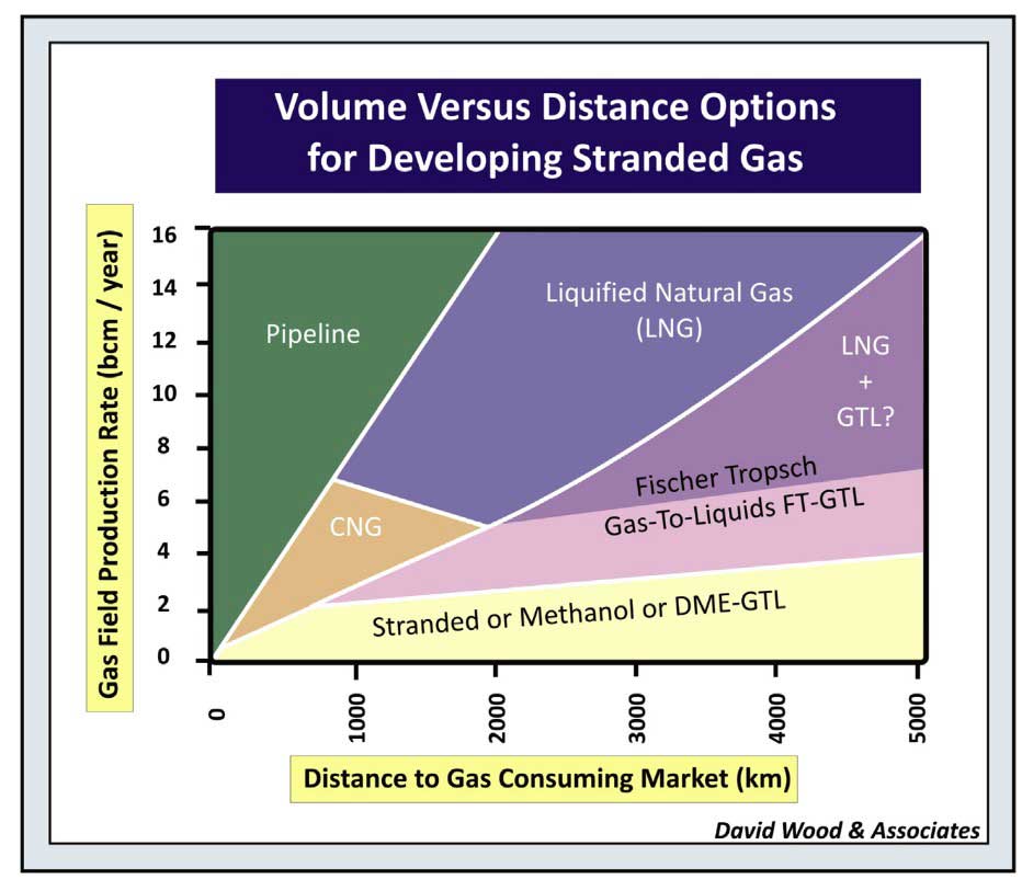
However, most of them are not fully matured to the extent for commercialization, and would require improvements in order to compete with existing technologies. On the other hand, selection of existing technologies is dependent on the distance to consumer markets and the gas field production rates (see Picture 2).
Stranded gas is currently transported to markets primarily via two long-established technologies:
- some 70 % of gas traded internationally is exported by pipeline;
- the remaining 30 % by liquefied natural gas.
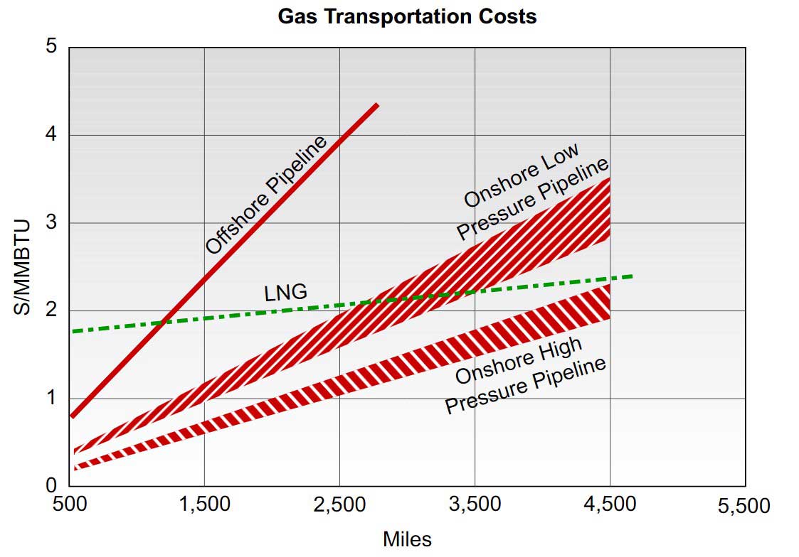
Picture 3 shows that LNG cost becomes competitive to pipeline gas for long-distance transport. As can be seen from Picture 3, for short distances, gas pipelines are usually more economical. LNG is competitive for long-distance routes, particularly those crossing oceans or long stretches of water, since construction of undersea pipelines is cost prohibitive (Mokhatab et al., 2006). For offshore stranded gas, LNG can be competitive when the offshore pipeline is less than 700 miles. For onshore pipelines, the breakeven point is about 2 200 miles (Mokhatab and Purewal, 2006).
When natural gas is cooled to approximately -162 °C or -259 °F at atmospheric pressure, the condensed liquid is LNG. The volume reduction is about 1/600th the volume of natural gas at the burner tip. The more condensed form of LNG allows transport using cargo ships or trucks. For long-distance transport, the gas pipeline option would require large diameter pipes and gas recompression facilities to overcome the transmission pressure drop, which are very costly.
The LNG option offers economics, flexibility, and security of supply advantages over gas pipeline and other technology alternatives. Many countries in Europe and Asia are embracing LNG for these reasons, even though large volumes of gas from Russia, North Africa, and the Middle East could satisfy their domestic energy demands through existing and planned pipeline connections. Today, with the increase in gas supply from the nonconventional gases, export from North American to the Asian countries is imminent. The share of the international natural gas trade as LNG is expected to increase in the coming decades.
LNG characteristics
Basic properties
A basic knowledge of LNG must begin with an examination of its chemical and physical properties, which is a prerequisite for accurately assessing potential LNG safety hazards and risks.
The properties of LNG vary with its composition, which depends on the reservoir source of the original gas and its processing/fractionation history. While LNG is predominately methane (about 87 mole % to 99 mole %), its composition also includes other higher hydrocarbons, typically, the C2 to C4 and heavier, nitrogen and trace amounts of sulfur (less than 4 ppmv), and CO2 (50 ppmv; see Table 1).
| Table 1. Typical Composition of LNG from Various Liquefaction Plants | ||||||
|---|---|---|---|---|---|---|
| Component mole % | Nigeria LNG | Arun LNG | Brunei LNG | Oman LNG | Atlantic LNG | Kenai LNG |
| Methane | 87,9 | 88,48 | 89,4 | 90 | 95 | 99,8 |
| Ethane | 5,5 | 8,36 | 6,3 | 6,35 | 4,6 | 0,1 |
| Propane | 4 | 1,56 | 2,8 | 0,15 | 0,38 | 0 |
| Butane | 2,5 | 1,56 | 1,3 | 2,5 | 0 | 0 |
| Nitrogen | 0,1 | 0,04 | 0,2 | 1 | 0,02 | 0,1 |
| (ILEX Energy Consulting, 2003) | ||||||
LNG is an odorless, colorless, and noncorrosive cryogenic liquid at normal atmospheric pressure. When LNG is vaporized and used as natural gas fuel, it generates very low particle emissions and significantly lower carbon emissions than other hydrocarbon fuels. The combustion products from LNG contain almost no sulfur oxides and a low level of nitrogen oxides, which makes LNG a clean source of energy.
LNG is nontoxic. However, as with any gaseous materials, natural gas release from LNG can cause asphyxiation due to lack of oxygen in an unventilated, confined area, and can be ignited if mixed with the right concentrations of air.
The boiling point of LNG varies with its composition, typically -162 °C (-259 °F). The density of LNG typically falls between 430 kg/m3 and 470 kg/m3 (3,5 to 4 lb/US gal), which is less than half the density of water. LNG, if spilled on water, floats on top and vaporizes rapidly because it is much lighter than water. Initially LNG vapors are heavier than air and will stay near ground level. However as LNG vapors begin to be warmed up by the surroundings and reach temperatures of approximately -166 °F, the density of the vapors is lighter than air and the vapors become buoyant. Cold LNG vapors (below -166 °F) are more likely to accumulate in low areas until the vapors warm up. A release of LNG in an enclosed space or low spot will tend to displace air, making the area hazardous for breathing.
Vapors released from LNG, if not contained, will mix with surrounding air and will be carried downwind, which may create a vapor cloud that may become flammable and explosive. The flammability limits are 5 % and 15 % by volume in air. Outside of this range, the methane/air mixture is not flammable.
When fuel concentration exceeds its upper flammability limit, it cannot burn because too little oxygen is present.
This situation exists, for example, in a closed, secure storage tank where the vapor concentration is approximately 100 % methane.
When fuel concentration is below the lower flammability limit, it cannot burn because too little methane is present. An example is leakage of small quantities of LNG in a well-ventilated area. In this situation, the LNG vapor will rapidly mix with air and dissipate to less than 5 % concentration (Foss et al., 2003).
Vaporized LNG has the same thermal characteristics as natural gas. In well-ventilated areas, natural gas burns with a low laminar burning velocity and has high ignition energy relative to other hydrocarbon fuels. Natural gas vapor in open areas has not produced unconfined vapor cloud explosions (UVCE), which are more prevalent with higher hydrocarbons.
Whether any flammable vapor cloud merely burns back to the vapor source or undergoes an explosion depends on many factors:
- the chemical structure of the vapor molecules;
- the size and concentration of the vapor cloud;
- the strength of the ignition source;
- and the degree of confinement of the vapor cloud.
The conditions needed to produce an unconfined vapor cloud explosion of natural gas are generally not present in an LNG facility, so such explosions should not be considered as potential hazards.
Thermodynamic properties
Knowledge of the LNG phase behavior and thermodynamic properties is required for the successful design and operation of LNG production plants and handling facilities. Therefore, it is important to apply appropriate models within a thermodynamic modeling framework to predict, describe, and validate the complex phase behavior of LNG mixtures. In this case, equations of state, which can both qualitatively and quantitatively predict the complex types of phase behavior found in real systems, are usually the primary choice.
Phase behavior prediction and modeling of LNG systems with equations of state will be described in Appendix 2.
LNG safety
The LNG industry has an excellent safety record, as a result of several factors. First, the industry has been developed to ensure safe and secure operations, from engineering to technical competency of personnel. Second, the physical and chemical properties of LNG are well understood and the plant designs are well proven through many years of operation. Third, the standards, codes, and regulations that have been developed for the LNG industry ensure safety and are continuously evolving and improving.
Chapter 9 explores hazards associated with and safety features designed for the unusual characteristics of LNG.
Units and conversion factors
The metric ton is commonly used to account for quantities of LNG. LNG production is commonly expressed in million metric tons per year. The units often used are MMTPA, MTPA, tpy, or a more SI conforming expression Mt/a, which stands for mega but can also be read as million tons per annum.
The various conversion factors for common units in the LNG business are given in Table 2.
| Table 2. LNG Conversion Factors | ||||||
|---|---|---|---|---|---|---|
| Frequently Used Conversions for Natural Gas and LNG | ||||||
| To | Billion Cubic Meters of Natural Gas | Billion Cubic Feet of Natural Gas | Million Tons of LNG | Trillion Btu | ||
| From | Multiply By | |||||
| 1 Billion Cubic Meters of Natural Gas | 1 | 35,315 | 0,76 | 38,847 | ||
| 1 Billion Cubic Feet of Natural Gas | 0,028 | 1 | 0,022 | 1,100 | ||
| 1 Million Tons of LNG | 1,136 | 46,467 | 1 | 51,114 | ||
| 1 Trillion Btu | 0,026 | 0,909 | 0,02 | 1 | ||
| Typical Liquid-Vapor Natural Gas and LNG Conversions* | ||||||
| To | Liquid Measures | Vapor Measures | Heat Measure | |||
| Metric Ton LNG | Cubic Meter LNG | Cubic Foot LNG | Cubic Meter Natural Gas | Cubic Foot Natural Gas | Btu* | |
| From | Multiply By | |||||
| 1 Metric Ton LNG | 1 | 2,193 | 77,445 | 1,316 | 46,467 | 51,113,806 |
| 1 Cubic Meter LNG | 0,456 | 1 | 35,315 | 600 | 21,189 | 23,307,900 |
| 1 Cubic Foot LNG | 0,0129 | 0,0283 | 1 | 16,99 | 600 | 660,000 |
| 1 Cubic Meter Natural Gas | 0,00076 | 0,001667 | 0,058858 | 1 | 35,315 | 38,847 |
| 1 Cubic Foot Natural Gas | 0,000022 | 0,000047 | 0,001667 | 0,02832 | 1 | 1,100 |
Conversion Factors:
- 1 million metric tons/year = 1,316 billion cubic meters/year (gas) = 127,3 million cubic feet/day (gas);
- 1 billion cubic meters/year (gas) = 0,760 million metric tons/year (LNG or gas) = 96,8 mcf/day (gas);
- 1 million cubic feet/day (gas) = 10,34 million cubic meters/year (gas) = 7,855 metric tons/year (LNG or gas) (US DOE/FE-0489, 2005).
These are the thumb rules of conversion of LNG; the actual factors would vary based on the composition of LNG.
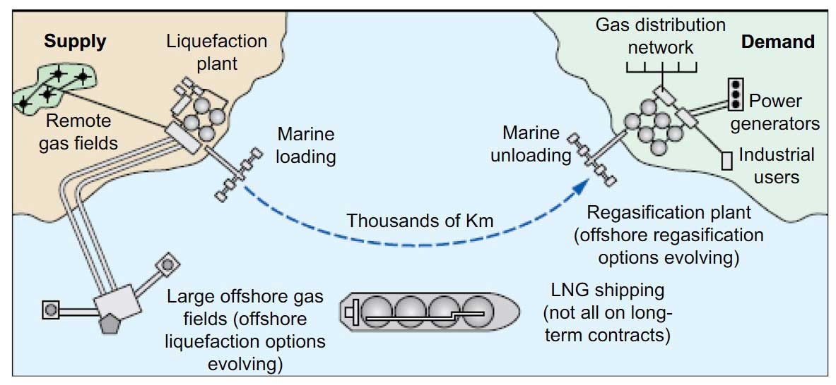
Traditional LNG supply chain
To make LNG available for use in a country, energy companies must invest in a number of different facilities that are highly linked and dependent upon one another. The major components of the traditional LNG supply chain, including pipeline connections between the stages, include the following as shown in Picture 4.
LNG production plant
A typical scheme for an LNG production plant designed to produce LNG from a sour gas feed is shown in Picture 5. The process and utility requirement design depends on site conditions, feed gas conditions, compositions, and products specifications.
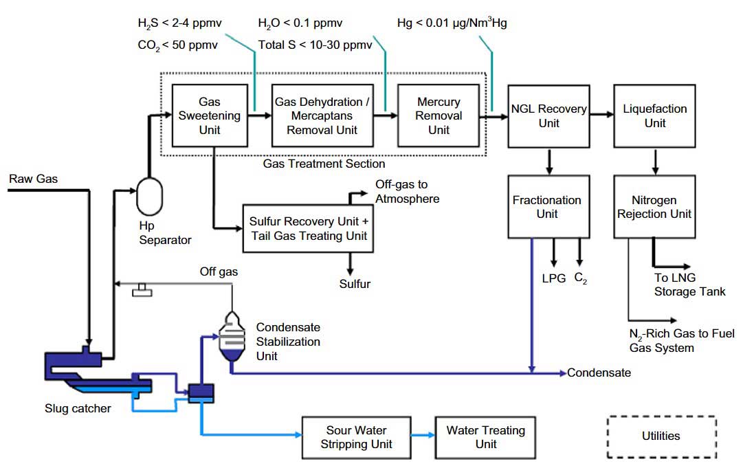
Feed gas conditioning
In a typical scheme, field production upon arrival at the processing plant is first separated in a slug catcher, which removes the liquids and routes the gas to a high pressure (HP) separator. The liquids are flashed to a medium pressure separator, where the hydrocarbon liquids are further separated and fed to the condensate stabilizer. The liquids are fractionated in the stabilizer, producing a bottom condensate product consisting of the C5 and heavier hydrocarbons. The condensate is stripped with steam to remove its H2S content and has to meet an RVP (Reid Vapor Pressure) specification of 12 psia, which are required for transport and storage.
Vapors from the medium separator and stabilizer column overhead are compressed and recycled back to the HP separator. The vapors then flow to the Gas Sweetening Unit, GSU (also called Acid Gas Removal Unit, AGRU), in which H2S and CO2 are removed. H2S is removed by an amine solvent to meet the total sulfur product specification, typically 4 ppmv. CO2 is removed to 50 ppmv to avoid CO2 freezing in the main exchangers in the liquefaction plant.
Carbonyl sulfide (COS) and mercaptans (R-SH) contribute to the sulfur contaminants and must also be removed. The acid gas from the regeneration section is sent to the Sulfur Recovery Unit (SRU), typically consisting of a Claus unit and a Tail Gas Treating Unit (TGTU). The off-gas from the TGTU absorber is incinerated.
The sweet gas from GSU is required to be dried in a dehydration unit utilizing molecular sieves technology to below 0,1 ppmv to avoid hydrate formation in the NGL recovery unit. The sweet gas is saturated with water, and in hot climate operation the water content can be significant. It is more energy efficient and cost effective to chill the sweet gas first, removing the bulk of water before passing to the molecular sieve units. The molecular sieve can also be designed to remove mercaptans from the dried gas to meet the sulfur specification.
Typically, traces of mercury are present in the feed gas, which must be removed by mercury removal beds to less than 10 nanograms per cubic meter to avoid mercury corrosion in the downstream cryogenic exchanger.
NGL recovery
The dried gas is routed to a Natural Gas Liquid (NGL) recovery unit, which is designed to remove and recover the C2+ or C3+ hydrocarbons and produce a lean gas for liquefaction. Removal of the NGL components would eliminate the need for a scrubber column in the liquefaction plant, which typically is used to remove aromatics and heavy hydrocarbons to avoid waxing in the main exchanger.
The NGL recovery unit can be designed for ethane recovery to produce an ethane product that can be fed to an ethylene cracker in a petrochemical complex. The NGL components, the C3 to C5+ liquids, are valuable marketable products. The NGL components are fractionated into individual products for sales. Propane and butane are exported as separate products, or a combined propane-butane mix product. C5+ and heavier components can be exported for gasoline blending. If mercaptans were present in the feed gas, they would show up in the C5+ liquids, which must be treated to meet the liquid’s sulfur specification.
Liquefaction
The lean gas leaving the NGL recovery unit enters the liquefaction unit that chills and liquefies the gas in a refrigeration process. Liquefaction technology is based on the principle of a refrigeration cycle, where a refrigerant by means of successive expansion and compression removes the heat content of a gas stream, by rejecting to the ambient air or cooling water.
The refrigerant may be part of the:
- natural gas feed (open-cycle process);
- or a separate fluid continuously recirculated through the liquefier (closed-cycle process).
After liquefaction of the natural gas, a nitrogen rejection unit is required if the nitrogen content is above the commercial specification of LNG, typically at 1 mole %. The low nitrogen content in the LNG product is required to avoid low liquefaction temperatures, to reduce the nitrogen content in the boil-off such that it can be used as fuel gas, and to reduce the risk of rollover in the storage tanks in the terminals when delivered to the customers. Rollover occurs in a weathered tank, where there is rapid mixing of stratified layers within an LNG tank causing sudden release of very high levels of boil-off gas within a short period.
Typically, LNG from the liquefaction plant is let down in pressure in a flash drum to close to the LNG storage pressure, and nitrogen, being the lighter component, is flashed off and removed. The nitrogen-rich vapor is compressed and recovered as fuel gas. The flashed liquid is pumped into the storage tanks for export. This end-flash process is well suited to feed gases with nitrogen content of up to 2 mole % (Vovardet al., 2011). However, with a high nitrogen feed gas, the simple end-flash process is not sufficient and an additional fractionation step is required. If not removed, the high nitrogen content would lower the liquefaction temperature, and would increase the power consumption by the refrigeration unit. In addition, the nitrogen content of the flash gas and boil-off gas would be higher, which may not meet the heating value specification of fuel gas. Therefore, there is a justification to remove the nitrogen content either before or during liquefaction.
Nitrogen removal by cryogenic separation process is the proven nitrogen removal process for LNG production. The other alternatives such as pressure swing adsorption or membrane technology are not cost competitive in meeting the very low nitrogen specification (Finn, 2007; Garcel, 2008).
Feed gas conditioning, NGL recovery, liquefaction, and nitrogen removal technologies will be addressed in more detail in subsequent chapters.
Liquefaction plant types
Natural gas liquefaction plants can be classified into large base load, peak-shaving, and small- to medium-scale plants depending on their sizes and functions.
Most of the base load plants are located in large gas reservoirs in Asia, Australia, the Middle East, and West Africa and are mega projects. These base load plants supply natural gas as LNG from the natural gas producers to the consumer nations. Base load plants typically consist of one or multiple trains. The liquefaction train size has steadily increased over the last 40 years with capacities of over 4 million tons per annum now being conventional.
Single trains of 7.8 MTPA are now operational in Qatar.
Peak-shaving plants, which are commonly used to balance the fluctuation in natural gas supply and demand during summer and winter months, are small in size, typically up to 0,1 MTPA. They are used to liquefy and store excess gas production and to provide extra capacity during peak demand periods.
As the large reservoirs are slowly being depleted, smaller reservoirs in remote locations are now being explored. These opportunities have prompted some market players to evaluate mid-scale LNG technology applications. Mid-scale LNG plants, ranging from 0,3 to 1,5 MTPA, are applicable for medium-sized onshore and offshore gas fields (Finn et al., 2000).
Small-scale LNG plants, with capacities as low as 0,01 MTPA, are economically viable when excess capacity of gas pipeline is available. LNG can be distributed by LNG trucks to customers that are located in remote areas inaccessible by pipelines or as an emergency fuel backup. LNG can also be used to replace diesel fuel in refuge trucks, public transports, and drilling rigs operation. The use of LNG instead of diesel fuel would significantly reduce emissions and lower fuel costs. The small-scale LNG units have also been installed recently on large LNG carriers to reliquefy boil-off gas and reduce shrinkage of the LNG during the shipping voyage.
LNG train size
Base load LNG plants are designed along the train concept. The train concept allows the plants to continue production when one of the trains is down for maintenance or unexpected shutdown. The train concept has evolved to meet market demands, delivery flexibility, and shipping logistics. Train size is determined by limitations on critical equipment, mainly proven gas turbine drivers size sand liquefaction heat exchangers capacity (Smaal, 2003). However, for the most part, equipment developments have kept pace with the increases in train capacity.
The trend within the LNG industry has been to push the limits of LNG production capacity of a single train. In fact, many base load liquefaction plants built since 2004 have been plagued by high capital cost inflation. In spite of these cost obstacles the large IOCs, NOCs, and technology providers in the industry continue to increase the size of single liquefaction trains. Larger single train size tends to lower the unit cost of production, helping to make it competitive in the marketplace (Wood and Mokhatab, 2007a).
One of the main cost components in a liquefaction plant is the refrigeration compressor turbine driver. With the advances in larger and more efficient gas turbine drivers, producing more LNG in a single train can justify the incremental increase in capital cost. The cost of the support facilities, such as utility and offsite, are not much affected by the larger train size. The larger train would require more frequent shipment, but overall, this approach will improve the overall project economics (Durr et al.,2005). However, to fully realize the cost advantages of the larger trains, a high plant reliability and availability must be maintained; design must be robust and must be provided with sufficient spare equipment in case of equipment shutdown.
LNG technology has undergone a significant improvement in the past decade versus its 50 year history (see Picture 6). It took 30 years for the industry to progress from less than 0,5 MTPA capacity trains in Arzew, Algeria, to 3 MTPA trains in the late 1990s in Bonny, Nigeria. In the past decade, several trains in the 4+ MTPA range came on-stream such as the Damietta LNG plant in Egypt producing about 4,8 MTPA of LNG in 2004 and the 7,8 MTPA trains of the Qatargas II plant in 2009. This steady increase in train capacity has enabled the industry to achieve economy of scale benefits that at least have managed to offset the rising capital costs the industry has experienced over the past decade.

In the past few years liquefaction plants in the following countries have come on-stream with liquefaction train capacities shown in brackets:
- Australia NWS train 5 (4.4 MTPA – 2008);
- Russia Sakhalin (4.8 MTPA – 2009);
- Indonesia Tangguh (3.8 MTPA – 2009);
- Yemen (3.4 MTPA – 2009);
- Peru (4.4 MTPA – 2010);
- Australia Pluto (4.3 MTPA – 2012);
- Angola (5.2 MTPA – 2013).
Several large liquefaction plants are under construction in Australia (and Papua New Guinea) and are due to come on-stream in the 2015 to 2017 period. In addition several liquefaction plants are now in the advanced planning stages in North America (United States and Canada), planning to export vast resources of shale gas unlocked by recent advances in fracture stimulation technology. The vast natural gas resources found recently on offshore East Africa are also attracting interest from LNG suppliers and buyers for potential new projects. The natural gas industry therefore seems destined to continue its significant growth over the coming decades.
During development of an LNG business, there has been a continuing debate on an optimum size of an LNG train (Liu et al., 1992; Hunter et al., 2004).
Many factors should be considered when choosing an optimal train size for an LNG project (Avidan et al., 2001), such as:
- Gas deliverability from the gas field;
- Market demands and LNG delivery buildup profile;
- Overall production, storage, and shipping logistics;
- Commercially proven equipment sizes;
- Capital and operating costs;
- Operational flexibility and reliability.
The main objective is maximizing the overall project rate of return, considering all these factors. For an LNG supply chain, it is not enough to optimize only the liquefaction facilities without considering both upstream and downstream facilities. Optimization of these parameters, from production to delivery, must be considered.
For example, production can be limited by one or several factors, such as LNG storage capacities in the export and import terminals, availability of LNG carriers and sizes, ship travel speeds, weather conditions, customer specifications, LNG pricing that must address spot market demands or long terms contracts, and political situations.
Many of these variables are statistical in nature, thus the most appropriate too is a “Mont Carlo” type simulation (Coyle et al., 1995), which is an event-driven simulator addressing multiple variables at the same time.
LNG loading
Depending on the customer’s demand, LNG can be loaded into LNG trucks at a truck loading bay and/or to LNG ships at the jetty. During LNG truck loading, the LNG is pumped to the truck by means of truck loading pumps. The LNG is routed via the truck loading line and loading hose to the truck. For LNG ship loading, the LNG that is stored in storage tanks is pumped to the product jetty. At the jetty, LNG is loaded onto LNG ships for export The time period during which the ship is berthed and the loading operation is under way is termed the loading mode.x.
For ship loading, the loading rate is driven by keeping the ship loading time as short as possible due to the high cost of ship demurrage (Coyle et al., 2003). Two or three liquid loading arms are required depending on the loading rate and capacities of the loading arms. The loading lines are kept cold during the holding operation when there is no loading activity by continuously circulating a small stream of the plant LNG rundown to the jetty head and back to the storage tanks.
This is done to keep the loading system cold and gas free at all times, to avoid thermal stress and to allow immediate startup of ship loading after arrival of an LNG carrier. One additional arm is dedicated to handling displaced gas from the ship’s tank, flashed gas due to the pressure difference between the ship and the storage tanks, and boil-off gas (BOG) from heat gain during ship loading. In scenarios of short jetty lines, the ship BOG generation is relatively minor and can be returned to onshore facilities where it can be recovered.
However, at some locations the jetty needs to be extended several kilometers to reach ship berths at shallow ports or coastlines (Kotzot, 2003). In this scenario, BOG management poses some challenges. Long jetties, which imply long LNG loading lines, result in higher BOG generation rate due to higher pumping energy and heat leakage through piping and vessels. Moving large volumes of low-pressure BOG across long jetties is fairly costly. Therefore, it is generally uneconomical to recover BOG from long jetties.
Historically some BOG was flared during LNG ship loading operations. However, as environmental regulations become more stringent, flaring of BOG during ship loading is not permitted. There are various BOG recovery options suitable for long jetties. These may include compressing the BOG back to LNG plant for recovery, in-situ reliquefaction, and in-situ power generation. In each LNG project, the feasibility of the alternatives should be considered from perspectives of environmental impacts, operational safety and efficiency as well as marine operational limitations (Huang et al., 2007).
Note that the right choice of insulating the pipeline from storage to ship can minimize heat gain and boil-off gas. Many insulation choices have come to the market in recent years for use in the cryogenic LNG piping application. The materials/techniques most commonly used are mechanical insulation such as glass foam and polyisocyanurate, “powder” insulations such as:
- aerogel;
- perlite;
- izoflex;
- and high vacuum insulation.
However, many factors need to be considered for each LNG pipeline application and installation to determine the most efficient insulation that will provide the best solution (Kitzel, 2008).
LNG transportation
The next step in the LNG supply chain is transporting the liquefied natural gas to the regasification facilities. Primary modes of transport are by ships and trucks.
By ship
LNG is transported by specialized ships, LNG carriers, with insulated double-hulled tanks, designed to contain the cargo slightly above atmospheric pressure at a cryogenic temperature of approximately -259 °F (-169 °C). Typically, the storage tanks operate at 0,3 barg with a design pressure of 0,7 barg.
The tank design ensures integrity of the hull system and provides insulation for LNG storage. Because the insulation cannot prevent all external heat from reaching the LNG, some of the liquid boils off during the voyage. LNG vaporization is not homogenous: components with the lowest boiling point (nitrogen and methane) tend to evaporate more readily than heavier components. This phenomenon is called ageing or weathering and its consequence is that the LNG composition becomes heavier, and the heating value and Wobbe Index of LNG increases over time.
The boil-off gas, typically at the rate of about 0,10 % to 0,15 % of the ship volume per day, must be removed to keep the ship’s tanks at a constant pressure. The boil-off gas can be used as fuel in the ship’s dual fuel engines or burned in the boilers to produce steam or reliquefied and returned to the cargo tanks, depending on the design of the vessel. BOG reliquefaction can eliminate LNG shrinkage during long voyages and maintain the cargo’s composition.
Containment systems for LNG carriers
The fundamental difference between LNG carriers and other tankers is the cargo containment and handling system. There are four LNG containment systems; two freestanding solid type structures, and two nonfreestanding (membrane) type designs.
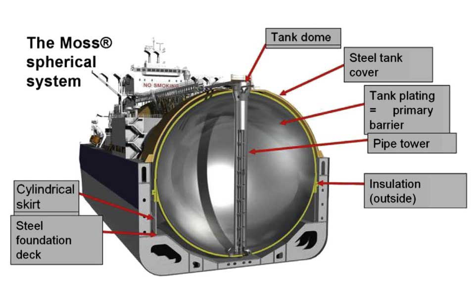
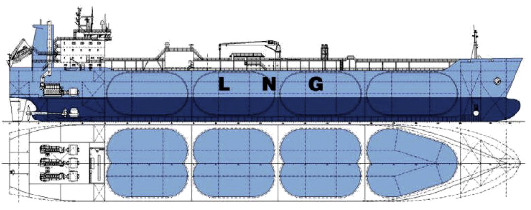
Freestanding tanks. The freestanding or independent tanks are self-contained, usually spherical (developed by Moss Maritime of Norway) or prismatic in shape (designed by Conch International Methane Ltd), and made of aluminum alloy or 9 % nickel steel with layers of insulation on the outside (Pictures 7 and 8). Independent tanks are completely self-supporting and do not form part of the ship’s hull structure. Moreover, they do not contribute to the hull strength of a ship (McGuire and White, 2000). The tanks are welded to cylindrical skirts or otherwise tied to supporters that are welded to the ship structure.
As defined in the IGC Code (International Code for the Construction and Equipment of Ships Carrying Liquefied Gases in Bulk), and depending mainly on the design pressure, there are three different types of independent tanks for gas carriers. These are ones built according to standard oil tank design (Type A), others that are of pressure vessel design (Type C), and, finally, tanks that are neither of the first two types (Type B). All LNG tanks are Type B from the Coast Guard perspective, because Type B tanks must be designed without any general assumptions that go into designing the other tank types. The self-supporting, prismatic Type B (SPB) tank is independent of the ship’s structure and has the advantage over its spherical version of making maximum use of the available cargo space. However, they contribute significantly to weight and cost due to the fact that free-standing prismatic tanks include heavy plates and a considerable amount of bracing to keep the plates from distortingunder hydrostatic load.

Membrane containment systems. Membrane tanks are non-self-supported cargo tanks surrounded by a complete double hull ship structure. The membrane containment tanks consist of a thin layer of metal (primary barrier), insulation, secondary membrane barrier, and further insulation in a sandwich construction (Picture 9). The membrane is designed in such a way that thermal and other expansion or contraction is compensated for without undue stressing of the membrane.
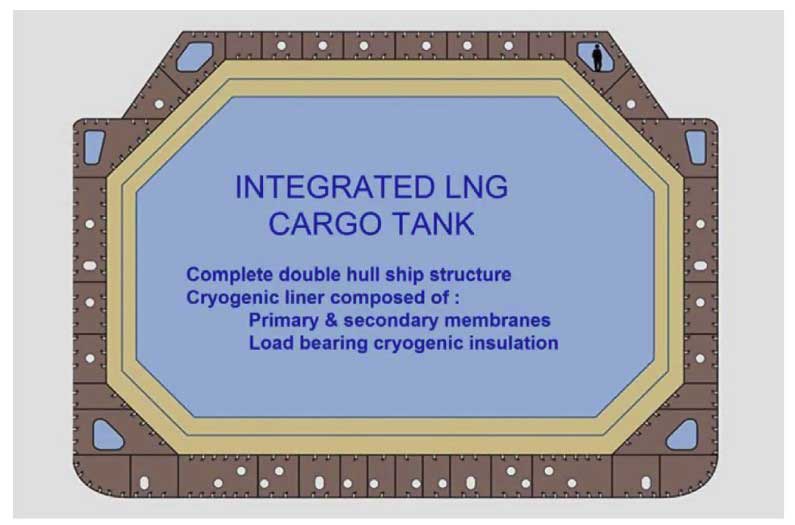
With the membrane design, the ship’s hull, in effect, becomes the outer tank. Insulation is installed thereon, and a membrane placed on the inside to retain the liquid. The inner surface of this “double hull” is either high nickel content (36 %) steel (Invar), offered by Gaz Transport, or 18 % chrome/8 % nickel stainless steel, offered by Technigaz (Pictures 10 and 11).
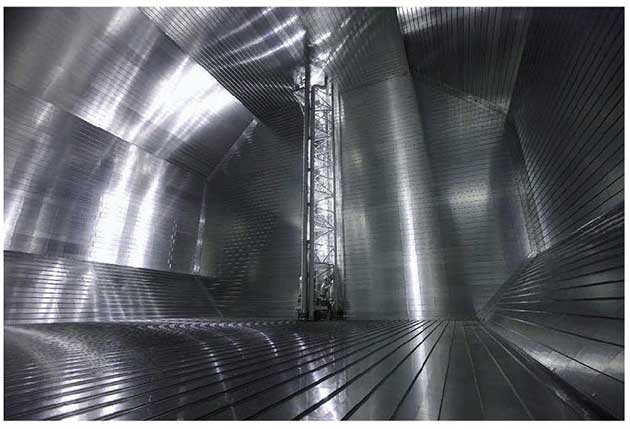
The Gaz Transport membrane containment system (GT NO96) consists of a grillage structure madeof plywood and filled with perlite in order to maintain tightness and insulation. On the other hand, the Technigaz membrane system (TG MARK III) consists of two layers of reinforced polyurethane foam separated by a material called triplex in order to configure an insulation system.

Gaz Transport and Technigaz are now one company, whose latest containment system (Combined System Number One, CS1) incorporates features from the existing GT No 96 and TG Mark III systems. CS1 uses reinforced polyurethane foam insulation and two membranes, the first one 0,7 mm thick made of Invar, the second made of a composite aluminum-glass fiber called triplex. The system has been rationalized to make assembly easier and is prefabricated, allowing quick assembly onboard. However, this design has suffered from secondary membrane leakage problems in some vessels, but established shipyards have decided to maintain production of the GT NO96 & TG Mark III.
Selection of containment systems. Table 3 gives the comparative characteristics of different LNG containment systems. As all cargo tank system designs have proven safe and reliable in service, the choice of cargo tank design is primarily based on economics – price, delivery schedule, and shipyard availability – rather than technical or performance criteria. In the last several years there has been a clear move toward membrane-type carriers, because membrane tanks utilize the hull shape more efficiently and thus have less void space between the cargo tanks and ballast tanks.
| Table 3. Comparative Characteristics of LNG Containment Systems | |||
|---|---|---|---|
| Characteristics | Freestanding Tanks | Membrane Tanks | |
| Prismatic | Spherical | ||
| Safety in event of vessel grounding/collision or other emergency | Compared with membrane system less likelihood of hull damage being transmitted to cargo tanks.More efficient use of cubic space. | Safest system in event of grounding or collision-tank structure independent of hull and most void space between vessel hull and cargo tanks.Spherical tanks can be pressurized for emergency discharge in case of cargo pump failure. | Damage to hull of vessel may be more easily transmitted to tank structure than with freestanding tanks.Membrane systems are also more liable to damage or puncture due to causes such as surging of cargo in tank and entry of tank for inspection or repair. |
| Reliability of containment system | Most ship years operating experience and most experience without primary barrier failure.Structure can be analyzed and risk of fatigue failures minimized.Tanks can be constructed and 100 % inspected prior to installation in vessel. | Tank system easiest to analyze structurally; therefore can be made most reliable. | Structure cannot easily be analyzed and therefore difficult to assure absence of fatigue failures. This could potentially lead to costly off-hire and repair time over the project life. |
More than three-quarters of the new LNG ships constructed in the decade 2001 to 2011 were of the membrane design due to their cargo capacity and capital cost advantages. However, self-supporting tanks are more robust and have greater resistance to sloshing forces Sloshing is liquid motion within a tank that can be produced by wave-induced ship motions (e.g., ships at sea). Sloshingmay resonate with structural frequencies and can impose stress loads on the internal tank structure, which may result indamage of the membrane structure.x which is an important design consideration for offshore storage.
LNG carrier cargo capacities and ship dimensions
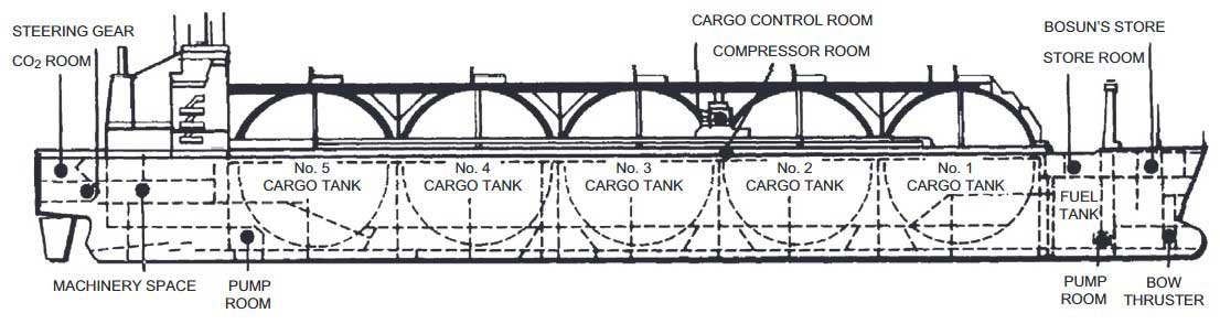
LNG ships vary in size from less than 30 000 m3 to some 265 000 m3 cargo capacity but the majority of modern vessels are between 125 000 m3 and 140 000 m3 capacity (58 000 to 65 000 tonnes). The industry standard some decades ago became the 125 000 m3 LNG ship, which usually had five cargo tanks, each with a capacity of about 25 000 m3 (Picture 12).
New larger LNG ships called Q-Flex (with capacity of about 216 000 m3 of LNG) and Q-Max (with capacity of up to approximately 265 000 m3 of LNG) were built to service long-distance supply chains from the large liquefaction trains commissioned in Qatar between 2009 and 2011 Q-Flex stands for Qatar and flexibility – a design enabling delivery to about 65 % of existing LNG ports; Q-Max stands forQatar and the maximum vessel size that could dock at the Qatar port facilitydthese may have access to approximately 50 % of current LNG ports.x.
These LNG carriers are propelled by slow-speed diesel engines, which are more efficient, easier to maintain and operate, and more environmentally friendly than traditional steam turbine drivers. These ships are also equipped with an on-board reliquefaction system that prevents losses of boil-off gas. While the Q-Flex and Q-Max LNG vessels are beyond the capacity of some ports, nearly half of the world’s existing LNG terminals can, or with modifications could, accommodate these ships.
Typical dimensions of LNG ships quoted by Lee et al. (2008) are:
- Cargo Volume 138 000 to 173 000 cubic meters: length overall 277 to 290 meters; depth 26,0 to 26,5 meters, breadth 43,3 to 45,8 meters, number of tanks 4; single or twin propeller systems.
- Cargo Volume 210 000 cubic meters (Q-flex): length overall 315 meters; depth 27 meters, breadth 50 meters, number of tanks 5; twin propeller systems.
- Cargo Volume 263 000 cubic meters (Q-max): length overall 345 meters; depth 27 meters, breadth 55 meters, number of tanks 4; twin propeller systems.
Small LNG ship
The recent LNG logistic chain research indicates a new market segment that requires the use of smaller LNG ships and smaller LNG receiving terminals. The shortage of clean fuel promotes the utilization of LNG for small and medium scale applications in developing countries (Mak et al., 2013). Two small LNG carriers with 2 500 m3 capacity have been in service since 2004 for coastal LNG transportation in Japan. Currently, a Japanese shipyard is building an LNG carrier with 19 000 m3 capacity. In Norway, coastal transportation of LNG consisting of small LNG ships with 1 000 m3 capacity is being used to supply fuel to areas lacking gas pipelines.
Unlike the larger vessels, the containment systems in smaller ships are designed with the independent Type C tanks, according to pressure vessel codes. The vessels were originally developed for ethylene carriers and can be upgraded to meet the LNG terminal requirements in an offshore environment. The type C tanks are typically not economical for large vessels due to the high cost due to wall thickness. On the other hand, the type C tanks are easy to fabricate and do not require a secondary barrier because of the pressure vessel design. The tanks can be fabricated outside the shipyard, making them more cost competitive.
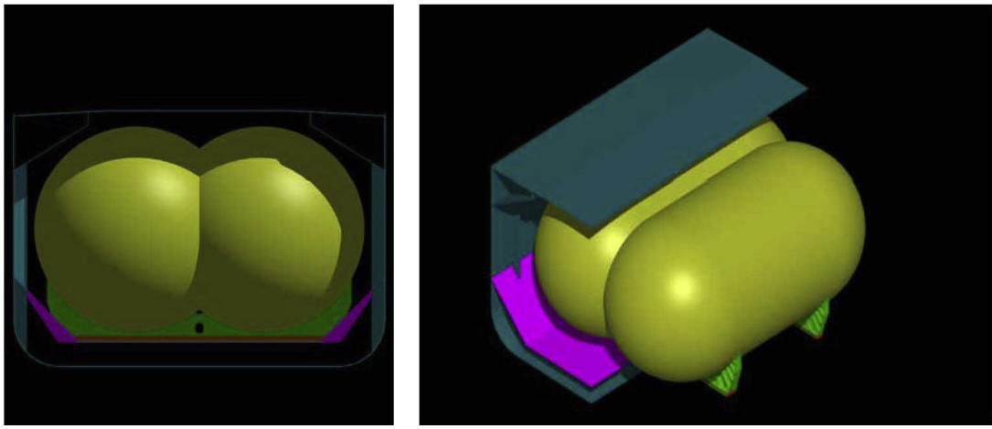
A conceptual design of a 30 000 m3 LNG carrier using the IMO Type C tanks design is illustrated by TGE in Picture 13. The Bilobe tank arrangement is shown in Picture 14.
The containment can be designed for higher design pressures of 4 to 8 barg, which can be used to suppress BOG generation. In fact, some of the small carriers are not equipped with a BOG handling system, which is the simplest way to manage BOG by allowing pressure to increase during the journey. However, storage tanks in the receiving terminals must also be designed for high-pressure storage compatible with the ship, in order to avoid BOG losses during unloading.
The LNG industry is currently experiencing increasing activities for spot LNG cargoes. The introduction of small LNG ships will provide the flexibility and efficiency to accept and deliver smaller LNG cargoes expediently.
LNG ship propulsion systems
Traditionally LNG carriers use a boiler and steam turbine propulsion system that can consume the boil-off gas during transport. On the other hand, most of the ocean-going freight vessels are fitted with high efficiency two-stroke slow speed diesel (SSD) engines. Many new LNG ships built in the past decade have moved away from the traditional less efficient steam propulsion system. Recent high fuel costs may have made alternative propulsion systems more attractive (Lee et al., 2008).
Dual fuel diesel electric (DFDE) propulsion system: Offers high fuel efficiency and freedom of fuel choice between fuel oil and BOG from the LNG cargo tanks. The DFDE system is typically implemented with electric propulsion systems requiring high capacity electric switch gear, frequency converters, and electric motors, which require a crew with special skills to maintain. Compared to steam engines, the maintenance costs of the many cylinders involved in the typical four-stroke engine are higher.
For the large fleet of LNG carriers built for Qatar’s Nakilat with more than 210 000 m3 capacity, two-stroke slow speed diesel engines and onboard BOG reliquefaction system are used. The diesel engines are the same as those of most of commercial ships, with proven performance and reliability. The onboard reliquefaction system is ideal for long voyages avoiding boil-off gas losses. However, when liquid fuel prices are higher than LNG prices, the operating cost of this propulsion system will be higher, as they are unable to use the boil-off gas. An option to overcome this drawback is to use high-pressure gas injection two-stroke SSD engines. However, such propulsion systems have not yet been applied to LNG carriers.
There are other potential propulsion systems that are yet to be proven in LNG carriers.
Gas turbine propulsion systems using onboard BOG: Proven drivers for refrigeration system and for propulsion. They are energy efficient especially in combination with steam turbines in a combined cycle power plant. The gas turbines can use dual fuel and are easy to maintain and operate. Gas turbines can be used for power generation for the propulsion system, or used for direct mechanical drive for the refrigeration compressors in FLNG vessels.
High pressure steam turbines: Have the ability to improve the fuel efficiency over the conventional steam turbines. However, operating a high pressure steam system requires high quality water makeup to reduce boiler blowdown. The cost of the demineralization system and the weight of the boiler system add costs to the ship system. The fuel efficiency of the high pressure steam system, unless it is a supercritical pressure design, is no more than the diesel engines or the gas turbines. It is unlikely that a high pressure steam system will be adopted in an LNG carrier propulsion system.
All propulsion systems include a gas combustion unit (GCU) for the disposal of excess BOG to avoid pressure buildup in the cargo tanks. The use of the GCU is typically required during the ship loading and unloading operations when the fuel demand is low or during the ship cool-down operation when excess boil-off gas is generated.
LNG ships for arctic service
The expected increase in the exploitation of gas fields in arctic, subarctic regions of Russia, and other Northern areas will precipitate the development of arctic LNG shipping. Ships navigating in ice areas perform quite differently due to ice resistance as compared to their open sea operations The presence of first year and multiyear ice imposes additional loads on the hull, propulsion system, and appendages.x. Therefore, itis a challenge for ship designers to find a design solution that not only optimizes the propulsion performance in open sea but also provides the ship with good ice performance (Lee, 2008).
Over the last five years there has been significant technical development in the ice-class tanker design with potential application to future Arctic LNG ships (Tustin, 2005). The first ice-class LNG vessels are about to enter service for the Sakhalin-II project in eastern Russia. Five new LNG ships will service the liquefaction terminal at Prigorodnoye in Aniva Bay:
- three built in Japan with the Moss-type independent tank and hulls designed to Finnish-Swedish ice class 1B standard;
- two ships built in South Korea, each with different membrane tank design.
All five ships have their propeller and line shafting built to Russian Maritime Register of Shipping (RMRS) ice class LU2 standard and the membrane containment ships also have their ice-strengthened hulls built to that standard (Tustin, 2006). The performance of these vessels will provide an indication of the standards required for a more extensive Arctic LNG carrier fleet to withstand sea ice seasons of 100 days and more.
Plans to build regasification terminals along the St Lawrence River in Canada a few years ago suggest that some LNG ships may have to operate eventually in ice at both ends of their routes. The power installed and the ice class of vessels plying the more challenging Arctic routes, such as to the western Arctic coastline of Russia, will need to be higher unless dedicated ice breaker vessels are commissioned to assist them. Winterization features include low-temperature-proof materials for the deck equipment on the vessels themselves and for the loading and unloading facilities.
The ships will have to withstand severe wave conditions and persistent cold environments. Carriers of membrane containment design will need reinforced tank supports to avoid cargo sloshing damage. Indeed membrane designs will need to prove their reliability in such challenging conditions for arctic service. LNG ships built for dedicated service to the Snohvit LNG facility in Northern Norway (ice free all year) are all of the Moss-type design.
The challenges associated with first-year ice navigation and those with multiyear ice navigation are very different. Multiyear ice is prevalent in the Kara Sea and for year-round navigation requires icebreaker assistance with typical hull structure designed for level ice sheet thickness varying from 120 cm to 170 cm thickness in the summer and autumn seasons and 170 cm to 320 cm thickness (with hummocks) in the winter and spring seasons (Tustin, 2006). Movement in such winter conditions requires very powerful engines (85 to 120 MW), narrower beams, and strong propulsion equipment pushing ice breaking hulls moving at times as slowly as two nautical miles per hour (Scherz, 2006).
Even the highest ice-classed LNG vessels will need to have ice breaker assistance. The vessels and support services will not only be expensive, but the periodic slow speeds along the most challenging parts of their routes will require more tankers to transport similar contract quantities than for ice-free supply chains. Shuttle-tanker methodologies might make sense in some cases; for example, ice-classed tankers to move cargoes past the ice edge either to trans-shipment ports or for ship-to-ship transfer. The reality is that each port and shipping route will probably pose its own challenges and require tailored vessel design solutions (Wood and Mokhatab, 2009).
Picture 15 shows a schematic image of the Arctic LNG Shuttle (ALS) concept that is under development by Hoegh LNG in collaboration with LMG Marin.

Note, low temperatures impact the ship, and the cold, lack of light, and visibility affect the crew.
To help address these challenges, the American Bureau of Shipping (ABS) has produced a guide for vessels operating in low temperature environments. Guidance is provided for the preparation of vessels and other marine structures and their crew for operation in harsh environments (Conachey, 2006).
By truck
Where consumers are located in coastal areas, LNG can be delivered by ship. But when they are located inland, the only viable method is by trucking with mobile equipment such as road trailers (Picture 16), ISO intermodal cryogenic containers, or smaller delivery units.
On the production side, liquefaction of small scattered sources of natural gas or biogases in remote areas would not be economical where there are no close-by users. While the reservoir capacity and life may not justify construction of long pipelines, liquefaction and trucking of LNG presents an economically viable solution.
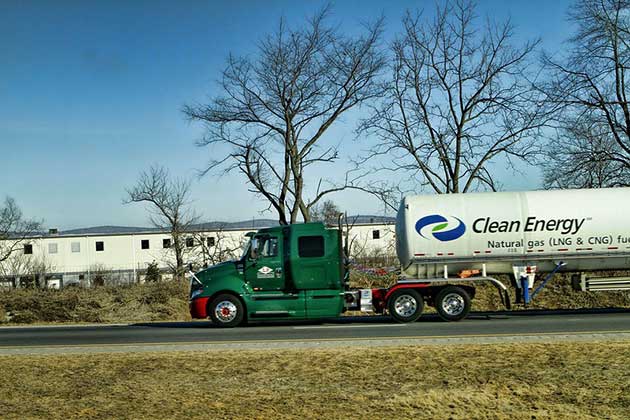
Source: foter.com
On the consumer side, the price of natural gas remains historically low, due to the rapid development of shale gas in North America, which makes natural gas a clean and low cost fuel. LNG trucking is a mature industry. Using specialized, double-skinned vacuum insulated tank trucks, liquefied natural gas can be reliably and safely delivered to LNG refilling stations. At the satellite stations, LNG is unloaded into insulated pressurized storage tanks. Under normal conditions, the vacuum insulated tank can store LNG for long periods without venting (Chrz and Emmer, 2007).
For domestic gas consumers, LNG is pumped, vaporized with ambient air vaporizers, odorized, metered, and delivered to the local pipelines.
Commercial truck fleet operators are now making the switch to the cheaper natural gas from the high priced diesel. Conversion of a diesel engine to use natural gas is simple using a bifuel conversion kit. Such conversions are being done on drilling rigs for shale oil production and can save fuel costs and reduce emissions. Globally, there is a move toward building LNG refilling station infrastructure to reduce energy cost.
The main markets for LNG refueling stations are to serve vehicle fleets, operating directly on LNG onboard. Heavy-duty trucks, busses, refuse vehicles, and frequently operated fleet vehicles such as taxis are typical vehicles with great potential for LNG fueling. Compared to much more traditional CNG systems, LNG fuel has the advantages of high fuel efficiency, lower vehicle dead weight and longer runs because of its high density and low pressure. Centrifugal pumps ensure the delivery of LNG into vehicles engine with cleaner burning and higher efficiency than conventional engines.
LCNG stations can use LNG to support the operation of existing CNG vehicles. High-pressure piston pumps deliver LNG into atmospheric vaporizers and buffers so that CNG vehicles can be refueled quickly. LNG/LCNG stations are mostly combined for fueling both versions of vehicles. Underground tanks are a typical option for urban areas to conserve real estate requirements and to meet regulations.
Currently in the US, there are several companies building infrastructure to support the LNG fuel markets, including Clean Energy, BLU and Shell to take advantage of the low natural gas prices. The truck fleets using LNG rather than diesel can significantly reduce fuel costs and reduce air emissions by over 25 %. The LNG units can produce 100 000 to 250 000 gallons of LNG per day, or about 60 000 to 1 500 000 gallons of diesel per day.
LNG receiving terminals
LNG carriers deliver LNG to a receiving terminal, which then returns LNG to a gaseous state. The natural gas is transmitted to the natural gas customers by means of distribution pipelines.
Historically, onshore LNG terminals are close to densely populated areas and industrial areas, where a diverse range of customers are located. However, large tracts of land with adequate marine access for LNG ships are difficult to locate in densely populated areas. Building terminals close to dense population would raise the environmental and safety/security concerns of local communities. Protracted planning and regulatory approval for a new LNG terminal permit are time consuming and very costly. Offshore LNG receiving terminals are an alternative to circumvent these difficulties.
The decision to go offshore with respect to LNG receiving terminal design and operation hinges on a number of considerations. Although offshore/floating LNG terminals may appear to offer many advantages over onshore terminals, they also introduce new complexities, risks, and questions about feasibility, where only a few offshore LNG terminals have actually been achieved to date. However, as technologies are maturing, technical and economic uncertainty will be reduced and some of the resulting risks mitigated.
Offshore LNG terminals
An offshore LNG terminal receives LNG from ocean-going vessels, regasifies the LNG either immediately or subsequent to being stored, and delivers the LNG to the onshore customers through a subsea pipeline.
There are basically two fundamental concepts for offshore LNG terminals:
- Gravity Base Structures (GBS);
- and Floating Storage and Regasification Units (FSRU).
The design selection depends on the site conditions, such as depth of water, subsea soil, sea state, and the send out capacities (Kulishet al., 2005).
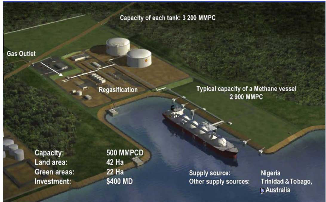
A GBS is a fixed concrete structure laying on the sea floor. The structure is installed with the LNG storage tanks and regasification equipment. The Adriatic LNG terminal located 9 miles (14 km) offshore near Rovigo, Italy in the northern Adriatic was the world’s first offshore gravity-based structure LNG regasification facility.
It is designed around a large concrete structure in 95 ft of water, which houses two LNG storage tanks, a regasification plant, and facilities for mooring and unloading LNG vessels. The terminal is operated by Qatar Terminal Limited, a subsidiary of Qatar Petroleum, ExxonMobil Italiana Gas, and Edison. The terminal is 47 meters (154 ft) high, 88 meters (289 ft) wide, and 180 meters (590 ft) long.
An FSRU is an LNG ship that can be a custom design or an existing carrier modified to include there gasification facility. They are floating structures, either moored to the seabed via a turret mooring system or tethered to a jetty in a port area. The GBS design is more permanent and takes longer to build, and the capital cost is higher. However, the GBS design can be expanded for higher through put while FSRU is limited by the real estate on the ship.
Onshore LNG terminals
A typical onshore LNG receiving terminal process schematic is shown in Picture 17. Picture 18 also shows the process units and the plant layout of a typical onshore LNG receiving terminal. As can be seen from Picture 17, LNG is unloaded by means of the ship pumps to the unloading arms on the Jetty and then to the storage tank through the unloading lines. It is then pumped to high pressure through various terminal components where it is warmed in a controlled environment. The LNG can be heated by several methods including direct-fired heaters, seawater, heated water, or air. Once regasified, the natural gas is delivered into the distribution pipelines to the different uses or power generation stations.

The process of an LNG receiving terminal is further described in the following.
LNG ship unloading
In most LNG terminals, ship unloading usually takes about 12 hours for a 145 000 m3 LNG carrier with an average unloading rate of 12 000 m3/hr. LNG is typically unloaded into a single tank. There are other activities before and after unloading, such as turning basins, berthing, preparation for unloading, and departure. The total time that the ship stays at port is about 24 hours.
Three LNG unloading arms plus one vapor return arm and a hydraulic arm package are provided on the jetty. One of the LNG arms can also be used as a vapor return arm during an emergency.
A single large unloading line and a small recirculation line are typically installed from the jetty to the storage area. If necessary, the recirculation line can also be used for unloading LNG. During the holding operation, when the ship is not at port, the unloading line is kept cold by circulating LNG from the send out system to the jetty using the small circulation line.
During ship unloading, vapor must be returned to the ship to replenish the unloaded volume from the ship, in order to avoid vacuum conditions. In most installations, vapor return can be accomplished by operating the storage tanks at a higher pressure than the ship, typically at about 8 to 10 KPa higher.
For a long jetty, it may be necessary to use a vapor blower.
After LNG unloading is finished, the unloading arms are purged with nitrogen and the LNG inventory in the unloading arms is recovered, either by draining to a drain drum located in the dock area or pressurized to the storage tanks with nitrogen, prior to disconnect from the ship.
Water hammer. LNG is unloaded at high rates through the ship manifolds, unloading arms, and the unloading line to the tank. Each segment is installed with emergency shutdown (ESD) valves, which are designed for quick closure. These ESD valves are initiated during an emergency and the closure timing of these valves must be configured to avoid potential damages from “water hammer”. A water hammer study is required during the design phase to ensure design integrity of the unloading system during an emergency situation.
Surge pressure, or “water hammer”, is a short-term increase in pressure due to a change in fluid velocity in a pipeline. In a water hammer study, it is assumed that fluid hammer occurs when a valve is suddenly closed and the fluid continues to move away from that valve because of its momentum. A vapor cavity will appear on the downstream side of the valve, and when the fluid runs out of momentum, the vapor cavity will collapse, causing water hammer. Most frequently in a receiving terminal, water hammer is caused by halting the LNG flow by closure of the tank inlet valve. The valve closure sends a pressure wave that can generate a “water hammer” incident.
The water hammer scenarios can be analyzed by transient simulation tools, using software such as AFT Impulse. With this tool, the piping design and ESD valve design can be configured to avoid the potential damage from water hammer.
LNG storage
LNG is stored at atmospheric pressure in double-walled, insulated tanks that are designed for storing the liquids at cryogenic temperatures. The insulation is designed to minimize heat gain and reduce product losses due to boil-off. The boil-off rate from a typical tank is about 0,05 volume % per day.
The tank capacity is typically 160 000 m3, matching the size of an average LNG carrier. Large tank capacity with 200 000 m3 or higher capacity is being built and may become the norm for new terminals in order to match today’s large LNG carriers. Typical LNG tank operating conditions are shown in Table 4.
LNG storage tanks of various designs are employed around the world. Selection of LNG tanks is project specific. They should address site conditions, design criteria, safety, geological considerations, environmental requirements, and applicable design, codes, and regulations. There are two main types of LNG storage tanks:
- in-ground storage tanks;
- and above ground storage tanks.
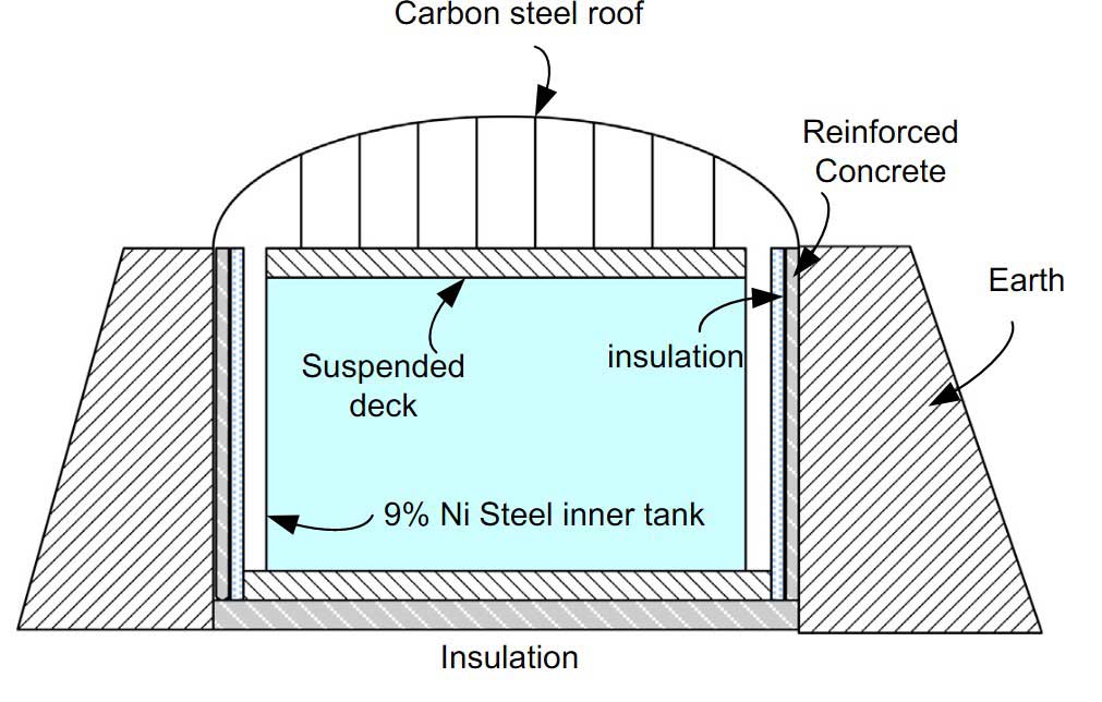
In-ground tank. An in-ground tank consists of a stainless steel membrane, supported by rigid poly-urethane foam insulation (Picture 19). This, in turn, is supported within a reinforced concrete caisson. The roof consists of a dome-shaped carbon steel structure supporting a suspended deck with glass wool insulation.
In-ground tanks are less visible in their surroundings and more secure from an antiterrorist standpoint. There is no risk of spillage with this high-integrity storage design.
It is also more earthquake-proof as the seismic motion is not amplified in the underground tanks compared to the aboveground counterpart. They are common at receiving terminals located at seismically sensitive areas like Japan, South Korea, and Taiwan. With the earth berm, the tanks can be located close to one another, which is an advantage where land and space are limited.
| Table 4. Typical LNG Storage Tank Design and Operating Pressures | |
|---|---|
| Maximum Design Pressure | 30 KPag |
| Vacuum Design Pressure | -1,5 KPag |
| Normal Operating Pressure | 10 KPag |
| Minimum Operating Pressure | 2,5 KPag |
| Maximum Operating Pressure | 25 KPag |
In-ground tanks were developed by Tokyo Gas Engineering (TGE) in the early 1970s, based on earlier designs in the United Kingdom, United States, and Algeria, and subsequently used by other Japanese companies. As of 2005, there were 61 in-ground storage tanks in Japan. The record for the largest LNG tank in the world was first set by an in-ground tank (200 000 m3), although several aboveground tanks have recently been built with a similar capacity.
These tanks are more expensive and take longer to build than aboveground tanks – about 4 to 5 years compared to 3 years for a tank built above ground.
Aboveground tanks. Above ground LNG tanks have two layers of containment. The primary containment is provided by the inner tank, which holds the LNG. Secondary containment is provided either by the use of dykes, berms, and impoundment dams around storage tanks, or by building a second tank around the primary storage tank to contain the LNG, which will protect against failure in the primary tank. All LNG storage tanks are constructed with thermal insulation to minimize heat transfer, reduce boil-off vapors, and protect the carbon steel materials from reaching cryogenic temperatures.
The containment system is designed in compliance with LNG codes and standards, which provide guidelines for material selection and design requirements for LNG storage tanks and other equipment at LNG facilities.
There are basically three tank types used for onshore terminals:
- Single containment tank;
- Double containment tank;
- Full containment tank.
Single containment tank. A single containment tank is composed of a self-supporting inner cylindrical container made of 9 % nickel steel (Picture 20). This inner tank is surrounded by an outer tank made of carbon steel, which holds an insulation material (perlite) in the annular space. The carbon steel outer tank is not capable of containing cryogenic materials; thus the inner tank provides the only containment for the cryogenic liquid.
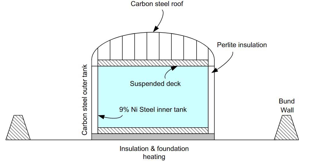
However, single containment tanks are surrounded by a bund wall (constructed of prestressed concrete) or dyke external to the tank, which provides the secondary containment in the event of inner tank failure, although vapor would not be contained. In case of failure, vapor dispersion and flame radiation, if ignited, could result in serious damage to surrounding equipment and structures. The land requirements are greater than for other tanks because of the separation distance between the tank and the bund wall.
This type of tank is the lowest cost option, which has been successfully used in the past. However, because it is more prone to external hazards than other types, insurance premiums are typically higher than the full containment, which penalizes the cost advantages.
Double containment tank. The double containment tank is similar to a single containment tank, with the addition of constructed walls as the secondary containment instead of a containment dyke (Picture 21). Therefore, if the inner tank fails, the secondary container is designed to contain the cryogenic liquid. The outer wall also limits dispersion of the LNG vapor. The outer concrete wall increases the cost of the tank, but less space is required because the containment dyke is no longer necessary.

Full containment tank. A full containment tank is a double containment tank in which the annular gap between the outer and inner tanks is sealed (Picture 22). The majority of LNG storage tanks built in the last 10 years worldwide have been designed as full containment tanks. In this tank, the secondary container is liquid and vapor tight. In case of inner tank failure, the secondary container remains LNG tight. The secondary container wall is generally made of post-stressed concrete and the roof is usually reinforced concrete.
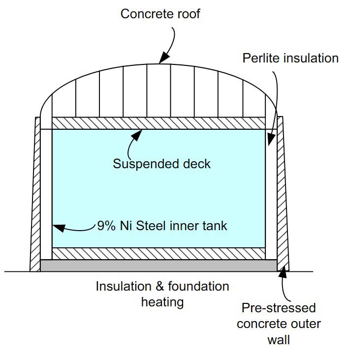
The full containment tank has provisions for top connections only. There are no connections for pipelines or instruments penetrating the sides or bottom of the tank. All connections, such as the top fill line, pump wells, pump discharge, and vapor recovery, are permitted only through the inner tank. Top filling is done via a splash plate device supported from the roof of the tank to obtain good flashing and mixing of the LNG into the tank. This ensures that any superheat associated with the incoming LNG is released by flashing at the tank pressure during filling.
Full containment tanks cost from 10 to 20 % more than single containment tanks (Kulish et al.,2005). However, this type of storage has the advantage of an additional layer of safety against external elements such as fire, blasts, and atmospheric impacts. The full containment tank design is very compact and is currently the acceptable selection for most projects where land availability, location, local regulations and/or security do not permit the use of a single-containment design.
Due to the high costs and long schedule requirements of constructing traditional storage tanks, new LNG storage designs continue to be developed. Two of the advanced solutions, which potentially can reduce construction time and costs, are the All-concrete LNG (ACLNG) tank developed by Arup Energy (Powell and Thomas, 2008) and the concrete/concrete (C/C) LNG tank presented by Statoil Hydro (Skovholt, 2008).
Storage tank operation. The storage tanks are filled with top connections during LNG unloading. Internal piping is configured to permit top and bottom loading. The top loading operation is typically carried out via a spray device/splash plate to promote flashing and mixing of the unloaded LNG with the LNG inventory in the tank. The bottom loading operation is carried using a standpipe that directs the liquid to the bottom of the tank. In general, a lighter LNG is unloaded into the bottom of the storage tank and a heavier LNG is unloaded from the top.
Care must be taken to avoid sub cooling the vapor space in the storage tank. Overcooling may result in a vacuum inside the tank, causing damage to the tank structure. The tank temperature and pressure must be monitored during the tank cooling operation. Tank cool-down is usually carried out before ship unloading to minimize excess vapor boil-off during unloading. The tank must be cooled with the spray and the vapor space temperature kept below -130 °C before LNG can be unloaded into the tank.
LNG tank rollover. Top-filling with LNG of varying densities could result, in exceptional circumstances, in stratification of the LNG inside the tank, which may eventually lead to tank rollover. In another instance, when LNG inventory is stored for a long duration, the top layer of liquid is slowly weathered by vaporization in the form of boil-off gas, and its composition becomes richer and heavier than the lower layer.
As shown in Picture 23, there may be two or more cells of liquid formed with different densities, and when the top layer is heavier than the lower layer, and under a stagnant environment, rollover can occur.
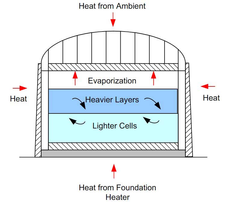
Rollover, the spontaneous mixing of these two layers, will result in the release of a significant amount of vapor in a short time, which may result in overpressure that can lift tank relief valves. More detailed discussions on the rollover phenomenon can be found in Chapter 9 (Section 9.2.5).
Some of the measures to prevent tank rollover are:
- Store liquids of different density in different storage tanks.
- Load storage tanks through nozzles or jets to promote mixing.
- Use filling pipework at an appropriate level in the storage tanks.
- Monitor the LNG shipment cargo density and temperature before unloading.
- Monitor liquid density and temperature profile in the tanks.
- Monitor storage tank boil-off rates.
- Monitor storage tank pressure.
- Transfer contents to other tanks.
- Recirculate the content within the storage tanks using the LP send out pump.