LNG regasification its a process of Liquefied Natural Gas conversion back to natural gas at atmospheric temperature. Article covers basic information about this.
- LNG arms
- LNG pumping
- LP sendout pump
- HP sendout pump
- Boil-off gas recondenser system
- Vaporizers
- Open rack vaporizer
- Shell and tube vaporizers
- Intermediate fluid vaporizers
- Glycol-Water as Heat Transfer Fluid
- Hydrocarbon as Heat Transfer Fluid
- Operating with Low Temperature
- Submerged combustion vaporizer
- Ambient air vaporizer
- Odorization, send-out, and delivery
LNG arms
LNG arms are used for LNG transfer between LNG ship and onshore tanks (i.e., marine vessel unloading). Each arm consists of the riser pipe, the inboard arm, and the outboard arm. The diameter of the arm varies between 16 and 24 in (Picture 1). Typically an LNG swivel joint is installed between each pipe segment, which is used to accommodate the changing positions between the onshore and the ship components. Emergency release systems, quick connect/disconnect coupling (QCDC), and position monitoring systems are provided to ensure safe operation of the arms. A nitrogen purge is also provided for each arm for draining the content prior to disconnection from the ship.
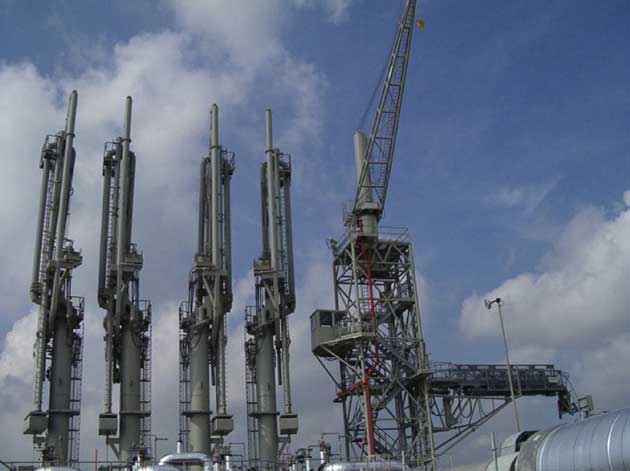
The capacity of a loading arm varies between 4 000 m3/hr and 6 000 m3/hr. Typically, there are two or three liquid loading arms, a vapor return arm, and a common spare arm for liquid/vapor.
LNG pumping
The submerged electric motor pump (SEMP) has been used exclusively in most of the LNG applications. The pump motor is submerged along with the pump, since LNG is a dielectric fluid, electrical cables and the motor can be safely submerged in the liquid. The other safety advantages of a submerged pump over external motor pumps are that there is no penetration required in the tank and mechanical seals are not needed. Several pump vendors are available for this service, such as:
- Ebara;
- Atlas Copco;
- Nikkiso;
- Hitachi;
- and Shinko.
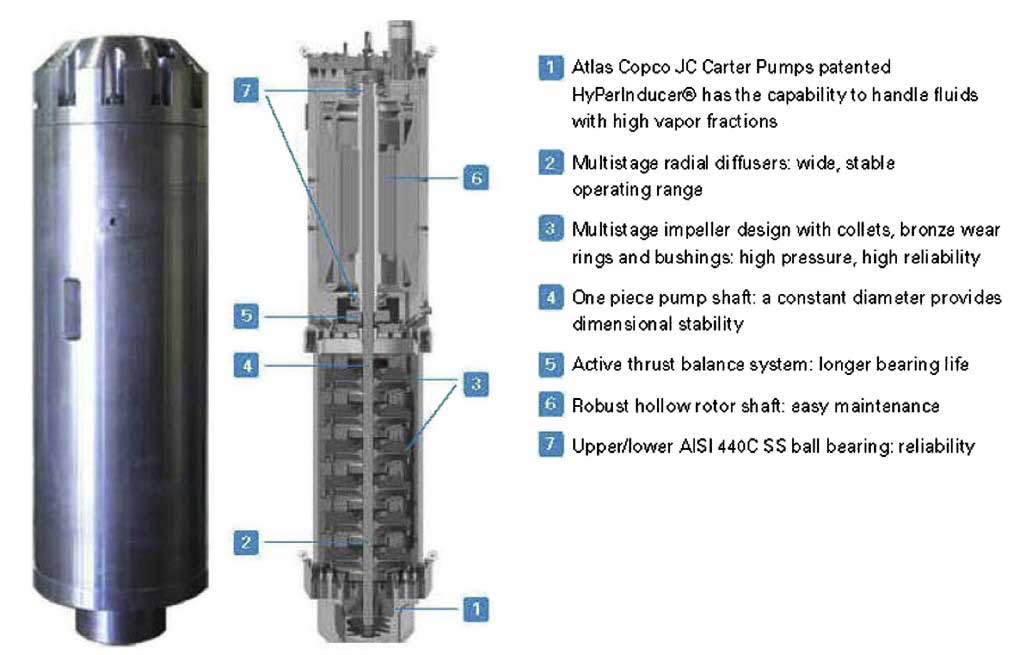
LP sendout pump
The low pressure (LP) sendout pump (Picture 2) is installed in a vertical pumpwell inside the tank. The pumps are retractable and are installed from the top of the LNG storage tanks. The pump weight opens a spring-loaded suction valve, which is used for pump removal and installation. The pump column is purged with nitrogen to ensure safety.
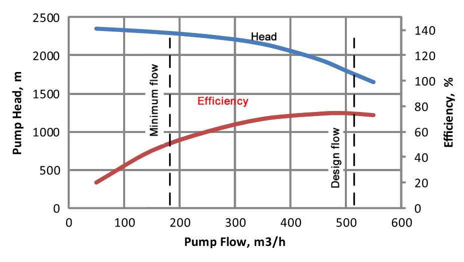
The LP sendout pump typically is designed to discharge at 8 to 10 barg pressure. A typical pump curve is shown in Picture 3. The pump should be operating at close to the design flow for maximum pump efficiency. When the pump flow is operated under turndown, pump efficiency will drop, and the temperature of the discharge liquid will increase, which may cause problems in the BOG recondenser.
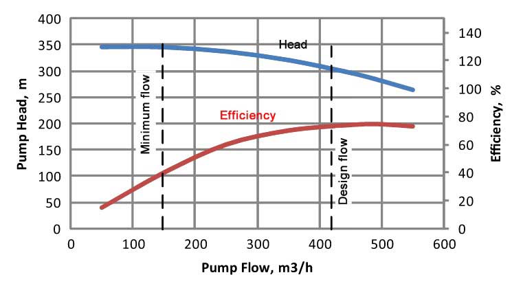
During turndown there may not be sufficient LNG Cold for BOG recondensation, which may result in BOG carryover to the HP sendout pump, causing a pump cavitation problem.
During pump startup, the minimum flow valve will be open to the tank and the pump heat will generate additional boil-off gas that must be recondensed by the BOG recondenser.
In addition to supplying flow to the recondenser and feeding the HP pump, the LP sendout pumpsare also used to circulate cold LNG to the jetty to maintain the cold unloading lines during the holding operation. The pumps can also be used for mixing LNG in the tanks to avoid tank rollover.
HP sendout pump
The high pressure (HP) sendout pumps take suction from the BOG recondenser typically at about 8 barg pressure and increase the pressure to meet the sendout pressure requirements, typically 80 to 120 barg. The HP sendout pumps (Picture 4) are vertical canned type pumps, with submerged motor that drives the closed-coupled, multistage pump.
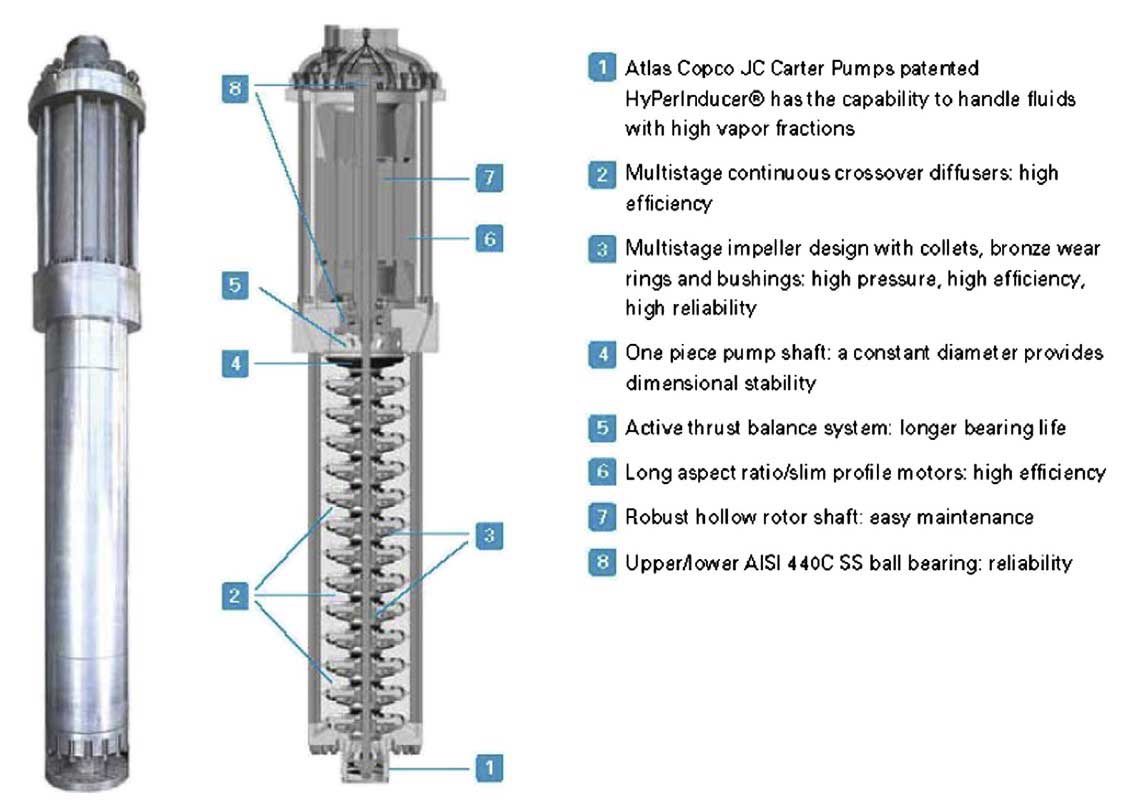
The pump is very compact and is equipped with an inlet inducer to reduce the net positive suction head (NPSH) requirement for operation. A typical pump curve is shown in Picture 5.
Heat generated by the motor is mostly removed by the sensible heat of the inlet LNG. A small portion is vaporized, which must be vented from the pump casing to avoid the pump from being vapor locked. The vent vapor typically is sent to the BOG recondenser. Because of the fact that the BOG condenser and the HP sendout pumps are closely coupled, and that the BOG recondenser liquid is at saturation, the design of the piping system, including elevation of the BOG recondenser, must be carefully analyzed to ensure sufficient NPSH available to operate the pumps. This system is critical in the LNG regasification terminal operation and must be designed for the different pump operations, including:
- startup and shutdown;
- ship unloading, and holding operations.
For a base load terminal, the HP pump is a multistage high-head pump driven by a large motor typically with 1 500 to 2 000 kW rating. Startup and shutdown of this pump requires the minimum flow bypass on the pump discharge to open to prevent the pump from overheating. The pump minimum flow typically is returned to the BOG recondenser, which must be designed with sufficient surge to hold the minimum flow volume while maintaining the vapor recondenser operation.
Boil-off gas recondenser system
The vapor flows from the LNG tanks vary significantly between ship unloading and holding operations. These vapors must be compressed, removed, and condensed in the BOG recondenser to maintain the storage tank at a low pressure.
Vapor flow during ship unloading is contributed to by the heat input from the ship unloading pumps, heat gain in the unloading lines, heat leak to the storage tanks, and volume displaced from the tank by the unloaded LNG. A portion of the vapor is returned to the ship, and the majority is recondensed in the BOG recondenser.
During the holding operation, when the ship is not at port, vapor flow is significantly lower. BOG is generated mainly due to heat leak to the storage tanks, typically 0,05 volume % per day. When the plant operates at high sendout, the BOG flow is further reduced and can become negative such that makeup vapor from the natural gas sendout system may be required.
Typically, the vapor rate varies from 4 to 40 MMscfd between holding and ship unloading operations. These vapor flows are compressed by the BOG compressor and condensed in the BOG recondenser using a slip stream of the cold sendout LNG.
The BOG recondenser serves the following functions:
- Condensing the BOG, maintaining the storage tanks at a low pressure;
- Serving as a mixing drum and suction drum to the HP sendout pump;
- Maintaining a constant suction pressure and providing sufficient NPSH to operate the HP sendout pump.
A typical BOG recondenser system is shown in Picture 6. BOG from the storage tank is first compressed by a BOG compressor to about 8 barg.
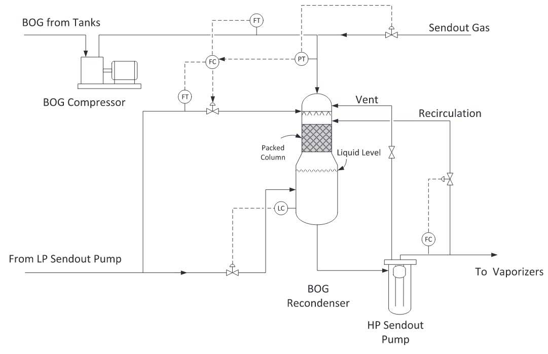
The compressor can be a centrifugal or a reciprocating compressor. Typically two or more reciprocating compressors equipped with automatic unloaders are used to meet the BOG turndown requirements.
The BOG recondenser is designed with a packed section for vapor and liquid contact. Sufficient LNG must be supplied to condense the BOG to produce a saturated liquid. The balance of the sendout flow is mixed with the condensate from the packed column in the lower section of the recondenser.
The process design and control system of the BOG recondenser/HP sendout pump system must ensure a stable flow with sufficient subcooling and NPSH for the HP sendout pump operation.
Some of the key control parameters are:
- Liquid flow rate to the packed column is controlled by a flow ratio controller based on the BOG flow rate. The flow ratio is reset by the pressure controller on the recondenser.
- The main LNG sendout is fed to the lower section of the recondenser under level control on the recondenser. This ensures sufficient liquid is available to the HP sendout pump.
- The liquid level in the recondenser should be kept below the packed section, allowing all the packing to be available for heat transfer.
- The vent from the HP sendout pump is routed to the top of the recondenser, and must be free drained back to the pump suction, to avoid liquid buildup in the vent header.
- HP sendout pump recirculation flow is returned to the recondenser, which must be designed with surge volume.
- Elevation difference between the recondenser and the pump must be sufficient to meet the NPSHR of the HP sendout pump even during turndown operation.
Vaporizers
The optimum choice of an LNG vaporization system is determined by the terminal’s site selection, the environmental conditions, regulatory limitations, and operability considerations. It has to comply with the LNG industry’s requirements for minimizing life cycle costs. The selection should be based on an economic analysis in maximizing the NPV of the project and meeting the emissions requirements.
Today, the base load LNG regasification terminals use two types of proven vaporizers:
- Open Rack Vaporizer (ORV) at about 70 %;
- Submerged Combustion Vaporizer (SCV) at about 20 %.
In addition to these vaporizers, several other types of vaporizers have been used. These include:
- the Ambient Air Vaporizers (AAV);
- the Shell and Tube Exchange Vaporizers (STV);
- and the Intermediate Fluid Vaporizers (IFV).
While the ambient air vaporizers option appears to be desirable in terms of operating costs and environmental considerations, it is also the more expensive option, requiring more real estate, and is more sensitive to ambient condition changes. The vaporizer selection is project- and site-specific and must be evaluated on a case-by-case basis.
Open rack vaporizer
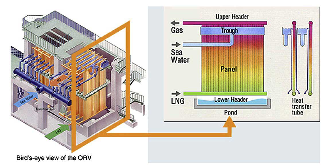
An open rack vaporizer (ORV) is a heat exchanger that utilizes water as the source of heat. The source of water for these units is dependent on the location of the terminal and the quantity of water available. LNG receiving terminals generally are located close to the open sea. Therefore, seawater is the most commonly used source of heat for open rack vaporizers.
These units generally are constructed from finned aluminum alloy tubes, providing the mechanical strength for the cold operating temperature of LNG. Corrosion protection coating is used on surfaces that come into contact with seawater that is sprayed on the outside of the finned tubes.
The mechanical construction of these units is simple. The tubes are arranged in panels, connected through the LNG inlet and the regasified product outlet piping manifolds and hung from a rack (Pictures 7 and 8). This feature provides ease of access for maintenance purposes.

The maintenance of these units is also simple, since there are no moving parts and very little instrumentation is involved. The unit can be started or stopped from a remote control station, without physical intervention of an operator. However, maintenance is more frequent than other types of vaporizers as the tubes should be cleaned regularly.
The operating load on these units can be adjusted by varying the amount of seawater flow to the spraying system and/or the LNG flow through the tubes. Depending on the design of the units, it is possible to isolate sections of the panels and to vary the load on the units.
These units are reliable and have very good safety records. Leakage of gas can be quickly detected and the unit can be safely shut down. There is no danger of explosion, due to the fact that there is no ignition source in the system.
The selection of process design of a seawater heating system must consider the following:
- Is the seawater quality suitable for operating an ORV system?
- Does the seawater contain significant amounts of heavy metal ions? These ions will attack the zinc aluminum alloy coating and will shorten its life.
- Does the seawater contain significant amounts of sand and suspended solids? Excessive sediment will cause jamming of the water trough and the tube panel. A proper seawater intake filtration system must be designed to prevent silts, sands, and sea life from reaching the seawater pump sand exchangers.
- The design must consider the environmental impact of the seawater intake and outfall system, and minimize the destruction of marine life during the construction period and normal plant operation.
- Chlorination of the seawater is necessary to slow down marine growth. However, residual chlorine in the seawater effluent can impact the marine life and the usage must be minimized.
- Seawater discharge temperature must comply with local regulations. The temperature drop of seawater typically is limited to 5 °C in most locations.
- Location of the seawater intake and outfall must be studied to avoid cold seawater recirculation.
- If a site is located in a cold climate region, supplementary heating may be necessary to maintain the outlet gas temperature. Boil-off gas from LNG storage tanks can be used as fuel to these heaters.
- Is a backup vaporization system provided? This may be necessary during partial shutdown of the seawater system or during peaking demand operation.
- Is the LNG regasification facility located close to a waste heat source, such as a power plant? Heat integration using waste heat can reduce LNG regasification duty and would minimize the environmental impact.
Shell and tube vaporizers
Shell and tube vaporizers (STV) can be operated in:
- an open-loop;
- closed-loop;
- or combined mode.
In the open-loop configuration, seawater is pumped from the seawater intake to the STVs to vaporize the LNG. The STV operates in a similar fashion as ORV except that seawater is pumped through the shell and tube exchangers instead (Picture 9).
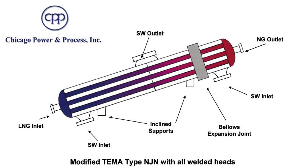
The exchanger shell is constructed of high pressure stainless steel material for the LNG operation and the exchanger tube is constructed of titanium or other suitable materials for seawater operation. The material cost of STV is expensive, but the size is relatively compact, which may be justified in offshore operation.
Intermediate fluid vaporizers
The intermediate fluid vaporizer (IFV) uses an intermediate heat transfer fluid (HTF) in a closed loop to transfer heat from a heat source to the LNG vaporizers. The intermediate fluid can be ethylene glycol or propylene glycol; other low-freezing heat transfer fluids are suitable for the operating temperatures. Heat transfer for LNG vaporization occurs in a shell and tube exchanger.
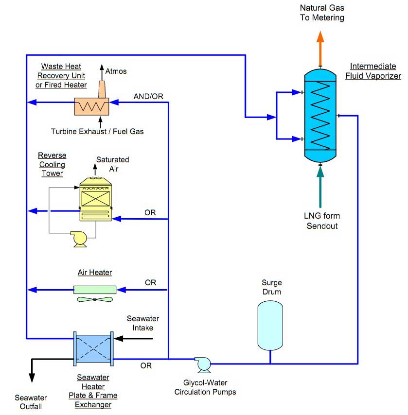
Glycol-Water as Heat Transfer Fluid
The warm glycol-water heat transfer fluid is used to heat up the LNG using the intermediate fluid vaporizers (shell and tube exchanger). The cold glycol-water fluid is pumped by the glycol-water pumps. A glycol surge drum upstream of the glycol-water pumps is used to accommodate the system volume changes during shutdown or startup operation.
There are several options to warm the glycol-water solution, for example:
- waste heat recovery system;
- fired heater;
- air heater;
- plate and frame seawater exchanger;
- and reverse cooling tower.
A general process sketch of this system is shown in Picture 10. These glycol-water intermediate fluid vaporizers have a very compact design due to high heat transfer coefficients.
A selective catalytic reduction system can be fitted into the fired heater to reduce the CO and NOx emissions for environmental requirement compliance.
Today, glycol-water intermediate fluid vaporizers account for only a small portion (around 5 %) of total vaporization capacity in LNG receiving terminals worldwide.
Hydrocarbon as Heat Transfer Fluid
Alternatively, propane or butane can be used as the heat transfer fluid, as shown in Pictures 11 and 12. In this scheme, propane or butane is vaporized on the shell side of a shell and tube exchanger using seawater as the heat source. The vaporized fluid then condenses on the STV that supplies heat to the LNG. The use of a hydrocarbon would avoid the freezing problems encountered with other intermediate fluid.
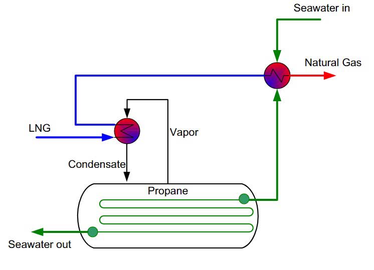
Kobe Steel offers this type of exchanger using propane or butane as the heat transfer fluid in a single shell and tube exchanger called Tri-EX. The design combines the vaporizer and superheater duty in one single shell, split into two sections.

The tubes of the Tri-EX are made of titanium that is required for the seawater service, which makes this exchanger relatively expensive. Kobe Steel has built several of these units since 1987.
Operating with Low Temperature
Seawater One advantage with using propane as the heat transfer fluid in IFV is that when seawater drops during winter to a very low temperature, the exchangers can continue to operate but at a reduced rate, as long as the freezing temperature of seawater (typically at -1.5
°C) has not been reached.
Using the propane as the intermediate fluid as shown in Picture 11, performance of the IFV can be maintained even when the seawater temperature drops to 5 °C. The unit can continue to operate down to 1 °C seawater temperature, but with a much reduced LNG throughput. The reduction in LNG throughput by seawater temperature can be plotted and is almost linear, as shown in Picture 13. The exit gas from the IFV exchanger can be trim heated using the standby fired heater or SCVs.

There are potential fuel savings by operating with a low seawater temperature in very cold climate regions. This application has to be evaluated with the increase in investment of the additional equipment and operation requirement.
Submerged combustion vaporizer
The submerged combustion vaporizer (SCV) system requires approximately 1,5 % of the total vaporized LNG as fuel, which adds a significant operating cost to the terminals. For this reason, SCVs are used only where no other free heat source is available. The SCV scan also be designed to utilize boil-off gas.
In a submerged combustion vaporizer (SCV), LNG flows through a tube coil fabricated from stainless steel that is submerged in a water bath (Pictures 14 and 15). Water in the bath is heated by direct contact with hot effluent gases that exit a submerged gas burner. One SCV can be designed to handle a maximum output in the order of 200 MMSCFD. The unit is compact and does not require large tracts of real estate for installation.
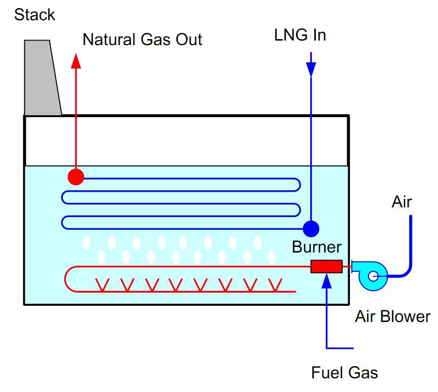
Exhaust gases from the burner are sparged into the water through a distributor located under the heat transfer tubes. This causes rapid circulation of water through the tubes resulting in a very high thermal efficiency (over 98 %) and high heat transfer rate. Agitation from the sparging action also prevents deposits or scale to be buildup on the heat transfer surface of the tubes.

Since the water bath is always maintained at a constant temperature, the system copes well with load fluctuations and can be quickly started up and shut down. The controls for the submerged combustion vaporizers are more complicated when compared to the open rack vaporizers.
The SCV has more pieces of equipment, such as:
- the air blow;
- sparging piping;
- and the burner management system.
These units are reliable and have very good safety records. Gas leaks can be quickly detected and the unit can be safely shut down. There is no danger of explosion, due to the fact that the temperature of the water bath stays below the ignition point of natural gas.
The bath water is acidic as the acid gas content in the exhaust gas is condensed. Caustic is added to the bath water to control the pH value to protect the tubes against corrosion. The excess combustion water must be neutralized before being discharged to the open water system.
To minimize the NOx emissions, low NOx burners can be used to meet the 40 ppm NOx limit. The NOx level can be further reduced by using a selective catalytic reduction (SCR) system in the flue gas stack to meet the 5 ppm specification if more stringent emission requirements are needed, at a significant cost impact.
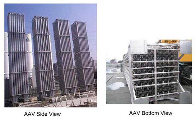
Ambient air vaporizer
An ambient air vaporizer (AAV) extracts heat from the ambient air for heating, hence avoiding the use of seawater or fuel gas. AAVs are considered the more environmentally friendly solution than ORVs and SCVs, and hence are much easier to permit.
The AAV heat exchangers are cost competitive since they can operate on a standalone basis without support of the:
- seawater system;
- intermediate fluid;
- and fuel gas system.
However, the number of vaporizer units is much higher than other options, which would require a larger plot space. In hot humid locations fog generation may be a problem, which should be evaluated for its impact on the surroundings.
Two types of ambient air vaporizers can be considered for the LNG terminals:
- direct air/LNG vaporizers;
- and indirect air vaporizers using an intermediate fluid.
The air exchanger can be operated on a natural draft or a forced draft mode.
A typical AAV design configuration is shown in Pictures 16 and 17. AAV consists of direct contact, long, vertical heat exchange tubes that facilitate downward air draft. This is due to the warmer and less dense air at the top being lighter than the cold denser air at the bottom. Ambient air vaporizers utilize air in a natural or forced draft vertical arrangement. Water condensation and melting ice can be collected and used as a source of service/potable water.
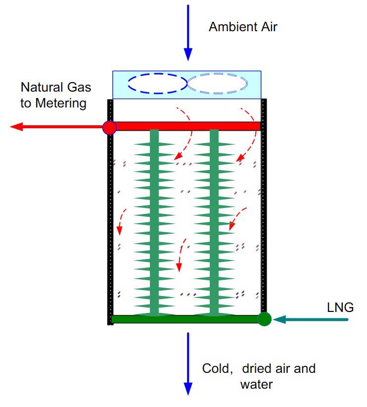
To avoid dense ice buildup on the surface of the heat exchanger tubes, deicing or defrosting with a 4 to 8 hr cycle typically is required. Long operating cycles lead to dense ice on the exchanger tubes, requiring longer defrosting time. Defrosting can be accomplished by natural draft convection or forced draft air fans. The defrosting time with forced fans is only marginally faster, as heat transfer basically is limited by the ice layers, which act as an insulator. However, the high air rate using fans helps to disperse the fog generated by the exchanger and may help to improve visibility.
Fog is generated when the cold air from the vaporizers is in contact with the warm and moist air outside. The extent of fog formation depends on many factors, such as:
- the separation distances among units;
- wind conditions;
- relative humidity;
- and ambient temperatures.
Dense fog may create visibility problems, which may interfere with daily operation.
An ambient air heater is advantageous in hot climate equatorial regions where ambient temperature is high all year round. In the cooler subequatorial areas, where winter temperature is lower, supplementary heating may be required to meet the sales gas temperature.
Odorization, send-out, and delivery
Since natural gas is colorless and odorless, a leak is difficult to detect without appropriate instruments. Therefore, odorization of the regasified natural gas to make the detection of a gas leak easier is required in many regions and countries before it is distributed to consumers (particularly for residential and commercial customers in densely populated areas).
The properties of any odorant used must meet the requirements of local regulations. Odor strength typically is maintained at a level so that gas may be readily detectable at concentrations of one-fifth of the lower explosive limit of gas. This means that the odor is readily detectable at concentrations of gas in air of 0,9 % by volume.
A typical odorant is tetrahydrothiophene (THT) or mercaptan. The odorization station can be in the LNG terminal itself before the send-out of natural gas, or just a few kilometers beyond the terminal on the consumer pipelines. The point at which odorants are added depends on the country. Many terminals that export to a high pressure transmission line do not need to be odorized. Metering, the last step at the terminal, measures the quantity of gas being send out. Natural gas is then delivered by pipeline directly to customers for industrial or residential use.
excellent information
Very detailed and very interesting!