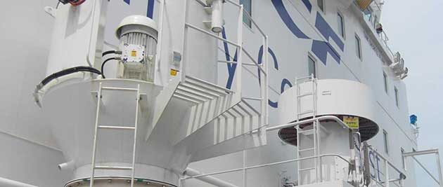
The requirements of “Mechanical Ventilation in the Cargo Area” replace the requirements for ventilation of spaces within the cargo area as required in Rules for Machinery Installations (Part 1, Vol. III) Sec. 15 and SOLAS regulations II-2/4.5.2.6 and II-2/4.5.4.
Spaces required to be entered during normal cargo handling operations
Electric motor rooms, cargo compressor and pump rooms, other enclosed spaces which contain cargo handling equipment and similar spaces in which cargo handling operations are performed shall be fitted with mechanical ventilation systems capable of being controlled from outside such spaces. Provision is to be made to ventilate such spaces prior to entering the compartment and operating the equipment and a warning notice requiring the use of such ventilation is to be placed outside the compartment.
Mechanical ventilation inlets and outlets shall be arranged to ensure sufficient air movement through the space to avoid the accumulation of flammable or toxic vapours and to ensure a safe working environment, but in no case shall the ventilation system have a capacity of less than 30 changes of air per hour based upon the total volume of the space.
As an exception, gas safe cargo control rooms may have 8 changes of air per hour.
Ventilation systems are to be fixed and if of the negative pressure type, permit extraction from either or both upper and lower parts of the spaces dependent on the density of the vapours of the products carried.
In rooms housing electric motors driving cargo compressors or pumps, spaces except machinery spaces containing inert gas generators, cargo control rooms if considered as gas safe spaces and other gas safe spaces within the cargo area, the ventilation has to be of the positive pressure type.
In cargo compressor and pump rooms and in cargo control rooms if considered gas dangerous, the ventilation is to be of the negative pressure type.
Ventilation exhaust ducts from gas dangerous spaces shall discharge upwards in locations at least 10 m in the horizontal direction from ventilation intakes and openings to accommodation, service and control station spaces and other gas safe spaces.
The height of ventilation outlets is not to be less than 3 m above the weather deck or 2 m above the working area or fore and aft gangway if fitted within 3 m of the working area or gangway.

Gas dangerous spaces for the purpose of this paragraph are spaces mentioned above. For other spaces, which are “gas dangerous spaces” only due to their position, relaxations may be granted.
Ventilation intakes are to be so arranged as to minimize the possibility of re-cycling hazardous vapours from any ventilation discharge opening. The ventilation intakes are to be fitted in locations at least 3 m in the horizontal direction from ventilation intakes and openings to accommodation service and machinery spaces and control stations and other spaces outside the cargo area. The height of ventilation intakes is not to be less than 3 m above the weather deck.
Ventilation ducts from gas dangerous spaces are not to be led through accommodation, service and machinery spaces or control stations, except as allowed in “Cargo LNG as fuel”Use of Cargo as Fuel on Gas Tankers.
Electric motors driving fans are to be placed outside the ventilation ducts if the carriage of flammable products is intended. Ventilation fans shall not produce a source of vapour ignition in either the ventilated space or the ventilation system associated with the space. Ventilation fans and fan ducts, in way of fans only, for gas dangerous spaces shall be of non- sparking construction defined as:
- Impellers or housing of non-metallic construction, due regard being paid to the elimination of static electricity;
- Impellers and housing of non-ferrous materials;
- Ferrous impellers and housing including those made of austenitic (stainless) steel with not less than 13 mm design tip clearance.
Any combination of an aluminium or magnesium alloy fixed or rotating component and a ferrous fixed or rotating component, regardless of tip clearance, is considered a sparking hazard and shall not be used in these places.
Spare parts are to be carried for each type of fan on board referred to in this article. Protection screens of not more than 13 mm square mesh are to be fitted in outside openings of ventilation ducts.
Spaces not normally entered
Hold spaces, interbarrier spaces, void spaces, cofferdams, spaces containing cargo piping and other spaces where cargo vapours may accumulate, shall be capable of being ventilated to ensure a safe environment when entry into the spaces is necessary. Where a permanent ventilation system is not provided for such spaces, approved means of portable mechanical ventilation is to be provided. Where necessary owing to the arrangement of spaces, such as hold spaces and inter- barrier spaces, essential ducting for such ventilation shall be permanently installed. Fans or blowers are to be clear of personnel access openings, and are to comply with list above.
The capacity of the ventilation system should normally be 8 air changes per hour. A lower capacity may be accepted for hold spaces surrounding independent tanks after special consideration.
A dry air generation plant, if installed in accordance with “Environmental Control on Liquefied Gas Carriers”Environmental Control, may also be used for ventilation purposes, provided the plant.
