Discover how nitrogen generator system play a crucial role in LNG carrier operations. Explore the uses of N2, generator types, O2 content management, setup procedures, maintenance tips, and safety protocols for efficient and secure vessel operations.
Reference: SIGTTO “LNG Shipping Suggested Competency Standards”, Sections:
1 Have an awareness of their purpose, the different types and their operating principles:
- requirements for and uses of nitrogen.
2 Know and understand nitrogen generator operating principles and parameters, the outlet requirements and limitations:
- dew point;
- temperature requirements;
- buffer tank.
3 Know and understand operational requirements and procedures:
- setting up;
- starting;
- shutdown;
- maintenance.
4 Know and understand bulk liquid nitrogen storage systems:
- loading;
- regasification.
5 Know and understand alarm settings and resulting actions.
Uses of N2
N2 is the most common naturally occurring gas. It represents 78 % of the volume of the atmospheric air, with O2 making up 20,9 % and the balance consisting of other trace gases.
N2 as generated on board cannot support life.
N2 is used for its inert properties in circumstances where the carbon dioxide (CO2) in combustion generated IG would freeze in close proximity to an LNG cargo. Large volumes of N2 for inerting can be taken from ashore if required post-refit.
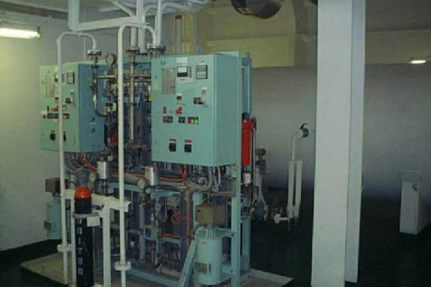
Generally, N2 is created on board ship to:
- prevent the formation of flammable mixtures in the event of a leak;
- allow easier detection of an LNG leak in protected spaces;
- prevent corrosion.
LNG ships produce N2 for the following purposes:
- inerting the interbarrier spaces;
- inerting the cargo tank insulation spaces;
- inerting the hold spaces;
- purging cargo pipelines;
- purging cargo heaters and other cargo machinery;
- purging boil-off gas lines on the deck/engine room;
- sealing glands on HD/LD compressors;
- mast riser fire extinguishing;
- instrumentation.
Types of generator
Nitrogen generators – membrane type
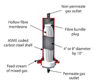
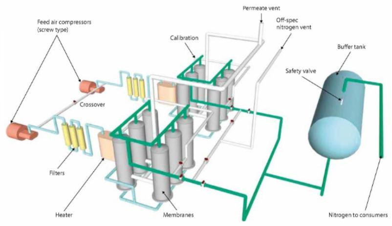
Generally, nitrogen generators on board ships use an air-separation process. This works by passing compressed air across a membrane, which separates the air into two paths:
- one containing the N2;
- the second containing the O2, CO2 and the other trace gases found in the atmosphere.
N2 generator/typical details | |
|---|---|
| Capacity | 150 m3/h @ 97 % N2, 3 % O2 |
| No. on board | 2 |
The capacity of the air-separation membrane nitrogen generators depends on:
- the number of membrane modules;
- air inlet pressure and temperature;
- the required purity of the N2.
Typically, an air-separation membrane nitrogen generator produces a gas of 95-97 % purity.
Adsorption: This process describes accumulation on the surface of a solid.
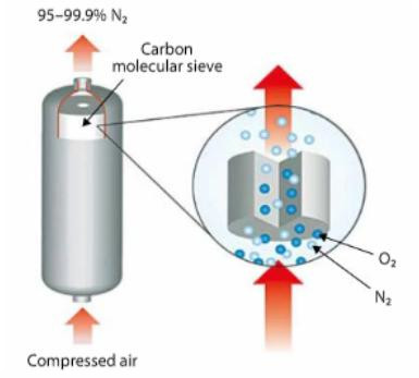
Another common type of nitrogen generator is the PSA type. Its carbon molecular sieve retains O2 in the air, allowing the N2 to pass through.
There are two adsorber beds that are alternatively pressurised then depressurised (for regeneration) in a cyclic process. O2 content as low as 4 ppm can be achieved when using the adsorption type nitrogen generator.
N2 produced from the generator must be dust and oil free and meet the following minimum quality requirements:
- O2 ≤ 3 % volume.
- dew point ≥ minus 65 °C (-65 °C) at atmospheric pressure.
| Physical properties of N2 | |
|---|---|
| Colourless | |
| Odourless | |
| Density close to air | 1,25 kg/m3 |
| Liquid temperature is | minus 196 °C (-196 °C) |
| Liquid SG at boiling point | 1,81 |
| Vapour SG at +15 °C/1 bar abs | 0,97 |
| Gas volume/liquid volume ratio at minus 196 °C (-196 °C) | 695 |
| Flammable limits | none |
Dew point of 100 % pure N2 | below minus 80 °C (-80 °C) |
O2 content
The nitrogen generator will be equipped with an oxygen analyser, connected before the remotely operated 3-way valve that continually monitors the O2 content in the generated N2. If the O2 level rises 1 % above the desired value an alarm must activate. If the O2 level rises further the high-high alarm must operate. Flow must be re-directed to the atmosphere and the discharge line to the buffer tank closed.
Buffer tank
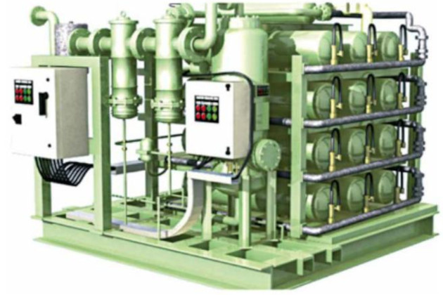
Two nitrogen generators are normally installed in the engine room. The capacity of these units is such that one will be capable of all normal service requirements within a 20 % margin. For periods of high demand, such as the initial cooldown of the Cargo System – Tank Constructioncargo system, this load may be satisfied by having both generators operating in parallel.
A nitrogen generating system should include a buffer tank with sufficient capacity (approx. 40 m3) to ensure that the system need not start up more than once in a two hour period during normal operations at sea.
Start-up and shutdown procedures must always be as per the manufacturer’s recommendations for the equipment.
The nitrogen generating plant must operate automatically and allow remote control and monitoring from the cargo control room.
The N2 generated should be diverted/vented if the O2 content exceeds 3 % by volume.
The two nitrogen generators, which are each typically of 150 m3/h, will be able to produce 300 m3/h of N2 at a delivery pressure of 4-6 bar. The highest demand period will be when topping up the insulation spaces/annular space during cargo loading and cooldown.
Setting up
The control panel is fitted with the following:
- push-buttons for start/stop operation;
- push-button to acknowledge alarms;
- electrical heater temperature control;
- emergency stop push-button.
It also has the following alarms and indicators:
- system status indications;
- continuous N2 delivery pressure;
- continuous O2 content reading;
- dew point analyser.
An oxygen analyser, after the membrane, monitors the oxygen content and, if it is out of range, redirects the flow to the atmosphere.
Typical nitrogen production system (schematic shown below):
Initial starting/shutdown
Start one nitrogen generator to pressurise the buffer tank (in the event of a large demand for N2 the second nitrogen generator will automatically start).
Adjust the setpoint of the N2 supply regulating valves.
The programmed stopping sequence (shutdown) will be initiated by pressing the stop button.
Maintenance
Maintenance is organised as per the established planned maintenance system (PMS), which must cover the following:
- filter changes;
- screw compressor oil changes;
- screw compressor vibration analysis records;
- O2 meter calibration checks;
- humidity meter calibration checks;
- completion of the relevant section in the alarm test register;
- performance of the automatic drain traps;
- membrane performance checks (contamination).
It is recommended that there is a plan for balanced running of the two nitrogen generators. It is found that if they are not run for about 3-4 hours every week, or if they are not operated for a considerable period, it can take several hours of running before the N2 quality is at an acceptable level when they are brought in to service.
A typical mechanism used on older classes of ship was to load liquid N2 (LN) across the manifold into bulk storage while alongside at the discharge port. This facility would normally be set up as part of the construction of the terminal.
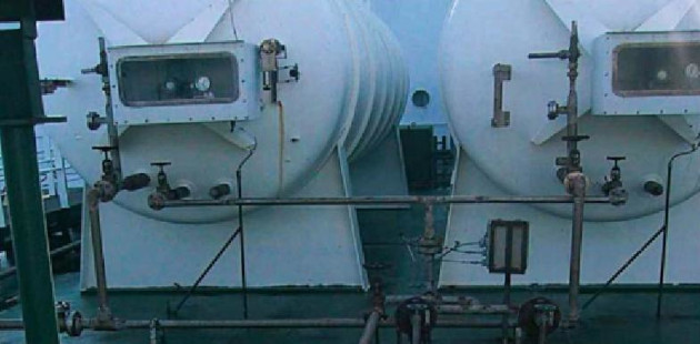
The innovation of N2 generating plants, and the ever increasing requirement for the International trade of Liquefied Natural Gas in maritime industryLNG trade to extend beyond long term liner trade projects and toward spot market trading has brought about the demise of onboard LN bulk storage systems.
Alarms and shutdowns
The following are the usual trip setpoints on an N2 generator:
| Alarm | Trip point |
|---|---|
N2 Generator feed air temperature, high-high | +65 °C |
N2 Generator filter differential press high | 0,6 bar |
N2 Generator air heater temperature high | +120 °C |
N2 Generator O2 content high | 3,5 % |
N2 Generator O2 content high-high | 4,0 % |
N2 buffer tank pressure low | 5,5 Barg |
N2 buffer tank pressure high | 10,0 Barg |
N2 Generator dewpoint level high | minus 60 °C (-60 °C) |
