The design and construction of LNG storage tanks involve meticulous planning, engineering expertise, and adherence to stringent safety standards. These tanks are typically double-walled with a primary containment system made of cryogenic materials such as stainless steel or nickel alloys to withstand extremely low temperatures.
Insulation materials such as perlite or foam are utilized to minimize heat transfer and maintain the LNG in its liquid state. Additionally, safety features such as pressure relief systems and leak detection mechanisms are integrated to ensure the secure storage and handling of LNG.
Reference: SIGTTO “LNG Shipping Suggested Competency Standards”, Sections:
1 Have an awareness of the self-supporting IGC Code Type A Tanks:
- tank material and dimensions;
- insulation materials;
- tank filling limits;
- leak detection.
2 Have an awareness of the self-supporting IGC Code Type B Tanks (Moss Tanks):
- tank material and dimensions;
- insulation materials;
- tank filling limits.
3 Know and understand the Moss type tanks:
- tank construction:
- properties of material and why such.
- material used:
- skirt construction;
- transitional joint construction.
- Insulation systems:
- panel;
- spiral wound;
- annular space;
- purpose;
- bursting disc.
- Hold Space:
- drip tray.
- location of pipework, pump tower and equipment.
4 Have an awareness of the self-supporting IGC Code Type B Prismatic Tanks (SPB):
- design;
- construction and materials used.
5 Have an awareness of the self-supporting IGC Code Type C Tanks:
- tank material and dimensions;
- insulation materials;
- tank filling limits;
- tank anchoring system.
6 Know and understand the Type C Tank:
- tank design – single lobe, bilobe, trilobe;
- tank construction;
- tank insulation;
- tank anchoring system.
7 Have an awareness of the non-self-supporting Membrane Type Tanks:
- tank material and dimensions;
- insulation requirements;
- tank filling limits.
8 Know and understand the Membrane Type Tanks:
- tank design – types of primary and secondary barriers;
- tank construction – different construction methods, primary and secondary barriers and insulation materials;
- tank pressure requirements – distinguish operating requirements of primary and secondary barriers for all membrane cargo containment systems;
- primary and secondary barrier pressure relief arrangements;
- primary and secondary barrier gas detection and gas limits;
- primary and secondary barrier vacuum pump arrangements for maintenance and testing.
9 Have an awareness of the differences between Type A, Type B, Type C and Membrane Type Tanks:
- distinguish operating requirements;
- operational differences between types.
IGC Code and tank types
Gas carriers are divided into two main groups. These are:
- Liquefied petroleum gas (LPG) carriers, which are designed to carry mainly butane, propane, butadiene, propylene and vinyl chloride monomer (VCM) and are able to carry anhydrous ammonia.
- Liquefied natural gas (LNG) carriers, which are designed to carry LNG, which is mostly methane.
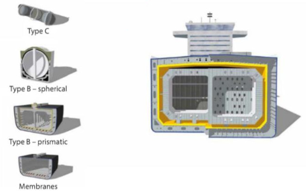
The IGC Code 4.1 defines several types of tanks that carry liquefied gases. These are:
- independent tanks – these are self-supporting tanks that do not form part of the ship’s hull and are not essential to the hull strength. There are three categories of independent tanks:
- Type A – these have a complete secondary barrier.
- Type B – these have a partial secondary barrier.
- Type C – no secondary barrier is required.
- membrane tanks – these are non self-supporting tanks that consist of a thin liquid and gaslight layer (membrane), which are supported through insulation by the adjacent hull structure;
- integral tanks – these are tanks that form a structural part of the hull and are influenced in the same way by the loads that stress the adjacent hull structure. However, these tanks are used for the carriage of LPG and so are not discussed further in this publication;
- semi-membrane tanks – these are non self-supporting tanks in the loaded condition. They consist of a layer, parts of which are supported through insulation by the adjacent hull structure.
The primary tank types currently utilised for carriage of LNG at sea are:
- Moss (spherical) – these are of the Type B category.
- GTT NO96 and Mark III – these are of the membrane type.
Type A
Type A independent tanks are primarily constructed of plane surfaces, with a design vapour pressure less than 0,7 bar.
A complete secondary barrier is fitted. The aluminium tank structure is not integrated to the inner hull of the carrier by means of any metal joints. The inner hull plating and tank are separated by layers of wood and glass fibre panels are used for insulation. The wood usually consists of balsa wood held with plywood and PVC seals.
Hold spaces surrounding the Cargo Containment Systems of LPG and LNGType A tanks are inerted and monitored for oxygen content. The oxygen content is maintained at below 2 % by volume. Portable sampling equipment is considered satisfactory.
Type B
Type B independent tanks are primarily constructed of plane surfaces, with a design vapour pressure of less than 0,7 bar. The tank structure is spherical in shape, with the sphere primarily under the level of the main deck.
During the design process, analysis methods are used to determine stress levels, fatigue life and propagation characteristics.
A partial secondary barrier is fitted. This must be used with a small leak protection system fitted, including the means to detect a leak in the primary barrier and a means to dispose of the liquid.
For further information, see Moss (spherical type) in this section.
Type C
These tanks are primarily constructed based on pressure vessel criteria that is modified to include fracture mechanics and crack propagation criteria. They must have a design vapour pressure of at least 2 bar plus an allowance for stress and physical tank dimensions. Traditionally associated with LPG carriage, they are increasingly used as LNG fuel tanks. They tend to have a smaller volume than Type A and Type B designs.
Type C tanks are usually designed according to three arrangement types. These are:
- single lobe (cylindrical), normally of a size up to approximately 500 m3;
- bilobe, up to a size of approximately 10 000 m3;
- trilobe, up to a size of approximately 13 000 m3.
As single lobe tanks are a poor use of hull volume, the bilobe and trilobe arrangements allow an increased carrying capacity.
Type C tanks do not require a secondary barrier. This is because the higher minimum design pressure is intended to ensure that the dynamic stress on the tank is low and that an initial surface flaw cannot propagate more than half the thickness of the shell of the tank over its lifetime.
They are normally mounted and anchored horizontally, secured on cradle-shaped foundations. They can be fitted on and below deck.
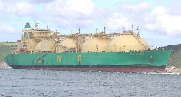
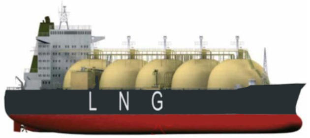
Moss (spherical) Type B
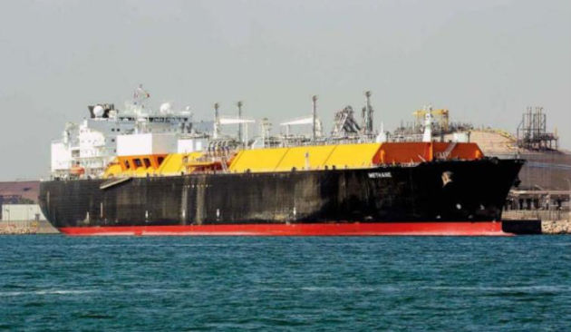
LNG carriers of the Moss system design are classed as using Type B tanks under the IGC Code. They are generally fitted with four or five insulated independent spherical tanks. The Moss containment system was introduced in 1971, with the first ships built in 1973.
Source: wikipedia.org
The containment system must:
- maintain the cargo of LNG at the required cryogenic temperature (minus 161,5 °C (-161,5 °C));
- insulate the cargo from the ship’s structure.
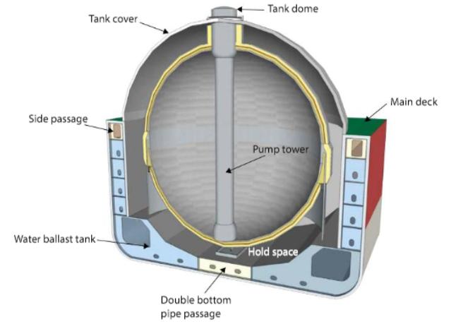
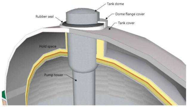
Figure 3 is an example of a spherical Type B tank. Because of its design, a Type B tank requires only a partial secondary barrier comprising of a drip tray and a splash barrier.
As a standard practice, and provided that the space can be made inert if cargo vapour is detected, the hold space is filled with dry air. However, this will be diluted with migrating nitrogen from the annular space while the ship is in service. Before entry, normal tank entry procedures should be followed and spaces must be depressurised and continually refreshed using the dry air plant.
Insulation covers the entire outside of the tank. Above deck, a protective steel cover is fitted to each individual tank. This is known as a weather cover. The rim of the weather cover is welded to the deck to form a watertight seal. In current designs, instead of individual weather covers, a single weather cover is installed over all tanks (this may be referred to as a “pea-pod” or Sayaendo design).
Tank material and dimensions
On a 135 000 m3 Moss system LNGC, the spherical tanks will typically have the following properties:
| Sphere diameter | 40 m |
| Insulation thickness | 250 mm |
| Tank capacity | 34 000 m3 |
| Safety valve setting | 250 mbars |
| Maximum safe working pressure (MWP) | 0,25 bar |
| Maximum test pressure | 2,15 bar |
| Minimum tank pressure | -0,05 bar |
| No. of tanks | 4 |
The cargo tank will be constructed of an annealed aluminium alloy. On older types, there may be a nickel construction.
The sphere will be supported by a cylindrical skirt at the equatorial ring. This fitting allows the sphere to expand and contract freely.
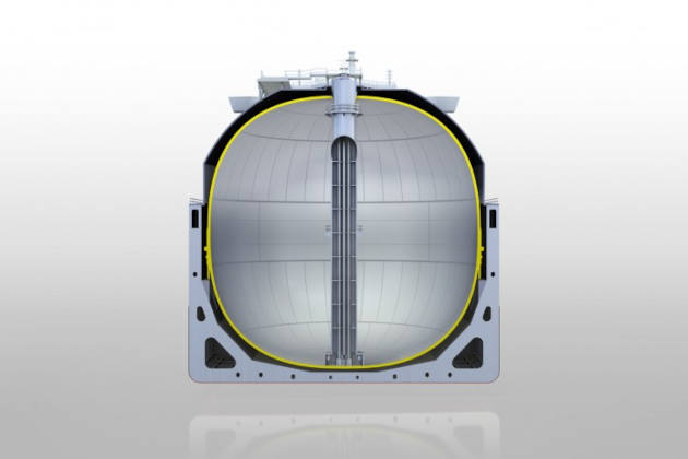
The spherical shape offers good protection against sloshing forces within the tank.
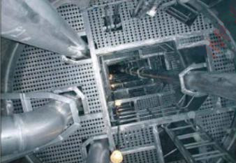
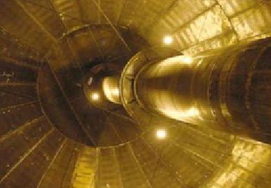
All piping, cabling and pumps will be secured within the “pump” tower at the centre of the tank. Access to the tank is via a series of offset ladders or a spiral staircase within the tower.
The tank will be tested in compliance with the IGC Code and applicable Classification Society and flag State requirements. At initial construction, this will involve filling it to 50 % with fresh water and bringing the air pressure in the vapour space to 1 kg/cm2.
Insulation purposes
The insulation of the Moss system sphere and the structural transitional joint must satisfy two purposes:
- to maintain the cargo temperature at the required cryogenic temperature (minus 161,5 °C (-161,5 °C));
- to ensure that the steel adjacent to the ship’s hull is subjected to temperatures no lower than minus 30 °C (-30 °C). This permits the use of normal grade steel.
Ship’s structural steel exposed to temperatures below minus 30 °C (-30 °C) will crystallise and become brittle.
The liner is made of a thin, non-self-supporting, material.
A liner differs from a membrane in that it is not intended to function as a liquid barrier.
The design vapour pressure will not normally exceed 0,25 bar. However, the Liquefied Natural Gas and Liquefied Petroleum Gas Cargo Containment Systemcargo containment system may be designed for a higher vapour pressure, but this should not exceed 0,7 bar if the internal insulation tanks are supported by the inner hull structure.
Note: A design vapour pressure of more than 0,7 bar may be accepted by an administration provided that the internal insulation tanks are supported by suitable independent tank structures. For example, emergency discharge on the Hyundai class 135 000 m3 Moss system LNGC, will require a vapour pressure of 1,9 bar.
Drainage arrangements for dealing with any non-LNG ingress into the hold or insulation spaces through the adjacent ship structure should be provided.
Inspection of one side of the insulation should be possible unless the integrity of the insulation system can be verified through inspection of the outside of the hold space boundary.
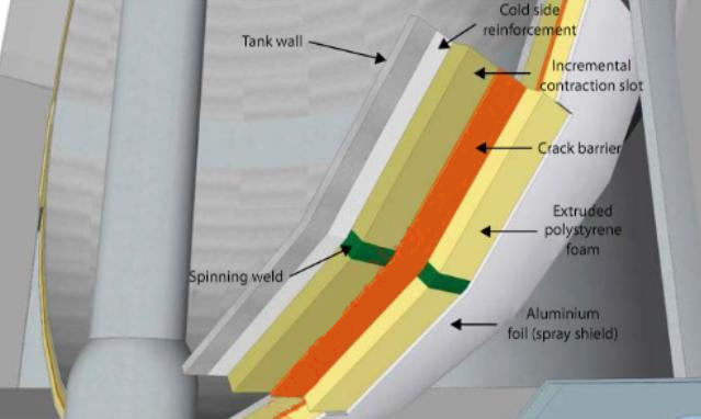
The sphere is covered by polyurethane foam (or expanded polystyrene) insulation blocks of 20-25 cm in thickness, which are sealed by a gas-tight membrane of aluminium foil that drains to an aluminium drip tray at the bottom of the sphere, forming a spray shield. The thickness of the insulation can be adjusted to permit the desired cargo boil-off rate per day. This is normally between 0,1 and 0,15 % of the total cargo volume per day.
Tank filling limits
No cargo tank should be more than 98 % liquid full at the reference temperature, except where permitted by flag States that allows a higher filling limit. This will take into account:
- the shape of the tank;
- arrangements of pressure relief valves;
- accuracy of level and temperature gauging;
- the difference between the loading temperature and the temperature corresponding to the vapour pressure of the cargo at the set pressure relief valves.
Note: 99,5 % filling is commonly permitted by Class and flag States on the Moss system type.
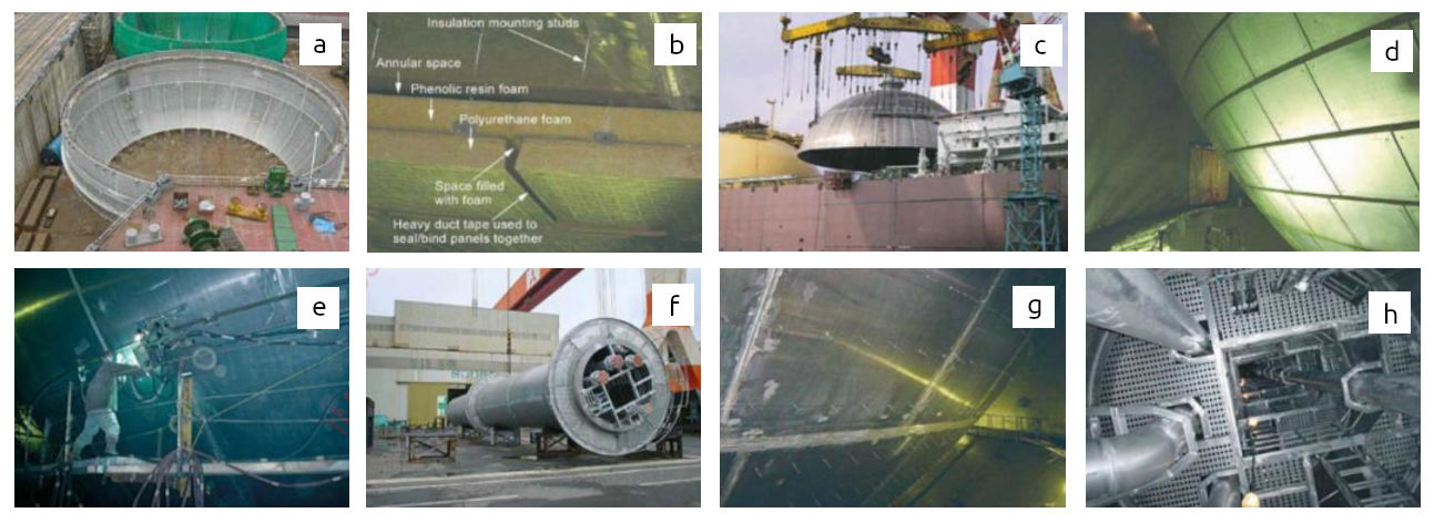
a – equatorial ring section; b – cargo tank insulation showing rods; c – fitting the tank top; d – cargo tank insulation fixing; e – welding the Moss sphere; f – LNG tank, pump tower; g – uninsulated cargo tank showing the insulated mounting rods; h – LNG pump tower
Tank construction
The Moss containment system is based on the principle of “leak before fail”. This means that the tank will leak slowly, allowing a problem to be identified before failure, and not leak/rupture suddenly or totally without prior indication or before remedial action can be taken.
The first two LNG carriers of the Moss type were built in 1973, using 9 % nickel steel for the tank construction. All subsequent ships have been built with aluminium tanks. The cargo tank is a thick, self-supporting, aluminium sphere that is carried by a cylindrical skirt at its equator.
As the tank is a geometric sphere it is unlikely that, under normal operating circumstances, a crack that could lead to a total failure will appear. This recognised inherent strength permits them to have a drip tray only, at the bottom of the sphere, to contain any possible cargo leakage. In the event of a crack appearing, the gas detection system fitted around the equator of the sphere and at the drip tray would detect any LNG leakage.
The drip tray is fitted with a temperature sensor to detect the presence of liquid LNG and an eductor system to facilitate the removal of any such liquid.
Properties of aluminium. Because it has a high tensile strength, good corrosion resistance and a low thermal conductivity value, aluminium is suitable for use in cryogenic applications.
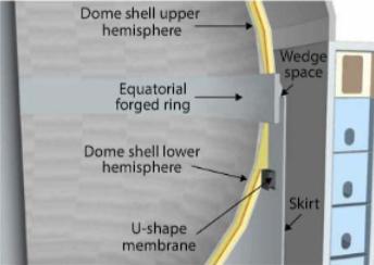
Skirt construction
The Type B tank or Moss sphere is supported by a cylindrical stiffened skirt that is attached to the equator by a unique system that allows the sphere to expand and contract freely while applying minimum stress to the tank shell. The cylindrical skirt is welded as an integral part of the hull structure, with the upper part of the skirt stiffened by horizontal rings and the lower part by vertical corrugated stiffeners. The skirt is designed to absorb the flexing of the hull.
Read also: Materials of construction LNG and LPG tanks
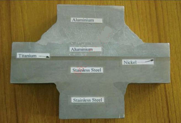
The protrusion at the equator of the tank and the top of the skirt are constructed of aluminium and the bottom of the skirt is low carbon steel. The link between the two parts is composed of a structural transitional joint made of aluminium alloy, titanium nickel and stainless steel. This is bonded together with a thermal break of stainless steel to reduce conduction between the tank and the ship’s structure through the skirt. Typically, the support skirt is insulated using panels of 1,2 m × 1,2 m.
Transitional joint construction. The transitional joint is composed of aluminium alloy, titanium nickel and stainless steel is bonded together using a barrier of stainless steel.
Insulation systems
Two methods are used to fit the insulation to the sphere:
- the spiral generation method, where lengths of expanded polystyrene foam of about 3 min length are woven around the surface by a rotating rig and each length is glued to the previous one. A system of stainless steel straps is woven around the tank and connected to a spring system. This absorbs the weight of the insulation and N2 in the space between the tank and the aluminium gas-tight membrane, which can weigh up to 90 tonnes in the tank’s southern hemisphere;
- the panel method, where individual panels are attached to the tank by studs and an aluminium foil barrier seals the channels between each, leaving sufficient room for the passage of N2 or air and to al low for gas detection.
Both of these methods are designed to limit the natural boil-off.
The Moss system uses a combination of aluminium, steel and stainless steel to improve containment.
In the panel method, the exact composition of the insulation system differs depending at which yard it was constructed, yard of but they are generally formed of several layers of foam, e. g. layer 1 of phenolic resin foam and layer 2 of polyurethane foam.
The insulating structure is reinforced by wire nets and covered with aluminium foil sheet or fibreglass to prevent any ingress of moisture into the insulation when the temperature of the tank is reduced. The insulation also doubles as a “spray shield”.
A spiral wound insulation system is used only on the spherical tank surface. It uses expanded polystyrene foam, provided in rectangular lengths of about 3 m long and 20 cm wide, that are commonly referred to as “logs”. The logs are fitted by a rig that rotates around the outer surface of the tank sphere. As each log is fitted, the next one is glued adjacent to it so that a single spiral of insulation is formed. The logs are butt welded to effectively form a continuous log.
The insulation around the northern hemisphere of the tank rests against the tank surface.
The insulation around the southern hemisphere of the tank is kept in place by an arrangement of stainless steel wire strappings, known as a “cradle”. Each strap has a spring at the end to absorb the changes in load due to shrinkage or movement.
Annular space. The annular space is the space between the cargo tank and the insulation layer.
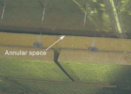
Purpose of annular space
An LNG tank is comprised of an inner tank containment system within an outer tank layer that, in the event of failure, must be capable of containing the cargo for a minimum of 15 days (as per the IGC Code 4.6.2.1).
N2 continuously flows within this space and it is analysed to check for any traces of LNG before it is returned to the hold space. This allows the earliest possible detection of any leakage from the tank which, if the insulation layer was immediately adjacent to the outer tank surface, may otherwise go unnoticed for some time (which the case with prismatic LPG tanks).
Rupture/bursting disc
At the south pole of the annular space is an opening in the insulation that leads to a rupture or bursting disc. This disc is a thermostatic bi-metal plate, made from Invar and a Fe-Ni-Cr stainless alloy, fixed to the flange at one end by adhesive and a screw. When cargo leakage enters the drainage pipe the falling temperature causes a downward deflection of the bi-metal plate, allowing the liquid to pass through the opening and drain into the drip tray below.
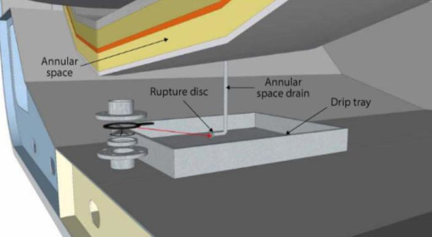
While the rupture disc allows for this drain-off, in normal operation mode it prevents air entering the annular space from the hold space. This also prevents the purge N2 in the annular space from entering the hold space.
Nitrogen supply to annular spaces
There is a constant flow of N2 in the annular space between the insulation and the cargo tanks. This is supplied from the onboard nitrogen plant.
The N2 flows in the annular space around the sphere before returning to the hold space.
The differential pressure between the annular space .and the hold space is monitored. If the differential pressure rises by a difference of ~5 millibar, the N2 in the annular space will vent to atmosphere.
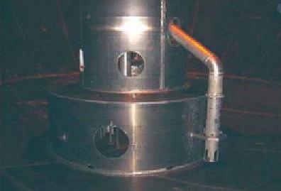
Location of pipework and equipment
All piping, cabling and pumps will be secured within the “pump” tower at the centre of the tank. This allows the following to be fitted:
- a series of offset ladders or a spiral staircase within the tower;
- supporting pipes and cables to the cargo pump;
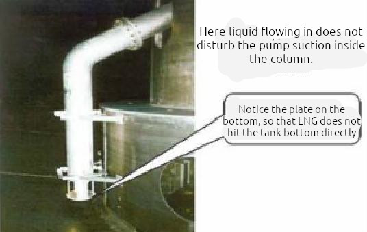
- cargo filling lines;
- spray pump and spray lines;
- custody transfer system;
- temperature probes;
- primary level gauging system;
- backup gauging system;
- liquid level alarms;
- gas sampling lines;
- facilitation of cargo pump removal;
GTT NO96 and Mark III (membrane type)
There are two primary variants on the membrane containment system:
| GTT | NO96 system |
| GTT | Mark I and III system |
Tank material and dimensions
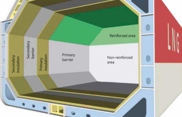
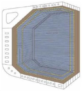
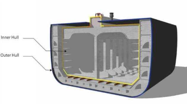
The membrane system is based on a very thin metallic layer (membrane). The inner (or primary) membrane is supported by an inner (or primary) insulation layer. In addition, a secondary barrier and insulation layer is necessary to ensure the integrity of the whole system. The IGC Code 4.6.2.1 states that the secondary barrier must be capable of containing a tank leakage for a period of 15 days.
The N096 system is essentially a tank within a tank. The secondary barrier on the Mark I and Mark III systems consists of a triplex layer.
The membrane containment system is the most popular in use today and is used on the majority of new builds.
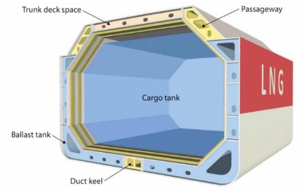
The tank membrane system is adjacent to the ship’s inner hull, which acts as a supporting structure and is able to assist with absorbing any loads such as those created by sloshing, loading and discharging.
Insulation purpose
Insulation on a membrane system has to:
- maintain cargo at the required cryogenic temperature (minus 161,5 °C (-161,5 °C));
- ensure that the steel adjacent to the ship’s hull is subjected to temperatures no lower than minus 30 °C (-30 °C). This permits the use of normal grade steel;
- resist the stresses caused by cargo sloshing;
- ensure that all adjacent spaces are maintained above a minimum of +5 °C.
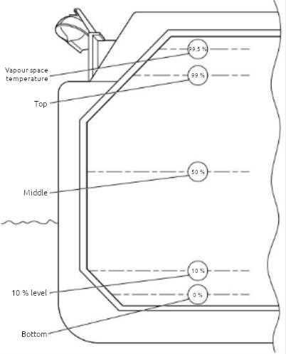
Tank temperature readings
Tank filling limits
According to Chapter 15.3 of the IGC Code, the default value for the filling limit of cargo tanks is 98 % liquid at the reference temperature, though this varies according to ship, tank type and Classification Society.
Usually these values are:
- high (95 %),
- high-high (98,5 %),
- and extremely high (99 %) level alarms.
All filling above 98 % is subject to flag State and Classification Society approval.
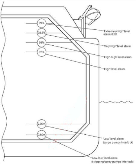
Where a filling limit is authorised above 98 %, the CTMS level alarms will be adjusted accordingly for that ship. For example, where a filling limit is authorised up to 98,5 %, the high-high alarm will be 98,5 % which will trigger the auto-close. The extremely high will be on 99 %, which will trigger the ESD.
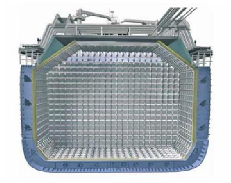
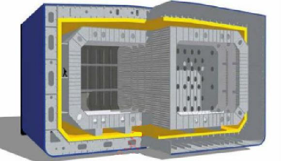
Construction methods and materials used – GTT N096
The primary barrier is an Invar membrane that is 0,7 mm thick and 500 mm wide. (This dimension is for a single “run/seam”).
The insulation for the primary layer is constructed of 200-300 mm thick plywood boxes filled with perlite (a loose granular mineral) – (the perlite is mixed with silicone to make it impervious to water or moisture).
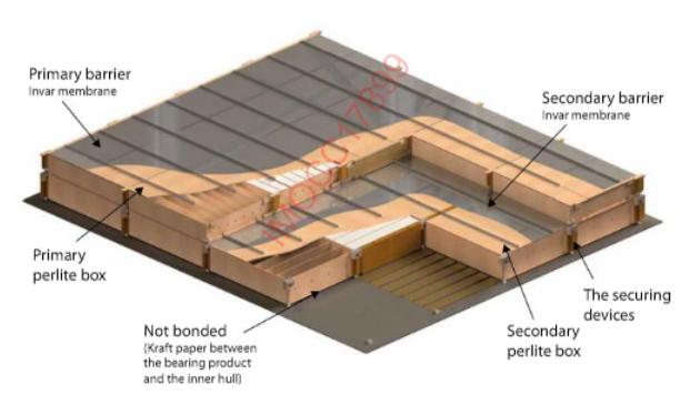
This construction allows them to withstand high impact pressures and absorb the energy from liquid motion when loading, discharging or Dynamic Strength Analysis for Membrane Type LNG Containment System Due to Sloshing Impact Loadcargo sloshing at sea. It will also withstand the head of pressure within the cargo tank. The primary insulation boxes are held on place by collar studs.
The secondary barrier and insulation layer is identical to the primary barrier and offers 100 % back-up. The insulation spaces are inerted withN2.
All piping, cabling and pumps will be secured within the “pump” trellis (tower) at the aft end of the tank. This allows the fitting of the following items:
- access to the tank;
- supporting discharge columns and cables to the cargo pump;
- cargo filling lines;
- spray pump and spray lines;
- custody transfer system;
- temperature probes;
- primary level gauging system;
- back-up gauging system;
- liquid level alarms;
- gas sampling lines.
The trellis is suspended from the tank top and takes the weight of all equipment. The floor of the tank is not weight bearing.
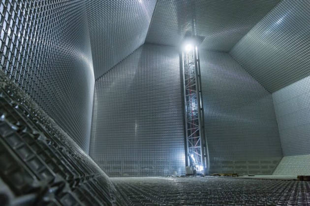
GTT Mark III
The Mark III system was developed to achieve a lower ,cargo boil-off ratio than was achieved by the Mark I system.
The membrane system is based on a thin primary metallic barrier of cross corrugated stainless steel.

The inner (or primary) membrane is supported by an inner (or primary) insulation layer. There is a secondary barrier and insulation layer to ensure the integrity of the whole system.
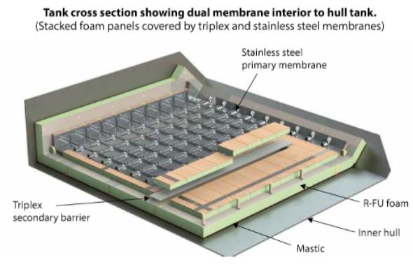
The primary barrier is constructed of stainless steel and is 1,2 mm thick. Its corrugated design allows for expansion and contraction.

The insulation layers are constructed of reinforced cellular foam. In between the insulation layers, a cloth of fibreglass/aluminium laminate acts as the secondary barrier (i. e. triplex layer).
| Comparison of Features of Current Membrane Containment Systems | ||
|---|---|---|
| GTT NO96 | GTT Mark III | |
| Primary membrane | 0,7 mm Invar | T 1,2 mm Corrugated stainless steel |
| Secondary membrane | 0,7 mm Invar | 0,6 mm Triplex |
| Insulation material | Plywood/perlite | Reinforced polyurethane foam |
| Insulation thickness req’d for cargo boil-off of 0,15 % per day | 530 mm | 270 mm |
| Containment system weight | 138 kg/m3 | 73 kg/m3 |
| Welding process | Seam welding | TIG/Plasma |
| Cost | Same as Mark III | Same as NO96 |
Other construction types
The designs described below are not widely utilised in the industry and, to date, only a few LNGCs have been constructed utilising these designs.
IHI SPB (Type B) design
Ishikawajima Harima Heavy Industries (IHI) self-supporting, prismatic type design, using the independent Type B tank criteria, is referred to as IHI SPB.
However, while there were 2 ships constructed pre-2000, this type of tank design is now being considered for new builds again. Because of the tank’s design it requires only a partial secondary barrier.
As standard practice, the hold space is filled with dry air, provided that the space can be made inert if cargo vapour is detected. The advantage of the self-supporting prismatic type of tank is that the entire tank structure is situated beneath the ship’s deck plating. This is similar to a fully refrigerated LPG carrier (which also has a Type B containment system).
The tank is made from aluminium alloy and is 15-35 mm in thickness. This thickness allows the tank to be self-supporting under all loading conditions and this containment type does not experience any sloshing stresses.
The aluminium tank is supported by an insulation system, which consists of a plywood lining that contains an area filled with plastic foam and a 25 mm outer layer that acts as a secondary barrier and can contain any cargo leakage for 15 days. This space is fitted with a gas detection system to test for any failure of the primary barrier.
CS1 design
Combined System Number One (CS1) is designed by GTT and consists of two membranes, the first being 0,7 mm thick Invar. The second barrier is not identical but is a composition aluminium system known as “Triplex”. Insulation is provided by a reinforced polyurethane foam and the insulation volume is smaller than in other GTT designs.
Independent Type C cargo tanks
Type C tanks are normally spherical or cylindrical pressure vessels with design pressures higher than 2 bar. The cylindrical vessels may be vertically or horizontally mounted. This type of containment system is always used for semi-refrigerated gas carriers. In the case of the semi-refrigerated ships, it can also be used for fully refrigerated carriage provided appropriate low temperature steels are used in tank construction. Type C cargo tanks can be found.
Type C tanks are designed and built to conventional pressure vessel codes and, as a result, can be subjected to accurate stress analysis. Design stresses are kept low. No secondary barrier is required by the IGC Code for Type C tanks and the hold space can be filled with either inert gas or dry air.
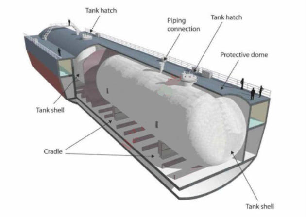
For a semi-refrigerated ship, the cargo tanks and associated equipment are designed for a working pressure of approximately 5 to 7 bar and a vacuum of 0,5 bar. Typically, the tank steels for the semi-refrigerated ships are capable of withstanding carriage temperatures as low as minus 165 °C (-165 °C). These cargo tanks can be found fitted to barges, small scale LNG carriers and floating re-liquefaction units. The tanks can be also provided with Polystyrene slabs as insulation material.
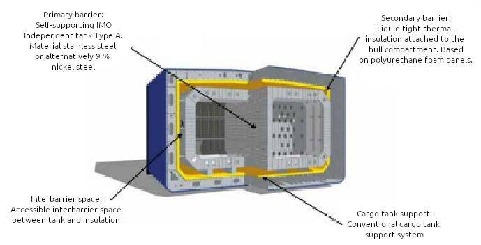
LNT “A-Box” design
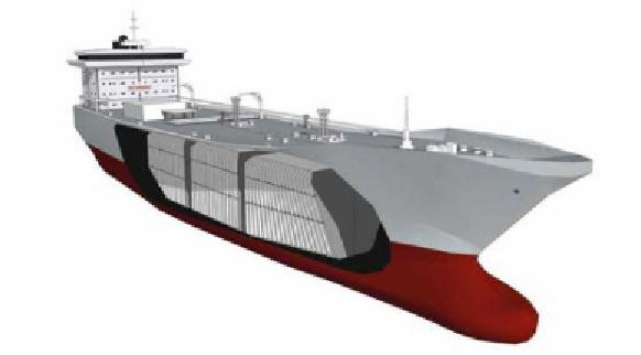
Recently, there has been a new development in containment systems, namely the LNT “A-Box”. Currently only available for ship sizes up to “Med-Max” the “A-Box” concept is a cargo containment system for LNG, and other gases at temperatures below minus 55 °C (-55 °C), and is a complete departure from current containment philosophy and practice.
Development of the system was driven by the recognition that there was a shortage of mid-size LNGCs, that could be constructed incorporating a simple and efficient cargo containment system for this market segment. It is intended to be a simple system that enables more shipyards to build LNGCs. The main features and characteristics claimed for the “A-Box” system are as:
- the system used a new patent-protect configuration that is based on an independent Type A design;
- the tank itself is not insulated, but it is installed in an insulated cargo space;
- in between the tank and the secondary barrier is a cold inter-barrier space that allows direct access for maintenance and inspections.
Operational differences between types
A key operational concern is “sloshing” in LNG cargo tanks. Sloshing in partially filled tanks is a major design issue for membrane tanks in particular, i. e. NO96 and Mark III.
Following research, testing and improvements in tank design, the sloshing criteria changed slightly and so the limits and barred range have been adjusted on new build membrane LNGCs.
Classification Societies and the manufacturers GTT and Marintek carried out a series of model tests to investigate the effects of sloshing in partially filled prismatic LNG tanks. As a result of the tests, the following precautions should be taken to avoid damage from sloshing:
- Cargo tank levels: The first precaution is to maintain the level of the tanks within the required limits i. e.:
- lower than a level corresponding to 10 % of the height of the tank, or;
- higher than a level corresponding to normally 70 % of the height of the tank, or;
N.B. The Certificate of Fitness for the Carriage of Liquefied Gases may presently show the lower limits as being 10 % of tank length. However, this is expected to be corrected in a future update to the model Certificate.
- Ship’s movement: The second precaution is to try to limit the ship’s movement, which generates sloshing in the tanks. The amplitude of sloshing depends on the condition of the sea (wave pattern), the trim and the speed of the ship. A minor alteration of course may change the ship motion considerably, particularly at high speed, and this may have a significant effect on sloshing.
The limits will be stated within the ship specific cargo operating manual and may (depending on the age of the certification) be included in the Conditions of Carriage section of the International Certificate of Fitness for the Carriage of Liquefied Gases in Bulk.
Taking the commercial and engineering issues into account, a comparison of the containment systems reveals:
- some older membrane ships have been known to suffer from gas concentrations occurring in the primary or interbarrier space because of primary membrane porosity. While this is not considered a safety hazard because the space is continually purged with N2, it can give cause for concern. Moss, with the “leak before failure” principle that utilises a single barrier containment, can state that all ships and Moss tanks that are still in service are without detectable leakage;
- due to the reduced metallic mass of the primary barrier, membrane ships generally have a shorter cooldown time of approximately 12 hours, than Moss ships at approximately 24 hours;
- the Moss system is considered to be more robust than the membrane system, with fewer unscheduled off-hire periods due to issues with the cargo system;
- because of better utilisation of the under-deck volume, to achieve the same carrying capacity the membrane and SPB systems require a smaller ship than the Moss system. In addition to needing less steel at the construction stage, this also results in reduced air draught. Fuel efficiency, boil-off utilisation and speed through the water are no longer minor considerations, especially on long sea passages that are frequently undertaken in adverse weather conditions;
- from a navigation and ship handling perspective, larger Moss ships have a visibility issue from the wheelhouse when compared to an equivalent sized membrane ship. In addition, their manoeuvrability can be affected by the large windage area presented by the tank spheres;
- moss and SPB ships are able to carry part cargoes while membrane ships have more limitations on filling because of potential damage from sloshing.
Note: Manufacturers and Class Societies currently recommend constraints on filling levels.
- closely allied to the effects of sloshing in membrane tanks is the issue of fatigue stresses in the primary membrane. Contact between the membrane and the continuous, stepless surface of the load bearing insulation is essential at all times, other than when under repair. While loaded, this is largely ensured by the hydrostatic forces exerted by the cargo. However, in the light ship condition, with only minimal heel in the tank, barrier/membrane contact is maintained by tank pressure alone and it is imperative that the operator ensures that the tank pressures do not fall below makers’ specifications for prolonged periods while the ship is underway. Fatigue stresses in the robust Moss spheres are rarely an operational issue;
- due to its flexibility with regard to partly filled tanks, the IHI SPB system offers a solution as an LNG FPSO;
- for both systems, tank entry in refit is closely controlled, with additional special arrangements required for membrane tanks;
- emergency cargo discharge from a Moss tank can be accomplished without the use of an emergency cargo pump. However, a membrane tank does require this facility.
| Insulation Space Nitrogen Pressurisation Data (typical 145 000 m3 LNG carrier) | ||
|---|---|---|
| NO96 | Mark III | |
| Nitrogen generators | 2 × 90 nm3/h | 2 × 90 nm3/h |
| Vacuum pump | 2 × 1 250 m3/h on board | 300 m3/h portable |
| Interbarrier Space (IBS) | 3 938 m3 | 444 m3 |
| Insulation Space (IS) | 5 829 m3 | 640 m3 |
| Total | 9 767 m3 | 1 084 m3 |