This article provides an overview of offshore gas terminals. As the demand for gas increases, a larger proportion of production is located remote from markets or in areas where pipeline transport is either impractical or uneconomic. Infrastructure costs for gas projects can be a barrier to project development.
- Floating Terminals
- Facility Layout
- Engineering design considerations
- Other considerations
- Topsides Production Facilities
- Topsides production facility (LPG specific)
- Topsides production facility (LNG specific)
- Topsides production facility (regas specific)
- Product Storage and Offloading
- Cargo containment system
- Mooring Systems
- Cargo Transfer Systems
- Side by side offloading
- Tandem offloading
- Hoses for ship to ship and offshore transfer systems
- Surge considerations for ship to ship and offshore transfer system
There is also a need to bring the receiving terminal closer to the end customer and these locations sometimes present problems with terminal siting due to existing development of preferable onshore terminal locations. Several solutions have been proposed to address these issues, the common theme being the use of floating terminal concepts.
Floating Terminals
Floating installations may be located either near-shore (ie alongside a jetty) or offshore (ie moored to the sea floor) and may be either temporarily or permanently moored. They can be purpose built or converted from existing gas carriers. For conversions, the extent of modification to an existing unit will vary, depending on the application.
The facility may have topsides gas processing facilities, used to process reservoir or supply gas into products such as LNG, LPG and condensate and storage capability in the vessel hull. Offshore facilities are usually connected to the natural gas reservoir wells via flexible production risers. Reservoir, subsea control, processing, storage and offloading may be operated from the facility.
The case for floating facilities centres on several key factors: technical acceptability, economic attractiveness and, in some cases, flexibility. Flexibility comes in to play with intermittent markets. Depending upon their design and configuration, units may be moved from one demand centre to another while, in the case of some FSRUs, also maintaining the ability to trade as on LNG carrier.
There ore a number of floating installation types, the most common of which are:
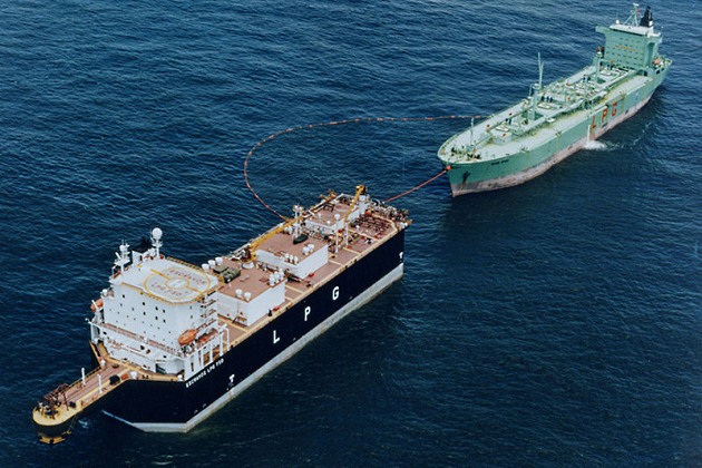
Floating storage and offloading unit (FSO)
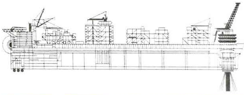
This type of facility consists of floating tankage that receives and stores product for future use, generally for export. Processing of the gas takes place at a separate production facility (see Figure 1) (also known as FSUs).
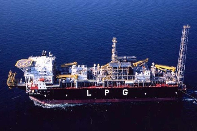
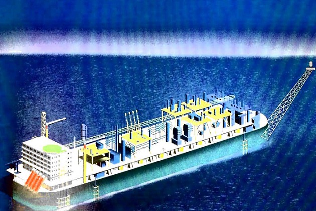
Floating production storage and offloading facility (FPSO)
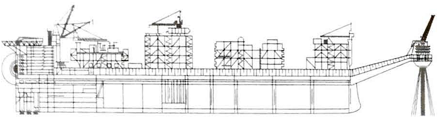
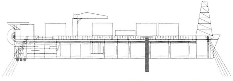
In addition to storage, this type of facility has the capability of some level of processing of the gas supply before it is stored. An example would be an LPG FPSO that receives LPG and processes it into propane and butane for future use (see Figures 2 and 3).
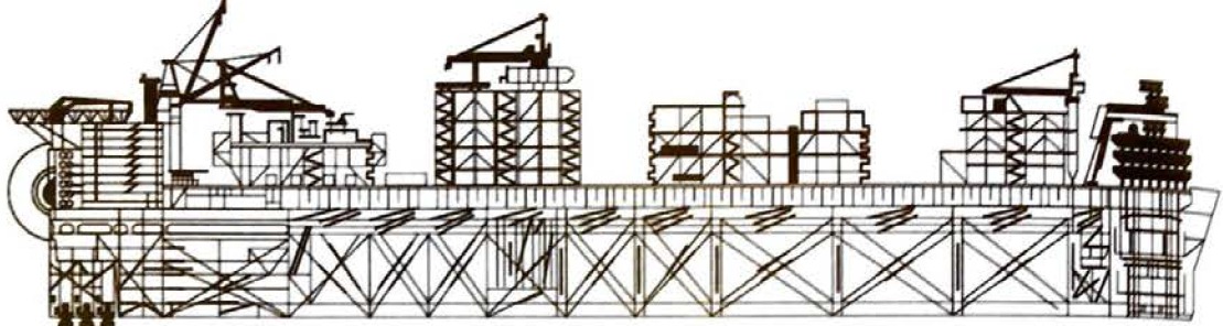
Floating LNG facility (FLNG)
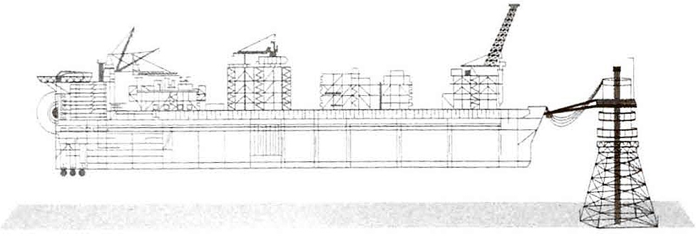
This is an FPSO facility that is exclusively processing natural gas from reservoirs and then storing the resulting products (ie LNG, LPG and condensate) for direct export to ships from the Facility (see Figure 4).
Floating storage and regasification unit (FSRU)
A facility that receives and stores LNG with the purpose of regasifying it for onward distribution to the shore distribution grid. LNG is supplied from traditional gas carriers via STS operation.
Other configurations have been proposed that include floating storage, regasification and power generation, as well as floating liquefaction, storage and offloading (reverse of FSRU).
Motion and acceleration analysis will not be limited to the specific production site as the facility will, typically, need to be transported from the construction site to the eventual production location, so the facility will be designed for the conditions it will be subjected to during transport.
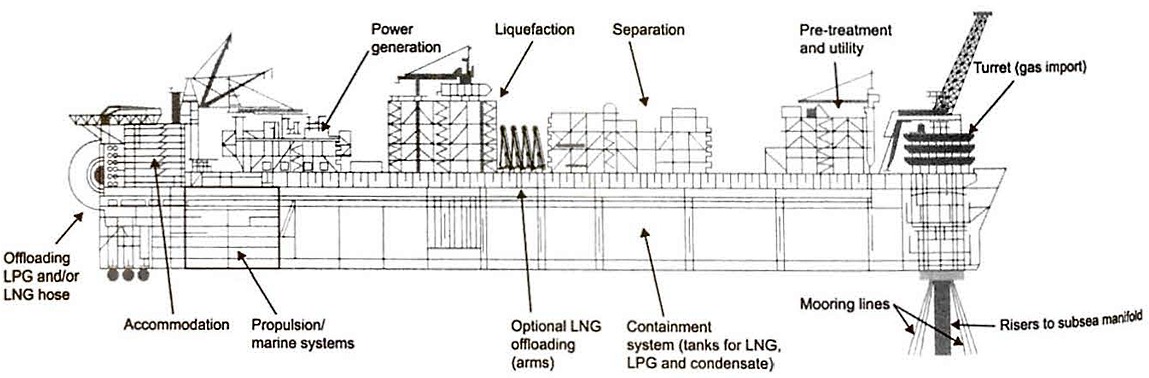
Facility Layout
A facility generally consists of a floating substructure (or hull) that carries some or all of the following:
- Accommodation block;
- topsides process and power modules;
- flare or vent stocks;
- LNG transfer arrangements;
- storage;
- mooring;
- offloading systems;
- lifting appliances;
- risers;
- helideck;
- thrusters.
Structural arrangements of the substructure are largely similar to those on a ship, although the offshore environment creates a different set of challenges, particularly:
- When achieving a compact process plant;
- when “morinising” shore based processing technologies;
- supporting the weight of the topsides equipment while ensuring stability is maintained;
- because of the close proximity of gas processing, storage and living quarters;
- during cargo transfer in exposed, open water areas;
- during simultaneous operations.
The accommodation block (living quarters) is generally located as for away as possible from hydrocarbon storage, high pressure hydrocarbon production systems and facility flare systems.
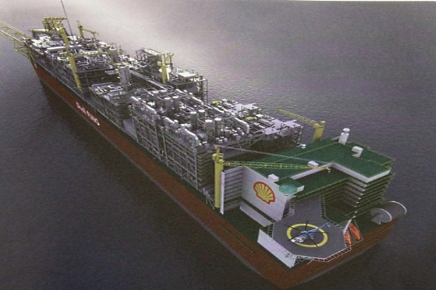
Figure 5 is a representation of the Prelude FLNG facility, built for Shell’s Prelude field off North West Australia.
Engineering design considerations
The design of offshore liquefied gas production facilities builds on the existing technology used in onshore liquefied gas production and in liquefied gas shipping, with some adaptation to make it suitable for offshore application.
The International Association of Oil & Gas Producers (IOCP) publication “Guideline for managing marine risks associated with FPSOs” (Reference 2.48), and the Witherby publication “FPSO Handbook” (Reference 2.49) provide an introduction to the general marine hazards associated with FPSOs.
Issues that are in common with oil FPSO include:
- Separation of areas of high hazard;
- close proximity of processing equipment, product storage, and living quarters;
- marinising and modularising of land based technology;
- simultaneous hazardous operations;
- venting arrangements;
- active and passive fire protection;
- integrated control systems;
- ability to inspect, maintain and repair in-situ.
Additional matters need to be considered for liquefied gas handling:
- The safe handling and storage of hydrocarbons;
- cryogenic and/or high pressure gas processes;
- cargo management and handling of different cargo types;
- partial filling of cargo tanks (which may contribute to sloshing);
- BOG and vapour return management.
The applicable codes and standards will include o mixture of international shipping rules and regulations, Classification Society rules, industry codes, standards, and guidelines, national and international rules and regulations, statutory and Flag State regulations and individual company standards. The applicable codes and standards will differ depending on the operating location of the offshore facility.
This mixture of onshore, offshore and shipping rules and regulations means a gap analysis will often be performed at the beginning of a project to assess the differences between the codes and standards applicable to a project and to determine how potential gaps between them will be dealt with.
Whether a unit is considered as a ship or as an offshore terminal will depend on various aspects of its operation, including whether or not it is capable of being drydocked, and local regulatory considerations
Other considerations
There are additional aspects that may need to be considered during offshore facility design development that are a step-out from technology that is available within the onshore liquefied gas production and the liquefied gas shipping industries.
Extensive structural strength analysis, to assess total and local structural strength, will typically be conducted during facility design. The topsides weight may be considerably greater than the topsides weight of oil FPSO facilities, so the integration of the relatively large topsides weight into a substructure with liquefied gas cargo containment will have been closely considered.
A useful reference is the OCIMF publication “The Safe Transfer of Liquefied Gas in an Offshore Environment (STOLGOE)” (Reference 2.15) which provides guidance on the interrelation between an LPG offshore facility (FSO/FPSO) and conventional gas tankers, primarily in side by side mooring configurations.
Cryogenic safety
As the production facility modules contain a large amount of cryogenic fluids, specific attention has to be given to cryogenic spill protection. The substructure underneath the modules is usually constructed of carbon steel and will, therefore, become brittle if cryogenic fluids are spilled on its surface without protection, potentially severely damaging the structure. For example, shore process plants commonly use cryogenic valves with bottom drains as the ground in a shore plant will be undamaged if exposed to LNG. The situation is very different on board an offshore facility fabricated mostly of mild steel. The cryogenic inventory location and spill potential will be assessed during design and appropriate containment and protection systems will be provided to protect the facility’s carbon steel structures and the overall facility integrity.
Seawater lift
Very large amounts of seawater are lifted from the sea to extract heat from the topsides processes. A lower seawater temperature will increase the overall plant efficiency and, therefore, it may be beneficial to take in seawater at water depths greater than the draught of the facility. This decision depends on the seawater temperature profile at the production site. If the facility is fixed at one location and not transiting, the intake and overboard locations and flows will be carefully evaluated as there is a potential for “recycling” the relatively warmer overboard seawater.
Flare systems
The cargo tank vent systems are generally combined with the production facility flare and vent systems. As the flare and vents on production facilities have a higher throughput than normal ship tank vent systems and are routed to a higher elevation, the backpressure on these systems will commonly be taken into account when evaluating the cargo tanks’ over and under-pressure protection systems. Traditional liquefied gas shipping over-pressure protection systems may need to be adapted to allow tie-in with the topsides pressure protection systems. Vent dispersion and flare radiation studies will usually be performed to determine the appropriate disposal locations.
High pressure system
When compared to an onshore facility, the overall plot space on an offshore facility is significantly reduced so the production facility has to be compacted, which creates space constraints and congestion. This congestion of the production facilities modules, combined with the relatively large hydrocarbon inventory that is processed at relatively high pressures, means that special consideration will be given to blast loads, safety gaps, etc.
As the relatively high pressure topsides production vessels are connected to the substructure product storage tanks via gravity, special consideration will be given to these new high and low pressure interfaces. There is potential for blow-by from the relatively high design pressure sources to the low design pressure cargo tanks. Typically, the pressure interfaces will be assessed during design and pressure protection safety devices will be evaluated against the various blow-by scenarios.
Motion and offshore production
The entire facility is subject to motion, trim and stability and so specific analysis will be conducted to determine the effect of motion on the efficiency of the topsides production systems. All machinery and systems will be designed for the marine environment in which they operate.
Motion and heading analysis
Facility motion and heading analysis is generally performed against a set of metoceon conditions for a specific production site location and against the environmental conditions during transport of the facility from the newbuild yard. The results of the motion and acceleration analysis will be used in many of the facility design aspects, such as the facility structural strength and cargo containment system sloshing analyses.
Heading analyses are performed during design to establish the weathervaning behaviour of the facility, to determine the optimal mean heading under the simultaneous effects of wind, current, sea state and swell and to associate probabilities of occurrence with each heading. The results of the heading analysis will be used in facility heading control requirements, in the offloading operational window analysis and in many other design and operational aspects.
Health, safety, security and environment (HSSE)
Offshore facility major hazards that could lead to personnel injury, damage to the facilities, loss of production and/or pollution of the environment will be subject to hazard identification (HAZID) reviews, HSSE risk assessments and HSSE control and recovery measures through operational procedures and recovery plans.
A few examples of typical offshore specific HSSE risk assessments that may be conducted are:
- Quantitative risk assessment (QRA);
- fire risk analysis;
- cold spill risk analysis;
- computational fluid dynamics (CFD) explosion risk analysis;
- hydrocarbon source inventory;
- evacuation, escape and rescue analysis;
- emergency systems survivability analysis;
- temporary refuge impairment assessment;
- helicopter operations study;
- ship collision study;
- dropped object study;
- CFD exhaust dispersion and helideck study;
- CFD smoke and gas dispersion study;
- wind tunnel testing.
As the outcome of the risk assessments may have a large impact on the overall facility design, they are typically conducted during the front end engineering and design (FEED) phases of a project.
Risk based inspection (RBI)
For a floating offshore asset, which potentially will not drydock throughout its life, the uptime of the entire facility is critical as the cost of downtime and associated loss of production will result in a loss of production revenues. The inspection programme of an offshore asset is, therefore, vital in preventing failures.
The usual inspection and drydocking frequencies for trading ships are reached in accordance with, amongst other things, internationally enforced regulations and Classification Society rules and regulations. These inspection practices do not identify if an inspection activity is excessive and provide no measure of increased assurance on the inspection scope.
The methods, frequency and acceptance criteria used in inspections can affect the likelihood of component failure. To reduce the likelihood of component failure, an RBI approach provides a way to control and monitor the integrity of an asset with a focus on the economic value. Inspection methods and frequencies are continuously adjusted and RBI contains a mechanism to evaluate the consequences and likelihood of component failure from specific degradation mechanisms by developing inspection plans that will effectively reduce the associated risk of failure. The inspection process will be asset specific and updated if the owner undergoes changes in equipment, personnel, operations, structural modifications, etc. and allows focus on areas of greater concern.
Topsides Production Facilities
Topsides production facilities generally include:
- Gas treatment (H2S removal, mercury removal, dehydration, etc.);
- fractionation process (removing ethane, propane and butane);
- power generation and distribution;
- liquefaction (refrigeration and reliquefaction) equipment.
Typically, the equipment is positioned as close to the centreline as possible to accommodate vessel motion/stability.
The topsides production facilities are usually installed as individual modules and supported by the substructure through “module support stools” or “multi-column supports“. On larger facilities it is usual to have side by side production modules supported on the stools at port, starboard and central locations. Generally, all production modules are connected via a central piperack that contains all inter-module pipework and the interface pipework between topsides and the substructure.
During emergency depressurisation and/or other process upset conditions, a flare system is used to safely dispose of and reduce the hydrocarbon inventory of the facility. The location of the flare system will be away (ie downwind) from the facility’s accommodation block and will typically have been evaluated against radiation profiles and other risk parameters.
Topsides production facility (LPG specific)
LPG FPSOs receive mixed LPG streams that are fractionated into propane and butane.
The reliquefaction plant on board an LPG FPSO may be of a different design to simple onboard LPG FSOs or traditional LPG carriers, utilising refrigerants from the propane or butane refrigeration plants to cool the various fractionated products from ambient temperature down to the temperature that allows storage at atmospheric pressure.
LPG facilities generally present fewer storage and transfer challenges than equivalent LNG facilities. However, the depropanizer process plant for LPG production typically involves tall towers, which does present some issues with regard to structural support and motion sensitivity.
Topsides production facility (LNG specific)
The major challenge for FLNG units is that they are required to do more than a conventional onshore liquefaction plant. They are designed to:
- Receive gas;
- process and clean the gas;
- separate out various NGLs;
- store NGLs;
- offload multiple products (and in different ways to different ship types);
- act as an export terminal.
The initial step in the process is when well stream fluids arrive at the FLNG feed gas receiving facilities, where the liquids in the feed gas are separated from the gas. The hydrocarbon liquids are stabilised in the condensate stabilisation unit and may be metered before being sent to the condensate storage tanks. Produced water is separated and treated in produced water treatment facilities before it is discharged overboard to sea or re-injected into the reservoir.
The gas may be routed through metering and a series of treating facilities before the NGLs are extracted. The configuration of the facilities depends on the gas composition and its contaminants, such as H2S, CO2 and mercury. The facilities may include an acid gas removal unit, a dehydration unit and a mercury removal unit.
Once extracted, the NGLs are routed to the fractionation system where condensate, LPGs and the refrigerants used in the liquefaction process are separated out. The LPG may be further split into butane and propane and sent to the LPG storage tanks. The condensate and the refrigerants are routed to their respective storage tanks. The natural gas is then sent to the LNG train(s) for liquefaction.
The LNG is sent from the liquefaction system to storage tanks within the hull structure for offloading at regular intervals. Flash gas from the liquefaction process is combined with the BOG from the LNG storage tanks and compressed to serve as fuel gas supply for the facility power plant and compressor drivers.
Waste heat from the power generation or compressors may also be used as a process heating medium.
Cooling may be carried out using a closed cooling medium circuit. Heat is removed from this circuit by cooling against cold seawater that is lifted/pumped from the sea. These are generally very large volumes of seawater. The temperature of the seawater has a direct effect on the overall FLNG production plant and, therefore, consideration may be given to taking in seawater from deep water depths (see point “Other considerations” above).
Topsides production facility (regas specific)
Regasification vessels (RVs) that transport LNG proceed to a discharge facility, regasify and discharge their cargo, then disconnect and leave to begin a new voyage. They are not normally considered as FSRUs as they are not engaged in continuous regasification operations, nor do they typically receive and regasify LNG simultaneously. RVs are discussed in article “Liquefied Gas Carrier TypesRegasification vesels (RVs)“. The basis for an FSRU design is a standard LNG carrier, and this is the case for conversion of existing LNG carriers as well as for newly constructed units.
There is no single overwhelming factor determining which LNG carrier design makes the best basis for an FSRU, although for conversions, issues such as tank design (ie cargo tank filling limit restrictions), deck space limitations (ie for the required equipment such as heat exchangers and MLAs) and intention to continue using the ship to trade LNG will commonly be considered.
DNV released the “Classification Notes No. 61.3: Regasification Vessels” in June 2008 (second version May 2011) (Reference 2.51). It lists the basic standards for FSRUs and calls for based hazard identification (HAZID) and hazard operability (HAZOP) studies and o full QRA exercise to be performed.
Other societies, such a s Bureau Veritas and the Royal Institution of Naval Architects (RINA), have also released rules and guidance notes for offshore floating terminals.
When moving from an LNG carrier design to an FSRU design, it makes economic sense to use as many of the established LNG carrier’s systems and equipment as possible. In addition to fitting of the regasification unit, which is the most fundamental modification, there are numerous ofher aspects of ship design to consider, including changes to:
- LNG transfer system;
- partial filling of the cargo tanks;
- cargo handling equipment;
- venting arrangement;
- high pressure gas export and metering system;
- power and utilities;
- process controls and communications;
- ESD and fire and gas detection systems;
- fendering requirements;
- ship’s mooring arrangement (both for the FSRU and the offtake tanker).
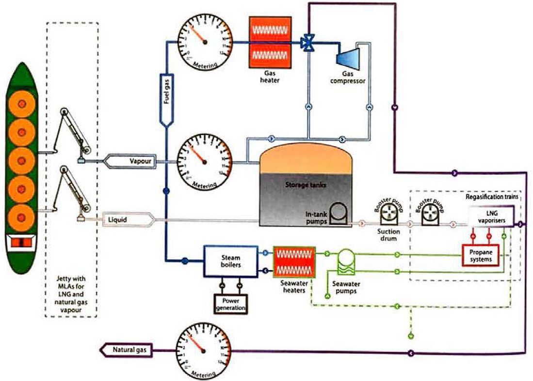
In principle, the process of converting an LNG carrier design into on FSRU may appear as most, if not all, of the technology has been proven elsewhere. An FSRU will require extra pumps, vaporisers, heat exchangers and loading arms/loading hoses. The power will typically need to be upgraded, as will the electrical and control and safety systems. However, unlike RVs (see article “Liquefied Gas Carrier TypesRegasification vesels (RVs)“), built as a series of identical vessels, each FSRU project is unique with adopted solutions to meet an array of project specific technical, operational and commercial demonds. The selected regasification plant may operate in either “closed loop” or “open loop” mode.
Regasification plant – open and closed loop
In closed loop mode, all the energy required for regasification of the LNG is provided by an onboard power supply (normally boilers), with the operation causing minimal impact on the ambient seawater temperature.
In open loop mode, the energy for regasification is taken from seawater, which causes o lowering of temperature between the FSRU regasification plant seawater inlet and outlet.
While on open loop regasification mode will normally be the most economical operation, local environmental requirements will determine whether an open or closed loop design is chosen and, in some cases, the FSRU will be designed with the capability of operating in both open and closed loop mode. This flexible solution appears to be the “normal” design chosen for the steam propelled RVs.
In existing closed loop designs the required heating capacity for the regasification is provided by boilers, which are normally the main boilers for propulsion on steam powered LNG carriers. In cases where high capacity output is required for closed loop operations, additional boiler capacity may be installed.
The heat transfer for regasification between the LNG and the primary heating media (steam or seawater) may be direct or may incorporate a secondary circuit heating media, such as glycol or propane. An open loop seawater system may be shut off from the sea and turned into a closed loop system by heating the resulting “secondary” seawater circuit with steam.
The regasification units are located above deck forward of the foremost cargo tank or, alternatively, above deck within the cargo area. Smaller production pumps (additional to the standard cargo pumps) have to be installed in the cargo tanks to supply LNG to the regasification units. Multiple stage LNG booster pumps lift the LNG pressure to the shore pipeline pressure. The booster pumps and the LNG vaporisers are of designs that are already well proven and in use within the LNG industry (see article “Cargo equipment for gas carriers carrying LNG/LPGCargo Vaporisers“).
Recondenser
Depending on the expected volumes of excess BOG to control, it may be economical to install a BOG recondenser in which the BOG is compressed (to typically 5 to 10 bar), and recondensed by being brought into contact with subcooled LNG in a direct contact heat exchanger. The LNG is subcooled as it is introduced to the recondenser at higher pressure than the LNG storage tanks, which are slightly above atmospheric pressure. The resultant LNG is then led from the recondenser to the vaporisers for send out to the shore system.
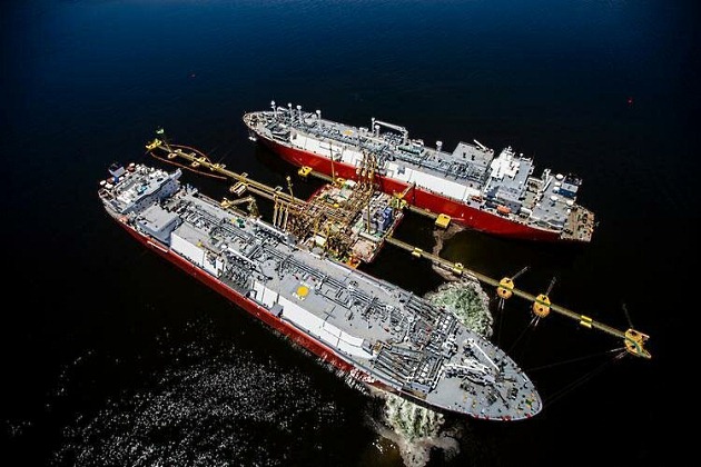
LNG transfer system
The LNG is supplied to on FSRU by a visiting LNG carrier. The transfer of LNG may be via a jetty or may be direct, with the LNG carrier moored at the side of the FSRU.
Side by side transfer is on economical alternative when the FSRU is moored to a jetty structure. If this is to be carried out, the moorings of the FSRU and jetty will typically be confirmed as able to withstand the additional forces generated. Transfer of LNG may be via MLAs (fitted on the FSRU) or hoses. MLAs are preferred, particularly when the operation demands frequent LNG transfers and when the FSRU is not intended to be traded.
Cargo handling equipment
Cargo systems will be modified for simultaneous loading of LNG and the production of regasified natural gas. Alternatives include flaring or using a large HP compressor to send the resulting BOG into the shore pipeline.
Gas export and metering system
Export gas metering may be installed onboard the FSRU or onshore. Local fiscal authorities will have requirements that may result in a need for accurate metering in the fuel supply to both the gas and liquid fuel boilers.
Power and utilities
There is an increased demand for electric power on FSRUs based on steam propulsion plants, and one or more turbine generators will typically have to be added. LNG carrier designs based on gas engines and electrical propulsion will normally have sufficient generator capacity when serving as the basis for FSRU designs.
For process controls, communications, ESD and fire and gas detection systems, there will be an interface between shore systems and systems on the LNG carrier.
Product Storage and Offloading
On a floating terminal, the containment system design is usually determined by the product to be stored.
The produced liquid products are stored within the cargo area and segregated through use of integrated storage tanks. Containment systems are similar, or the same as, those used on trading LNG carriers.
The substructure may also be used to store large quantities of production related fluids, such as methanol and monoethylene glycol (MEG), which are used as inhibitors to prevent hydrate formation in subsea production flow lines. Produced fluids, such as production water, may be buffer stored within the substructure for further treatment before disposal overboard or re-injection back into a reservoir. If applicable, and depending on the type of installed liquefaction process, products such as ethane and propane may be stored for use in the liquefaction refrigerant systems.
Machinery spaces may also contain the facility’s utility systems, such as power generation, seawater lift cooling system, hotel utilities, firewater pumping systems, compressed air systems and nitrogen generation systems.
Cargo containment system
On the offshore facility
On an offshore facility, the liquid level in the tank containment system continuously changes as the facility is subjected to varying environmental conditions.
The motion can cause sloshing, which creates pressure loads on the structure, cargo tank insulation, support structure, pump tower and supports.
Prior to construction any product storage tank, regardless of type, will be assessed for liquid motion sloshing pressures to ensure that the tank design criteria are not exceeded. A basic principle is that, while on station, any product tank requires unrestricted filling levels.
On the offtake tanker
The offtake tanker containment system will also have been assessed for sloshing induced loads. These limitations will, in turn, set the sloshing pressure weather window limitations for offshore cargo transfers from the facility to the offtake tanker. They will also provide insight into the critical filling levels and provide requirements on cargo consolidation should the offtake tanker have to leave the terminal before it is fully loaded. It may be prudent to take into account the coupling effect between the facility and the offtake tanker as it is feasible for facility heave to induce offtake tanker roll.
Mooring Systems
The facility may be moored to the ocean floor, to a conventional berth, to a sea island or, in the case of an RVFSRUs.
A disconnectable mooring system with self propulsion potentially allows a facility to be moved to avoid threats such as extreme weather, if this is deemed the safer option. The choice of mooring system depends on the environmental conditions, site specific conditions, soil mechanics and any potential threats such as hurricanes, typhoons and ice. The most commonly used mooring systems for offshore facilities are:
- Internal turret mooring system;
- external turret mooring system;
- spread mooring system;
- tower mooring system.
Internal turret mooring system
This is typically located at the forward end of a floating production facility and consists of a large roller bearing located within a moon pool. The rotating outer part of the bearing is connected to the ship structure, while the inner part of the bearing is connected to the fixed part of the turret that is connected to the seabed using mooring chains or wires.
This allows the facility to weathervane and rotate around the fixed part of the mooring system. The subsea riser systems are routed through the turret fixed port to a “swivel stack” that transfers the riser contents to the rotating offshore facility. Internal turret mooring can be used in harsh environments and is suitable for deep water applications.
External turret mooring system
This consists of a structure, that is extended at the bow of the floating production facility, that provides the supporting structure for the turret. The turret consists of a rotating and fixed part that connects the facility to the seabed. External turret mooring systems can be applied in a wide range of environments, but have a few limitations (mooring loads, water depth, etc.) over internal turret mooring systems.
The subsea riser systems are routed through the turret fixed part to a swivel stack that transfers the riser contents to the rotating offshore facility. The external turret allows the facility to weathervane a round the fixed part of the turret system.
Spread mooring systems
These generally consist of four groups of anchor chains, located at the forward and aft end of the facility. Two anchor groups would normally be located at the forward end, on the port and starboard sides, with another two anchor groups located on the aft end, again on the port and starboard sides.
Use of a spread mooring system depends on the site’s prevailing metocean conditions as the facility is held in a constant heading and cannot weathervane, potentially exposing it to bad weather from an unfavourable direction. The production risers would normally be supported on the side(s) of a spread moored facility.
Tower mooring systems
These are more applicable to shallow water. The system consists of a tower that permanently sits on the seabed, with a turntable that provides pitch and roll joints to allow the facility to move and weathervane around the tower.
Reservoir gas is transported across production swivels located on the turntable and via jumper hoses to the facility’s production inlet facilities.
Cargo Transfer Systems
Systems to transport liquefied gases offshore can generally be divided into side by side offloading systems and tandem offloading systems. Solutions range from modified traditional MLAs to articulated tandem offloading structures and, potentially, floating cryogenic transfer hoses.
Offshore oil product transfers, with product tankers moored in tandem to an offshore production facility, are commonly carried out at oil production FPSO facilities. The offshore transfer of cargo oil products, including condensate, can be carried out with the offtake tanker either moored side by side, in tandem, or moored to an offloading buoy. If in tandem or from an offloading buoy, product is transferred using floating hoses that are connected to the shuttle tanker’s mid ship manifold or bow loading station.
Side by side offloading
(See: BS EN 1474-3 “Installation and equipment for liquefied natural gas – Design and testing of marine transfer systems – Port 3: Offshore transfer systems” (Reference 2.52)).
When considering a side by side offloading solution for LNG or LPG, factors such as environmental conditions, relative ship sizes, heading control, operating envelopes, elevation differences between the facility and the offtake tankers and the range of product tankers/carriers that will be used may need to be considered. These parameters will be evaluated for every different production site location as they may differ from site to site.
One of the side by side offloading solutions is based on an adapted traditional double counterweight MLA. These MLAs are commonly used for product transfers for onshore terminals to shuttle tankers. Traditional MLAs require a tall base pillar/riser to accommodate swing circle and clearance for the double counterweights that are used. The potential height difference between on FLNG deck and the offtake tanker loading manifold can present a unique challenge which may not allow for the use of a typical MLA design. A fit-for-purpose design, usually comprising a relocation of the main counterweight and a rearrangement of the inboard and outboard arms, may be needed to reach the required operating envelope.
QC/DC, emergency release and targeting systems are very similar to the ones used in onshore LNG MLAs. In an offshore environment, the connection to the visiting LNG carrier may be modified using a targeted spool and a female cone, along with a targeting guide wire. This allows the arm, along with its male cone, to smoothly contact with the manifold, thus avoiding potential equipment damage or personnel injury.
Another solution to the transfer of LNG and LPG in side by side configuration may be to use composite hoses that are connected between the FLNG and shuttle tanker offloading/loading manifolds.
Tandem offloading
For LPG cargo transfers in tandem, floating composite hoses are used at existing facilities.
For LNG transfers, two main configurations are being developed that either make use of cryogenic hose technology or are based on a hard pipe solution. Tandem offloading can be carried out aerially using an articulated offloading structure that supports the cryogenic offloading piping or hoses. Another tandem offloading alternative may be to use a floating hose.
Aerial transfers may be carried out using hard pipe or cryogenic hoses that are hung off an articulated tandem offloading structure that is supported and located on the facility. The shuttle tankers will be connected to the tandem aerial offloading system using bow loading manifolds.
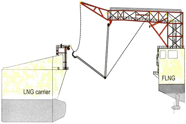
These bow loaded LNG carriers will be purposely built for a specific project as the world LNG carrier fleet is not equipped with bow loading stations.
Hoses for ship to ship and offshore transfer systems
Hoses can be of composite construction or of corrugated stainless steel, but the composite type is generally preferred for STS transfer. Composite hoses generally consist of multiple woven fabric and polymeric film layers, selected based on the product transferred and the required hose mechanical properties, wound between two corrugated stainless steel wires. Hoses used on RVs are normally manufactured from special polypropylene films and fabrics supported by inner and outer wire helixes.
Floating hose transfer solutions for LNG products are currently being developed and verified. They generally consist of an inner cryogenic layer, an outer protective layer made of rubber and intermediate insulation layers. They may also include an integrated leak monitoring system.
Surge considerations for ship to ship and offshore transfer system
STS transfer systems and offshore floating cargo transfer systems are hydraulically very different to conventional cargo transfer loading systems as they do not have high elevation tank pipework to maintain a back pressure on the system during periods of non-pumping. In addition, these types of transfer systems are generally too short for classic surge wave generation. However, STS transfer systems and offshore floating cargo transfer systems may provide more opportunity for vapour pocket formation when the pumps are stopped, as either the MLAs or topsides pipework (on floating offshore terminals) will be the high point in the systems. Even if conditions are not conducive to surge formation, vapour pockets can contribute to unstable flow, noise and vibration. Additionally, some offshore offloading systems use hoses instead of MLAs, which will be assessed at the design stage as hoses have different dynamic properties to rigid pipelines.