Liquefied gas carriers are ships designed specifically for transporting liquefied gases, including liquefied natural gas (LNG) and liquefied petroleum gas (LPG). These carriers are crucial in the global energy trade, facilitating the transportation of natural gas from production sites to consumption centers worldwide.
- Design Standards and Ship Types
- The IGC Code
- Factors affecting gas carrier design
- Gas Carrier Types
- Fully-pressurised ships
- Semi-refrigerated ships
- Ethylene/ethane ships
- LNG carriers
- Regasification vesels (RVs)
- Gas Carrier Layout
- Hazardous Zones
- Hazardous area clossification
- IEC definitions
- Zone determination
- Ventilation
- Survival Capability
- Surveys and Certification
- Certificate of fitness
- Carriage of noxious liquid substances (NLS)
- Materials of Construction and Insulation
- Construction materials
- Tank insulation
- Cargo Containment Systems
- Type A tanks
- Type B tanks
- Type C – tanks (semi refrigerated)
- Type C tanks (fully-pressurised)
- Membrane tanks
- Semi membrane containment system
- Integral tanks
This article provides an overview of gas carrier construction. It starts with an outline of the IGC Code agreed by the International Maritime Organization with later sections discussing the essential elements of design for ship types, cargo containment systems and propulsion systems relating to certain gas carriers.
Design Standards and Ship Types
The IGC Code
While the overall layout of a gas carrier is similar to a tanker, the cargo containment system and its incorporation into the hull is a fundamental difference. This is because of the need to carry the liquid cargo under pressurised or refrigerated conditions or under a combination of pressure and refrigeration.
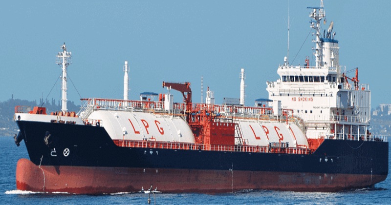
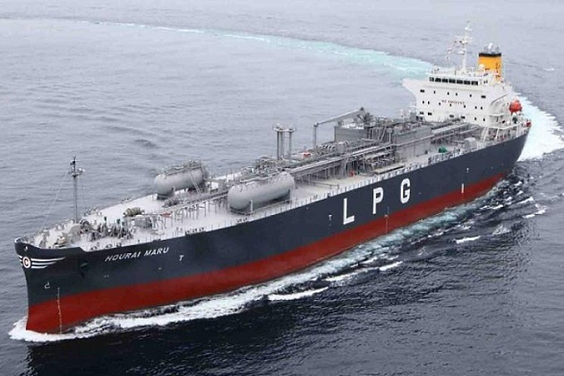
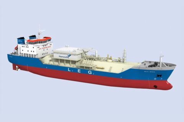
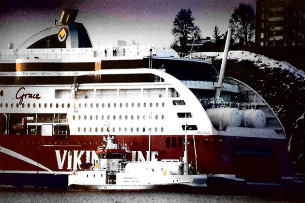
Liquefied petroleum gas (LPG) carriers designed for pressurised cargoes are typically identified by cylindrical tanks that project through the deck. Fully-refrigerated LPG carriers that are designed to carry cargo at atmospheric pressure in prismatic tanks are not easily distinguishable from oil tankers except by their freeboard, which is significantly greater. This greater buoyancy is the result of carrying cargoes of a much lower density than most oils.
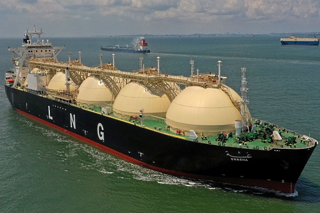
Similarly, a liquefied natural gas (LNG) carrier with either spherical tanks protruding above the main deck or a raised membrane trunk deck can be easily recognised by the distinctive profile and much larger size.
The IGC Code has been amended several times. It is, therefore, important to understand which version of the Code applies to a specific vessel.
The most recent version of the IGC Code, the 2016 Edition, incorporated changes that reflected significant developments in the gas carrier industry, including:
- Procedure for submitting new products for inclusion in the Code.
- protective distances for cargo tanks were increased, using the statistical data relating to collision damage used in the “International Convention for the Prevention of Pollution from Ships (MARPOL)”.
- while specifically excluding LNG floating production storage and offloading facilities (FPSOs) from the scope of the IGC Code, it provides guidance for vessels periodically operating outside the scope of the IGC Code (ie as a floating storage and regasification unit (FSRU)).
- addresses internal turret compartments and piping requirements for regasification vessels (RVs).
- general update on materials, including non-metallic materials.
- reorganised the requirements for cargo pressure/temperature control and introduced requirements for thermal oxidation of vapours.
- added new requirements for sampling connections, cargo filters and high pressure fuel gas piping.
- updated design and operational provisions for pressure relief valves (PRVs).
- changed personnel protection requirements to align with the IMO FSS Code.
- alignment of hazardous area descriptions with IEC standards.
- added new requirements for gas detection and automation systems, including a means of verifying instrumentation on testing at first load.
- clarified permission for filling limits greater than 98 %.
- added a new requirement for a Cargo Operations Manual to be onboard.
- provides detailed requirements for cargo emergency shutdown systems.
Factors affecting gas carrier design
Some of the factors to be taken into consideration and that affect the design of gas carriers include:
- Type and volume of cargo to be carried;
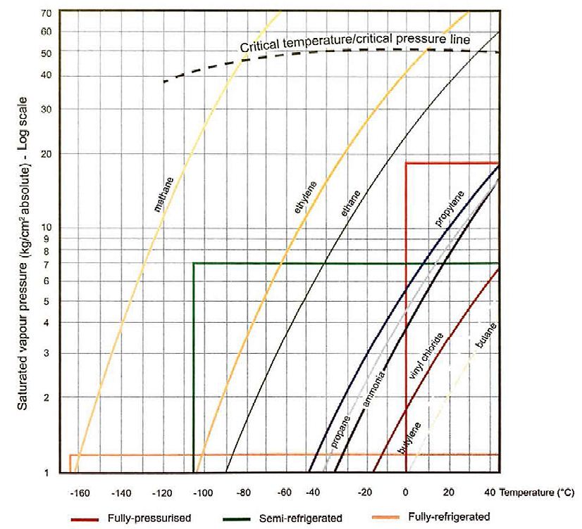
- condition of carriage (fully-pressurised (FP), semi-refrigerated (SR), fully-refrigerated (FR));
- type of trade and cargo handling flexibility required by the ship;
- anticipated terminal activities for loading or discharging the ship;
- commercial considerations, ie size limitations and toll charges for canal transit, Suez or Panama;
- means of handling boil-off gas (BOG) (gas combustion unit (GCU), type of reliquefaction plant);
- propulsion choice, including bunker flexibility for vessels capable of burning BOG as fuel, ie whether to use BOG as fuel or reliquefy BOG and use conventional liquid fuels (marine diesel fuel (MDO), heavy fuel oil (HFO)) when economical.
Section “Cargo Containment Systems” below will provide more information on cargo containment systems and the tank types: Type A, Type B, Type C and membrane.
Gas Carrier Types
Gas carriers can be grouped into six different categories, according to the cargo carried and the carriage condition:
- Fully-pressurised (FP);
- semi-refrigerated (SR);
- fully-refrigerated (FR);
- liquefied ethylene/ethane carriers (LECs);
- LNG carriers;
- regasification vessels (RVs).
Fully-pressurised ships
Fully-pressurised ships are the simplest of all gas carriers. Their containment systems and cargo handling equipment have been established for many years. They carry their cargoes at ambient temperatures above the minimum permitted by their tank design, which is commonly 0 °C but can go down to minus 10 °C (-10 °C) if suitable steels are used. They are fitted with Type C tanks (pressure vessels) (see point “Type C tanks (fully-pressurised)” below) fabricated in carbon, steel and have a typical design pressure of 18 bar. Ships with higher design pressures are in service and a few ships can accept cargoes at pressures of up to 20 bar. No thermal insulation or reliquefaction plant is necessary for these ships and cargo can be discharged using either pumps or compressors.
Because of their design pressure, the cargo tanks are extremely heavy. As a result, fully-pressurised ships tend to be small, with the majority having cargo capacities of about 1 000 to 5 000 m3, although others may be 6 000 to 11 000 m3, and are primarily used to carry LPG and ammonia. Ballast is carried in double bottom and wing tank, if fitted. Because these ships are fitted with Type C containment systems, the IGC Code does not require a secondary barrier and allows for the hold space to be ventilated with air.
These ships carry cargo at ambient conditions and cargo temperatures may be different at each end of the voyage. Allowance should usually be made for this and certain rules apply (see article “Preparation of loading and unloading operations for LNG/LPG carriersCargo tank loading limits“). When equipped with a cargo heater these ships can load from fully-refrigerated storage.
Semi-refrigerated ships
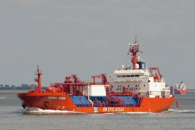
Semi-refrigerated ships, sometames referred to as semi-pressurised/semi-refrigerated ships (SP/SR), are similar to fully-pressurised ships in that they have Type C tanks, which are in this case pressure vessels designer for a maximum working pressure of 5 to 7 bar. Compared to fully-pressurised ships, a reduction in tank thickness is possible due to the reduced pressure, but this requires the expense оf a refrigeration plant, tank insulation and the tanks being constructed from low-temperature steels. This type of gas carrier has evolved as the most flexible means of transporting a wide variety of gases, such as LPG, vinyl chloride monomer (VCM), propylene and butadiene. It is popular among operators of smaller size gas carrier due to its cargo handling flexibility.
It will be interesting: Understanding LNG Tank Atmosphere and Material Properties: Key Principles for Safety and Efficiency
Semi-refrigerated ships use Type C tanks and, therefore, the IGC Code does not require a secondary barrier. Cargo capacities have, for a long time, been predominantly in the 3 000 to 20 000 m3 range but, due to the ethane trade, the size of the ships has increased. Type C carriers о 20 000 m3 and larger are not uncommon. The tanks are usually made from low temperature steels to provide for carriage temperatures of minus 48 °C (-48 °C), a temperature that is suitable for most LPG and chemical gas cargoes. Alternatively, they can be made from special alloyed steels or aluminium to allow for the carriage 104 °C (-104 °C) (see point “Ethylene/ethane ships” below). The ship’s flexible cargo handling system is designed to load from (or discharge to) both pressurised and refrigerated storage facilities.
The tank are supported on wooden chocks and are keyed to the hull by means of anti-roll chocks to allow for expansion and contraction, as well as to prevent tank movement under static and dynamic loads. The tanks are also provided with anti-flotation chocks to avoid lifting in the event of a ballast tank leakage into the hold space.
To improve operational flexibility, cargo heaters and booster pumps are commonly fitted to allow for discharge into pressurised storage facilities.
Fully-refrigerated ships carry their cargoes at approximately atmospheric pressure and are designed to transport large quantities of LPG, ammonia and VCM.
For this class of ship the most widely used arrangement is the independent Type A prismatic freestanding tank capable of a maximum working pressure of 0,7 bar. The tanks are constructed of low-temperature steels to permit carriage temperatures at about minus 48 °C (-48 °C). Fully-refrigerated ships range in size from about 20 000 to 85 000 m3, but there are relatively few fully-refrigerated ships between 55 000 and 70 000 m3. The various ship sizes commonly referred to are:
- VLGC: Very Large Gas Carriers, generally 70 000 to 85 000 m3 capacity;
- LGC: Large Gas Carriers, generally 52 000 to 60 000 m3 capacity;
- MGC: Mid-size Gas Carriers, generally 20 000 to 43 000 m3 capacity.
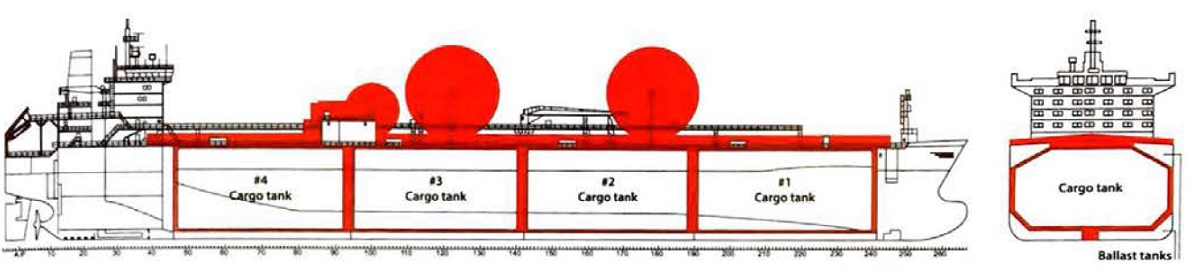
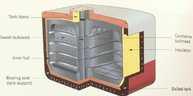
Fully-refrigerated ships below 35 000 m3 usually have three cargo tanks and those above usually have four. Each tank is fitted with transverse wash plates, while a longitudinal bulkhead along the centreline is provided to reduce tree surface to improve ship stability.
The tanks are usually supported on wooden chocks and are keyed to the hull by means of anti-roll chocks to allow for expansion and contraction, as well as to prevent tank movement under static and dynamic loads. The tanks are also provided with anti-flotation chocks to avoid lifting in the event of ballast tank leakage into the hold space. Because of the low temperature carriage conditions, thermal insulation and a reliquefaction plant will be fitted.
To improve a fully-refrigerated ship’s operational flexibility, cargo heaters and booster pumps are often fitted to allow discharge into pressurised storage facilities.
Where Type A tanks are fitted, the IGC Code requires a complete secondary barrier (see point “Type B tanks”), which on LPG carriers may be farmed by the hull structure provided the correct material grades have been utilised for the hull construction. The hold spaces must be inerted when carrying flammable cargoes. Ballast is carried in double bottom tanks or, where fitted, in side and topside (saddle) ballast tanks.
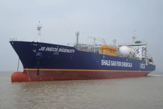
Ethylene/ethane ships
Liquefied ethylene carriers (LECs) are often built for specific trades, but they can also carry LPG or chemical gases. They normally have capacities ranging from 1 000 to 15 000 m3, although larger ships are now common. Ethylene is usually carried in a fully-refrigerated condition at its atmospheric boiling point of minus 104 °C (-104 °C). Type C pressure vessel tanks are generally used and no secondary barrier is required by the IGC Code. Thermal insulation and high capacity reliquefaction is fitted on this type of ship.
Ethane has an atmospheric boiling point of minus 89 °C (-89 °C) and has historically been transported in small LEC vessels with Type C containment systems. As the ethane transport market grows, the physical size limitations of Type C cargo tanks will mean that larger vessels of Type A or Type B containment system design will be required.
Ballast is carried in the double bottom and wing ballast tanks. A complete double hull (double bottom plus side tanks) is required for all cargoes carried below minus 55 °C (-55 °C), when a secondary barrier, partial or complete, is required by the IGC Code for the cargo containment system design.
One important note: LNG cargo tank designs may be suitable for the carriage of liquefied ethane or ethylene, provided the design takes into account the higher densities of ethane and ethylene.
| Cargo | Density (t/m3) | Ratio Relative to Density of LNG |
|---|---|---|
| LNG | 0,43-0,47 | 1,00 |
| Ethane | 0,543 | 1,09 |
| Ethylene | 0,567 | 1,14 |
LNG carriers
LNG carriers are built to transport large volumes of LNG, normally at its atmospheric boiling point of about minus 162 °C (-162 °C). The earliest commercial LNG carriers were 27 400 m3 ships with prismatic shaped Type A tanks. In the 1970s, the typical sizes were 70 000 m3 for membrane and 125 000 m3 for Moss. By the mid-1990s, the Moss type had increased to 138 000 m3 and by the mid-2000s, 155 000 m3 membrane types were most common.
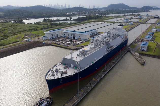
As the LNG trade has developed, and voyage lengths increased, the nominal size for LNG carriers has increased to approximately 175 000 m3 capacity. For specialised trade routes, ships of between 210 000 and 266 000 m3 are also in service.
In more recent years there have also been a few smaller scale LNG carriers, built with between 1 500 and 27 000 m3 capacity and with Type C tanks. Several of these small scale LNG carriers, in the form of both self-propelled ships and non-propelled barges, are being purpose built for the transport and transfer of LNG bunkers for non-gas carriers. These vessels follow the same principles as the larger gas carriers and, if used for international trade, must adhere to the requirements of the IGC Code.
All LNG ships have double hulls throughout their cargo length, which provide adequate space for ballast. Ships fitted with membrane tank systems have a full secondary barrier, while ships with Type B tanks have a drip-pan type protection.
Regasification vesels (RVs)
A regasification vessel (RV) combines the functions of on LNG carrier and regasification (regas) facilities. The ship is a conventional LNG carrier during the voyage and is then used as a regas terminal when discharging, be it alongside a dock or offshore at a submerged buoy.
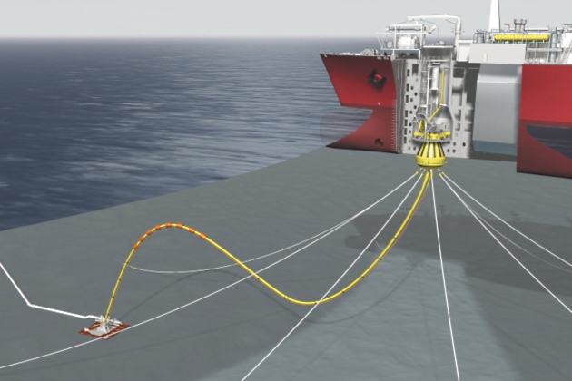
The regasification system on an RV is similar to the system installed on an FSRU, and is further discussed in article “Cargo equipment for gas carriers carrying LNG/LPGRegasification Units“. It utilises high pressure pumps and vaporisers to convert the LNG into gas for the shore grid. Seawater is used as the heating medium in the vaporisers. Steam can be used to heat the seawater if the ambient seawater temperature is low.
If utilised, the turret mooring system is similar to those used on FPSOs for crude oil operations. The LNG RV weathervanes to minimise the external environmental load when moored to the submerged buoy. The regasified natural gas is supplied from the RV, via a subsea manifold, through an onboard flexible piping system, swivel, submerged buoy, and subsea piping.
The LNG cargo tanks are based on conventional containment systems, but may be reinforced to allow for any tank liquid level during regas operations (see article “Preparation of loading and unloading operations for LNG/LPG carriersSloshing“). In an emergency situation the turret can be quickly disconnected from the submerged buoy and the LNG RV can evacuate to a safe location.
Gas Carrier Layout
Gas carriers have many features that are not found on other ship types designed for the carriage of bulk liquid cargo.
Article “Cargo equipment for gas carriers carrying LNG/LPGThe Ship – Cargo Equipment” deals specifically with cargo handling systems and highlights some of the basic differences. The unique features can be identified from the general arrangement of gas carriers, some of which are outlined in this section.
Cargo tanks on gas carriers are not designed for the carriage of ballast so separate ballast tanks are required.
The IGC Code does not permit a cargo pumproom to be placed below the upper deck, nor does it permit cargo pipelines to be run beneath deck level. Therefore, pipelines to and from the cargo tanks will be taken through a cargo tank dome (liquid or gas dome) that penetrates the deck (see article “Cargo equipment for gas carriers carrying LNG/LPGCargo pipelines“).
Read also: Liquefied Natural Gas Fundamental Knowledge and Understanding
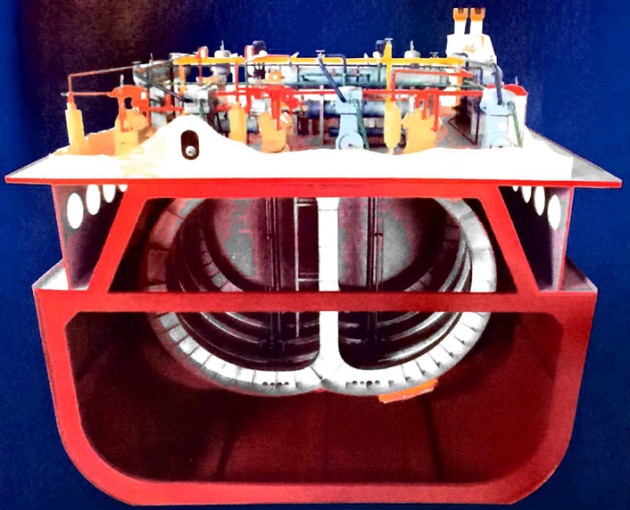
Where ships are fitted with a reliquefaction plant it is located in a compressor house on deck. Traditionally, an electric motor room containing the machinery driving the reliquefaction compressors would be adjacent to the compressor house and the connection between the motors and compressors would be made through a gas-tight bulkhead seal (see figure 11 for the most common arrangement). However, the most recent version of the IGC Code Code, the 2016 Edition, does allow for alternatives to this layout, such as the use of certified safe electrical motors installed in a combination compressor/ motor room.
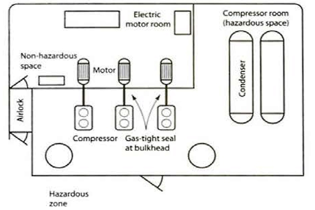
The IGC Code details the requirements for mechanical ventilation of these rooms. It states that positive pressure ventilation must be provided for the electric motor room and negative pressure ventilation for the cargo compressor area to ensure an appropriate pressure differential between the rooms.
An airlock entrance fitted to the electric motor room from the ship’s deck, which is required by the IGC Code to consist of two gas-tight doors at least 1,5 metres apart (but not more than 2,5 metres apart), is intended to prevent loss of air pressure upon entry into the motor room. To ensure that both doors are not opened simultaneously, the IGC Code requires that they must be self-closing, with audible and visual alarms on both sides of the airlock.
Another safety Feature set out by the IGC Code which is associated with the compressor room area is the sealing of drive shafts that penetrate the gas-tight bulkhead between the compressor and motor room. This is discussed further in article “Cargo equipment for gas carriers carrying LNG/LPGThe Ship – Cargo Equipment“.
The IGC Code requires that containment and handling systems be completely separate from the accommodation and machinery spaces. The IGC Code requires there to be a cofferdam, or other means of gas-tight segregation, between the cargo area and the engine room and fuel tanks. The IGC Code also gives specific advice for positioning doors that lead from accommodation spaces into cargo areas.
The IGC Code also provides that air intakes for accommodation and engine spaces must be sited away from cargo vent risers and all air intakes into accommodation and service spaces should be fitted with closing devices.
Gas carriers are fitted with a fixed water spray system for fire protection purposes. This covers areas
such as:
- Cargo tank domes and exposed cargo tank areas above deck;
- cargo manifold areas;
- the front of the accommodation, including lifeboat and muster stations facing the cargo area;
- cargo control room bulkheads facing the cargo deck.
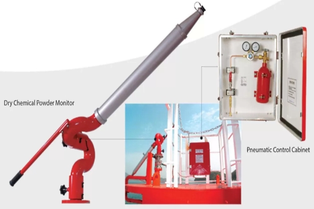
The IGC Code requires that minimum water flow rates of 10 litre/m2 per minute for horizontal surfaces, and 4 litre/m2 per minute for vertical surfaces, be achieved. In addition to the fixed water spray systems, the IGC Code requires that oil gas carriers be fitted with a fixed dry powder installation capable of fighting fires in the cargo area. The IGC Code requires at least two handheld hoses or a combination of monitor/hand hose lines to be provided to cover the deck area.
A monitor, capable of being actuated both locally and remotely, is also required by the IGC Code to be fitted to protect any load/unload connection area. For ships larger than 1 000 m3 cargo capacity two independent, self-contained dry powder units are required by the IGC Code to be fitted (ships of less than 1 000 m3 capacity are only required to have one unit). The dry powder installation is commonly actuated by nitrogen pressure, which is stored in cylinders adjacent to the powder containers.
Hazardous Zones
The primary goals of gas carrier design are the elimination of the likelihood of an explosive gas atmosphere occurring and elimination of the sources of ignition in areas where explosive gas atmospheres may occur.
Where it is not possible to fully apply these principles, equipment, systems and procedures may be selected and prepared so that the likelihood of the coincidence of an explosive gas atmosphere and an ignition source is made as small as reasonably practicable.
All areas where cargo vapour is likely to occur, in concentrations that are within the cargo’s flammable range, ought to be considered as hazardous areas. Any equipment installed or used in such areas will, therefore, need to be suitable for use in hazardous locations. While the IGC Code defines certain areas on gas carriers as hazardous, each design will be reviewed for proper designation of hazardous area classification.
Hazardous area clossification
Hazardous area classification is a method of analysing and classifying the environment where explosive gas atmospheres may occur. Its main purpose is to allow for the proper selection and installation of equipment that can be used safely in that environment, taking into account the properties of the flammable materials that will be present.
Area classification also allows for the preparation of safety procedures for system operation and maintenance. The international standard that guides zone classification studies for flammable gas and vapour atmospheres is the International Electrotechnical Commission (IEC) Standard 60079-10-1 (Reference 2.10). Note that the application of IEC 60079-10-1 to ships is further discussed in IEC 60092-502, Electrical Installations in Ships. Tankers – Special features (Reference 2.11). See also point “Liquefied Petroleum Gas Reliquefaction Plant and Boil-Off ControlCargo Instrumentation“, regarding electrical equipment installations.
IEC definitions
Hazardous areas are classified into zones based on an assessment of the frequency of occurrence, and the likely duration, of an explosive gas atmosphere. The definitions found in IEC 60079-10-1 are:
Explosive atmosphere
Mixture with air, under atmospheric conditions, of flammable substances in the form of gas, vapour, dust, fibres or ayings which, ofter ignition, permits self-sustaining flame propagation.
Explosive gas atmosphere
Mixture with air, under atmospheric conditions, of flammable substances in the form of gas or vapour which, after ignition, permits self-sustaining flame propagation.
Hazardous area
An area in which an explosive gas atmosphere is or may be expected to be present, in quantities that require special precautions for the construction, installation and use of equipment.
Zone 0
An area in which an explosive gas atmosphere is present continuously or for long periods or frequently. Note: Both “long” and “frequently” are intended to describe a very high likelihood of a potentially explosive atmosphere in the area. In that respect, those terms do not necessarily need to be quantified.
Zone 1
An area in which an explosive gas atmosphere is likely to occur periodically or occasionally in normal operation.
Zone 2
An area in which an explosive gas atmosphere is not likely to occur in normal operation but, if it does occur, it will exist for a short period only.
Non-hazardous area (safe area)
An area where an explosive atmosphere is not expected to be present in quantities such as to require special precautions for the construction, installation and use of equipment.
Zone determination
The size of the zone depends on the estimated area/distance over which a gas/air mixture exists before it is diluted by air to a concentration below its lower flammable limit (LFL). The greater the release rate of the gas or vapour, the larger the extent of the zone. The size of the resulting cloud mixture of flammable gas or vapour with air, and the time for which it persists after a release is stopped, can be influenced by ventilation.
In general, the number and extent of Zone 0 and Zone 1 areas will be minimised by design or suitable operating procedures. In other words, plant and installations will be mainly Zone 2 or non-hazardous. Where necessary, the design, operation and location of process equipment will ensure that, even when it is operating abnormally, the amount of flammable substance released into the atmosphere is minimised so as to reduce the extent of the hazardous area.
The issue of managing toxic gases is slightly more complex as the IEC standard was not designed to provide mitigation against toxic gases. However, where a gas is both toxic and flammable, a hazardous area classification highlights spaces where gases can accumulate and, therefore, depending on the cargo, may require special precautions for entry and/or access. Hazardous area classification is performed by applying first principles and goes beyond the prescriptive definition of spaces where “certified safe” equipment must be installed. This process will, therefore, identify all spaces where gas may accumulate, regardless of its toxicity or flammability.
Ventilation
Where there is sufficient ventilation in an enclosed space, the hazards can be treated in the same manner as they would be in open air and the zones will not, therefore, be considered to fill the whole of the enclosed space but will rather be zones of designated radii centred on the source of potential release of gas or vapour. This may still cause the zones to be of a greater extent than is practical for the design but the standard allows the philosophy of ventilation to be token further. By further increasing the ventilation the extent of the hazardous zones can be reduced. This does require a proper assessment of the rotes of release, as the standard states “the higher the amount of ventilation in respect of the possible release rates, the smaller will be the extent of the zones (hazardous areas), in some cases reducing them to a negligible extent (non-hazardous area)“.
It is important not to confuse the roles of ventilation and gas detection. Ventilation is the means by which the space can be considered non-hazardous under normal operating conditions as well as foreseeable abnormal conditions. Ventilation equipment and systems in such service need to be designed for a high availability.
Gas detection under ventilated conditions is, theoretically, not needed but provides an additional layer of safety. The IGC Code requires gas detection be installed to “monitor the integrity of the cargo containment, cargo handling and ancillary systems“. See point “Liquefied Petroleum Gas Reliquefaction Plant and Boil-Off ControlGas detection system” for a further discussion on gas detection systems.
Survival Capability
The IGC Code divides all gas carriers into four categories, ship Types 1G, 2G, 2PG and 3G, according to the hazard rating of the cargoes that the ship is certified to carry. In the IGC Code, for example, Type 1G ships (where the cargo tanks are located at the greatest distance from the side shell and which may also be restricted in capacity) must be used for cargoes representing the greatest hazard, such as chlorine. Ship Types 2G/2PG and 3G can carry cargoes that represent progressively decreasing environmental hazards and, therefore, the IGC Code provides for progressively less stringent structural requirements in respect of damage survival capability in the event of collision or grounding.
Under the IGC Code, a fully-refrigerated ship with Type A tanks (see point “Type A tanks” below) and designed for LPG would need to comply with certain requirements for tank location and survival capability of a category 2G ship, while a semi-pressurised ship, with Type C tanks carrying LPG, could, under the IGC Code, comply with the requirements of either a 2G or a 2PG ship. In the case of a 2PG ship, the Type C pressure vessels are required by the IGC Code to have a design pressure of at least 7 bar and a design temperature not lower than minus 55 °C (-55 °C) and a maximum length overall of 150 m. This is because the 2PG category takes into account the fact that the pressure vessel design provides increased survival capability if the ship is damaged by collision or grounding.
The IGC Code and Classification Society rules contain the full construction requirements and should always be referred to for the detailed requirements for each category of ship.
Surveys and Certification
Certificate of fitness
A ship certified to comply with an older IMO Gas Code (Existing Ship or GC Code) will be surveyed and, if it meets the relevant requirements, be issued with a “Certificate of Fitness for the Carriage of Liquefied Gases in Bulk”. Where the ship is designed in accordance with the IGC Code, then the certificate is called the “International Certificate of Fitness for the Carriage of Liquefied Gases in Bulk”.
These certificates signify that a minimum standard of constructional safety has been incorporated into the ship’s build and will list the cargo grades that the ship is certified to carry and the carriage condition or minimum tank temperature.
To comply with the relevant Gas Code a gas carrier must be re-surveyed periodically to ensure the continuing validity of the Certificate of Fitness.
Surveys required to maintain the validity of the Certificate of Fitness are:
- An Initial Survey before the ship enters service (after which an Interim Certificate is issued);
- a Renewal Survey before the end of a period not exceeding five years (after which a new Certificate of Fitness is issued);
- an Intermediate Survey (half way between each Renewal Survey);
- an Annual or Periodic Survey relevant to a specific statutory certificate;
- an Additional Survey after a serious accident or important renewals;
- a periodic docking, twice in any five year period, one of which may be performed in water subject to satisfactory approval of the vessel for In-Water Survey.
The scope of each survey depends on the age of the liquefied gas carrier and, to some extent, the containment system used in the ship’s construction.
In addition to the survey requirements of the IGC Code, a gas carrier will also require surveys to validate standard cargo ship statutory certificates.
Carriage of noxious liquid substances (NLS)
A number of LPG carriers are certified to carry chemical products that have a vapour pressure not exceeding 2,9 bara at a temperature of 37,8 °C and which products are, consequently, not a gas as per the IGC Code definition. These products are called noxious liquid substances and are recognised as presenting a hazard to human health or marine life.
Products designated as NLS are listed in the IGC Code and are also included in the IBC Code. LPG carriers certified for any of these products will have them detailed on the ship’s International Pollution Prevention Certificate for the carriage of Noxious Liquid Substances, often referred to as the NLS Certificate.
In addition to the Certificate of Fitness, which lists all liquefied gas products that the ship is certified to carry, a vessel certified to carry an NLS must comply with MARPOL Annex II and have the following additional documents onboard:
- International Pollution Prevention Certificate;
- a Procedures and Arrangements Manual, describing the operational procedures that must be followed in order to comply with MARPOL Annex II;
- a Cargo Record Book, as per MARPOL Annex II requirements;
- a Shipboard Marine Pollution Emergency Plan (SMPEP), covering accidental spills or release of NLS.
See also point “Properties of liquefied gasesFormation of polymers or dimers“, regarding the inhibitor information form, and point “Properties of liquefied gasesFlammability/flammable range“, regarding Rome screens that are required to be in place when carrying NLS cargoes.
Materials of Construction and Insulation
Construction materials
The choice of cargo tank materials is, in the main, dictated by the minimum service temperature and, to a lesser degree, by compatibility with the cargoes carried. The most important property to consider in the selection of cargo tank materials is the low temperature toughness, because many metals and alloys become brittle below a certain temperature.
Treatment of structural carbon steels can be used to achieve low temperature characteristics and the IGC Code specifies low temperature limits for varying grades of steel. Reference should be made to the IGC Code and to Classification Society rules for details on the temperature limits and compositions of various grades of steel.
It will be interesting: Gas laws, thermodynamic principles and reliquefaction
According to the IGC Code, ships carrying fully-refrigerated LPG cargoes may have tanks capable of withstanding temperatures down to minus 55 °C (-55 °C). The final temperature is usually chosen by the ship operator, depending on the cargoes expected to be carried. This is often determined by the boiling point of liquid propane at atmospheric pressure, so cargo tank temperature limitations are frequently set at approximately minus 46 °C (-46 °C). For semi-refrigerated ships the reference would be liquefied propylene, with a corresponding boiling point at atmospheric pressure of minus 48 °C (-48 °C). To achieve these service temperatures, steels such as fully killed (steel with all oxygen removed), fine grain, carbon-manganese steel, sometimes alloyed with 0,5 % nickel, are used. These low temperature steels may require specialist welding procedures and heat treatment to achieve the desired material characteristics.
Where a ship has been designed specifically to carry fully-refrigerated ethylene (with a boiling point at atmospheric pressure of minus 104 °C (-104 °C)) or LNG (atmospheric boiling point minus 162 °C (-162 °C)), nickel-alloyed steels, stainless steels or aluminium will be used for tank construction.
Tank insulation
Thermal insulation is fitted to refrigerated cargo tanks for the following reasons:
To minimise heat flow into cargo tanks and reduce boil-off; to protect the ship structure around the cargo tanks from the effects of low temperature.
Insulation materials for use on gas carriers will usually possess the following main characteristics:
- Low thermal conductivity;
- ability to bear loads;
- ability to withstand mechanical damage;
- light weight;
- unaffected by cargo liquid or vapour.
The vapour sealing property of the insulation system is important to prevent the ingress of water or water vapour. Ingress of moisture can cause a loss of insulation efficiency and progressive condensation and freezing can cause extensive mechanical damage to the insulation. Humidity conditions will, therefore, be kept as low as possible in hold spaces. One method used to protect the insulation is to provide a foil skin that acts as a vapour barrier to surround the system.
| Table 1. Typical insulation material conductivities at 20 °C | ||
|---|---|---|
| Material | Application | Thermal Conductivity Milliwatts per Metre Kelvin at 20 °C |
| Balsa wood | A load bearing insulant of varying density | 42 to 55 |
| Mineral wool | Normally supplied in slobs or rolls of various densities | 32 to 40 |
| Perlite | Granular silicon/ aluminium oxide used as bulk in-fill for hold spaces or in modular boxes | 38 to 42 |
| Polystyrene | Pre-formed extruded, various blowing agents and densities | 26 to 30 |
| Polystyrene | Pre-formed expanded, various densities | 31 to 32 |
| Polyurethane | Pre-formed, sprayed or foamed, various blowing agents and densities | 22 to 33 |
Thermal insulation may be applied to various surfaces, depending on the design of the containment system. For Type B and Type C containment systems, insulation is applied directly to the cargo tank’s outer surfaces. For Type A cargo tanks, insulation can be applied either directly to the cargo tank or to the inner hull (if fitted) although, for maximum effectiveness, it is more common for the insulation to be applied directly to the cargo tank surface.
Because of its open grain structure, balsa wood has very good thermal insulation properties when compared with other timbers and was often used in one of the early LNG containment systems, both freestanding and membrane designs. Unfortunately, if the timber ignites the open grain structure has both a comparatively high charring rate and a rapid rate of surface flame spread. Balsa also has the capability to absorb several times its own weight of water and, therefore, has the ability to absorb large quantities of petroleum liquids or vapour. For these reasons, balsa wood is no longer used in cargo containment systems.
Cargo Containment Systems
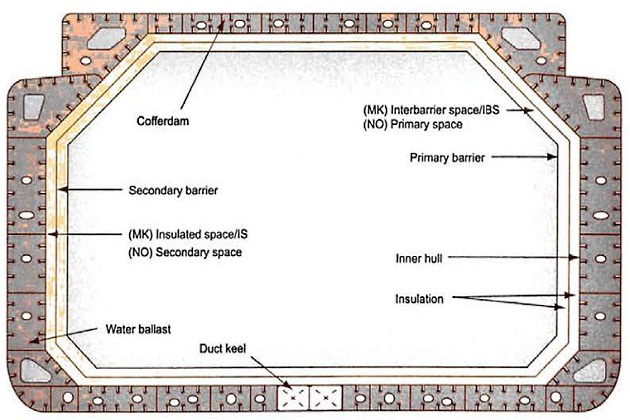
A cargo containment system includes, where fitted, a primary and secondary barrier, associated insulation and any intervening spaces and any adjacent structure that may be necessary for the support of these elements.
For cargoes carried at temperatures between minus 10 °C (-10 °C) and minus 55 °C (-55 °C), the ship’s hull may, subject to the IGC Code requirements, act as the secondary barrier and, in such cases, it may be a boundary of the hold space.
The basic cargo tank types utilised on board gas carriers are as follows:
- Independent Type A;
- independent Type B;
- independent Type C;
- membrane.
The independent tanks (Type A, Type B and Type C) are completely self-supporting and do not form part of the ship’s hull. However, structurally they introduce loads and forces that will need to be accommodated for in the design, so they influence the structural design of the ship but do not contribute to hull strength.
| Table 2. Main cargo containment systems comparison | ||||||
|---|---|---|---|---|---|---|
| Charactersties | Type A Prismatic | Type B Prismatic (SPB) | Type B Spherical (Moss) | Type C | Membrane | |
 |  |  |  |  | ||
| Benefits | Very robust | Very robust | Very robust | Single hull construction acceptable | Extensive experience for LNG carriers | |
| centreline bulkhead prevents sloshing | centreline bulkhead prevents sloshing | centreline bulkhead prevents sloshing | very robust | typically low boil-off rate (BOR) | ||
| partial secondary barrier | centreline bulkhead prevents sloshing | |||||
| no partial filling limitations | no secondary barrier required | |||||
| no free surface effect | ||||||
| Limitations | Requires an independent secondarybarrier | Limited number of shipyards licensed to fabricate | Less cargo capacity for same physical size of ship | Less attractive for very large capacities (cost/ weight) | Limited impact resistance | |
| height of tanks affects forward visibility from wheelhouse | less space efficient | full width tanks prone to sloshing | ||||
| partial filling restrictions unless rei nforcements applied | ||||||
Type A tanks
Type A tanks are primarily constructed of flat surfaces. Under the IGC Code, the maximum allowable lank design pressure in the vapour space for this type of system is 0,7 bar. This means that cargoes will be carried in a fully-refrigerated condition, al or near atmospheric pressure (normally below 0,25 bar).
| Table 3. IGC Code requirements for secondary barriers in relation to cargo containment tank types | |||
|---|---|---|---|
| Cargo Temperature at Atmospheric Pressure | -10 °C and Above | Below -10 °C Down to -55 °C | Below -55 °C |
| Basic tank type | No secondary barrier required | Hull may act as secondary barrier | Separote secondary barrier where required |
| Integral | Tank type not normally allowed | ||
| Membrane | Complete secondary barrier | ||
| Semi-membrane | Complete secondary barrier | ||
| Independent: | |||
| Type A | Complete secondary barrier | ||
| Type B | Partial secondary barrier | ||
| Type C | No secondary barrier required | ||
| The full requirements are set out in the IGC Code, which should always be consulted in preference to this publication. For additional information, please refer to Chapter 4 of the IGC Code – Cargo Containment. | |||
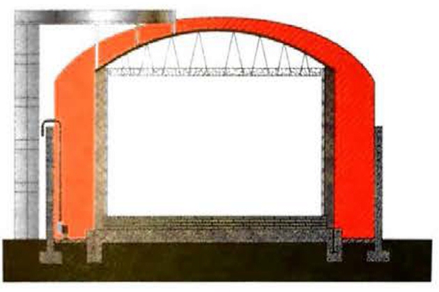
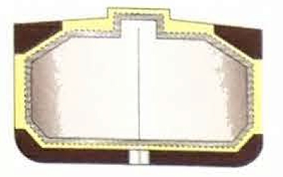
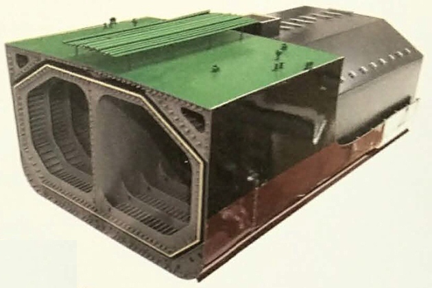
A Type A tank is a self-supporting prismatic tank that requires conventional internal stiffening in Figure 17 the tank is surrounded by a skin of foam insulation. The typical arrangemenl is shown in Figure 17, with the tank covered by a skin of foam insulation. In some simpler, less efficcient arrangements, perlite insulation is used, filling the hold space completely.
The material used for Type A and Type B tanks is the same. Type A tanks are not designed on the “leak before failure” concept used for Type B tanks. Therefore, to ensure safety in the unlikely event of cargo tank leakage, a secondary containment system is required under the IGC Code.
This secondary containment system is known as a secondary barrier and is a feature of all ships with Type A tanks are cappable of carrying cargoes below minus 10 °C (-10 °C).
For a fully-refrigerated LPG carrier (which will not carry cargoes below minus 55 °C (-55 °C)) the secondary barrier is required by the IGC Code to be a complete barrier capable of containing the whole tank volume at a defined angle of list. It may form port of the ship’s hull, which is the most commonly adopted design approach for this type of vessel, and it means that certain areas of the ship’s hull will be constructed of special steel capable of withstanding low temperatures. The alternative is to build a separate secondary barrier around each cargo tank. A secondary barrier, separate from the hull, is required by the IGC Code for Type A tanks designed to carry cargoes below minus 55 °C (-55 °C), such as ethane or LNG.
The space between the cargo tank (sometimes referred to as the primary barrier) and the secondary barrier, ie the outer hull, is known as the hold space. When flammable cargoes are being earned these spaces are required by the IGC Code to be filled with inert gas. This is to prevent a flammable atmosphere being created in the event of primary barrier leakage.
Type B tanks
Type В tanks can be constructed of flat surfaces or they may be of the spherical type. This type of containment system is the subject of much more detailed stress analysis than Type A systems.
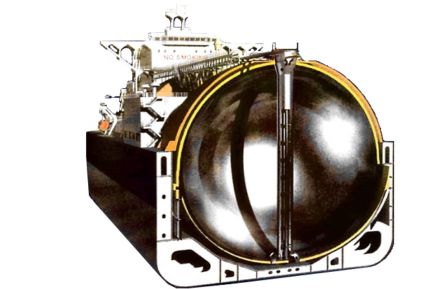
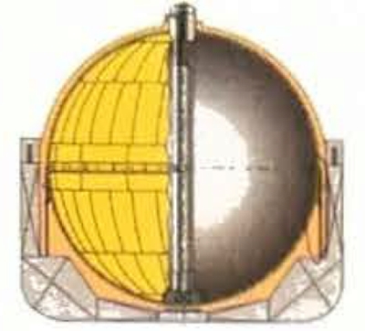
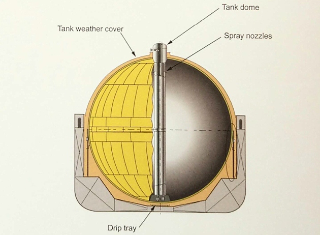
The most common arrangement of Type В tank is a spherical tank, known as the Moss type. The spherical shell is normally made of aluminium and the support system is an equatorial ring, at mid-level height, that connects the shell to the cylindrical skirt, which in turn is supported on the inner hull. There is a continuous system of channels between the insulation and the shell surface which is continuously purged with nitrogen and monitored by gas detection.
Any leakage due to cracks in the shell will, therefore, be quickly detected and will drain down into the drip tray below the tank’s south pole (ie underneath the tank). This drip tray only has to contain the very small, maximum credible, leak that may be envisioned by the “leak before failure” design, and constitutes the partial secondary barrier, in accordance with the IGC Code.
On Moss type designs the space between the tank and the insulation is purged with inert gas, but the hold space is only filled with inert gas in the event of gas detection. Generally, the hold spaces are filled with dry air to avoid any ingress of moisture, as this moisture can contribute to the formation of cold spots on the tank’s outer surface.
The Type В spherical tank is almost exclusively applied to LNG ships and it seldom features in the LPG trade.
The first Moss design (Moss Rosenberg), which was completed in 1973, was the Norman Lady at 87 600 m3. It was followed by a series of Moss design ships at 29 000 m3.
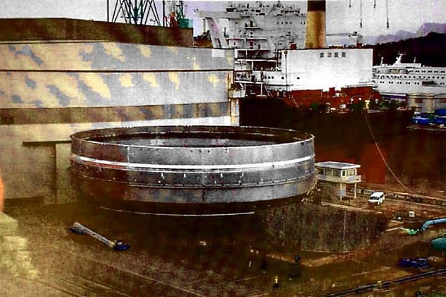
(To increase the volume without increasing hull dimensions, the Moss tank can be constructed in a “stretched version” where a cylindrical section is inserted in the equatorial area)
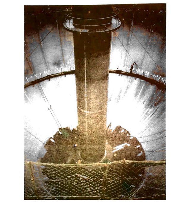
There are some variations in the design of spherical Type B tanks, depending on where and when they were constructed. Notable differences, some of which can impact on cool-down times in particular, are:
- Support of the central pipe tower and its attachment arrangement top and bottom;
- the shape of the pipe tower base structure;
- insulation arrangement (spiral wound or a fixed panel system).
Due to the inherent strength of spherical Type B tanks, it may be possible for the allowable vapour pressure in calm/harbour conditions to be higher than the standard 0,7 bar, due to there being no vessel rolling motion that could impose dynamic liquid pressure on the cargo tank structures. Therefore, while not considered a normal operation in harbour condition it may be possible to discharge the liquid by pressure, in the order of 2,0 bar, to empty the tanks completely.
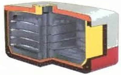
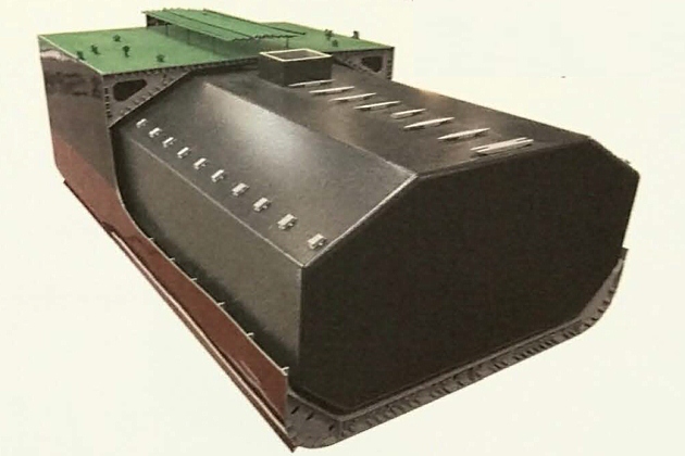
The prismatic Type B tank has the benefit of maximising ship hull volumetric efficiency and has the entire cargo tank placed beneath the main deck. Where the prismatic shape is used, the maximum design vapour space pressure is, as for Type A tanks, limited, under the IGC Code, to 0,7 bar.
Type C – tanks (semi refrigerated)
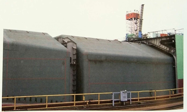
Type C tanks are normally spherical or cylindrical pressure vessels with design pressures higher than 2 bar. The cylindrical vessels may be vertically or horizontally mounted. This type of containment system is always used for semi-refrigerated gas carriers. In the case of the semi-refrigerated ships, it can also be used for fully-refrigerated carriage provided appropriate low temperature steels are used in tank construction. Type C tanks are designed and built to conventional pressure vessel codes and, as a result, can be subjected to accurate stress analysis. Design stresses are kept low. No secondary barrier is required by the IGC Code for Type C tanks and the hold space can be filled with either inert gas or dry air.
For a semi-refrigerated ship, the cargo tanks and associated equipment are designed for a working pressure of approximately 5 to 7 bar and a vacuum of 0,5 bar. Typically, the tank steels for the semi-refrigerated ships are capable of withstanding carriage temperatures as low as minus 104 °C (-104 °C), which is adequate for the range of LPG cargoes and is also suitable for ethylene and ethane.
Type C tanks (fully-pressurised)
In the case of a typical fully-pressurised ship (where the cargo is carried at ambient temperature), the tanks may be designed for a maximum working pressure of about 18 bar.
Type C tanks, when fitted in a typical fully- pressurised gas carrier, make a comparatively poor utilisation of the hull volume. However, this can be improved by using intersecting pressure vessels or bi-lobe type tanks, which may be designed with a taper at the forward end of the ship. This is also a common arrangement in semi-pressurised ships, as shown in point “Type C – tanks (semi refrigerated)” below.
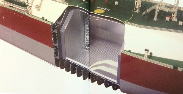
Membrane tanks
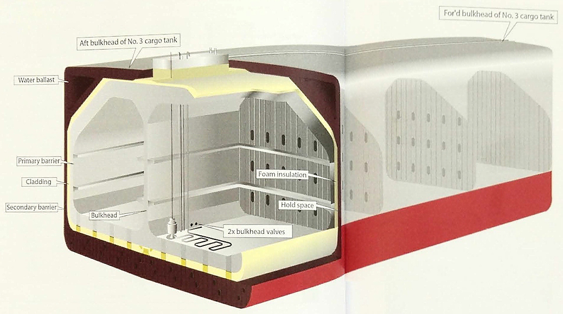
Unlike self-supporting independent tanks, membrane tanks utilise the inner hull of the ship as the primary load bearing structure. The main safety features incorporated into the design of a membrane LNG carrier, to prevent the low-temperature cargo coming into contact with and damaging the ship’s steel structure, are the double barriers of the containment system itself. Each barrier consists of a thin membrane that is made of material able to withstand and absorb thermal contraction and is backed by a layer of insulation. The membrane is designed in such a way that thermal expansion or contraction is compensated for without over-stressing the membrane itself.
The primary barrier (membrane of 0,7 to 1,5 mm thick) is the inner element that comes into contact with the cargo and is designed to contain that cargo. The distributions of the steel grades that are to form the inner hull are selected at the design stage by considering the worst possible environmental conditions and a full liquid cargo flooding of the primary space. The secondary barrier is design to contain any envisaged leak of liquid cargo through the primary barrier for a period of 15 days, as prescribed by the IGC Code. During this time the temperature on the double hull must not drop to or below a level that could cause brittle fracture of the steels used in the hull construction.
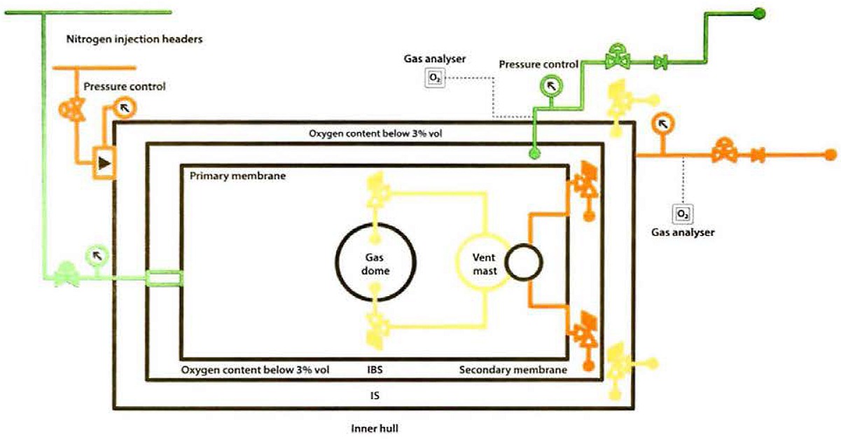
The insulation spaces in the membrane cargo containment system are monitored by temperature sensors to identify possible defects in the membrane. In addition, nitrogen is passed through these spaces continuously and is monitored for leakage by gas detectors before passing through a vent mast. If necessary, normal nitrogen flow can be increased to “sweep out” any gas concentrations.
The membrane designs primarily in use today are the NO 96 and MK III systems. Both systems are products of GTT (Gaztransport & Technigaz) following the merger of the two original licence holders (NO 96 system = Gaztransport, MK III = Technigaz).
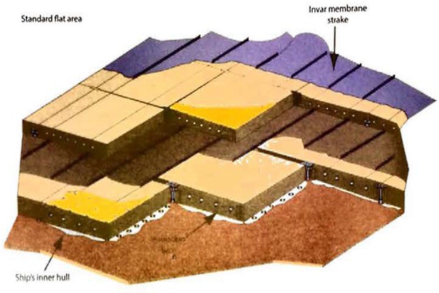
NO “type” containment system
The NO “type” containment system consists of a thin invar primary barrier.
Invar is a steel alloy containing about 36 % nickel and 0,2 % carbon. This is attached the inner (cold) surface of insulation filled plywood boxes used as the primary insula. The boxes have a thickness of between 200 and 300 mm and are attached to an ide inner layer of invar (the secondary barrier).
Finally, a further set of similar insulation boxes form the secondary insulation Invar is chosen for the membranes because of its very low coefficient of thermal expansion, making expansion joints, or corrugation, barriers unnecessary. The longitudinal resistance welds joining parallel strokes to anchor strips along the upturned edges of the strokes do, however, serve as expansion joint absorbing transverse loads, longitudinal loads are transmitted into the bulkhead stn via anchoring chairs or bors and box “tube” structures, depending on the membrane system being used. Later desings of the NO system utilise invar membranes of 0,7 mm thickness in strakes of 500 mm width in the flat panel areas, and strengthened plywood boxes to hold the insulation.
Read also: Regulations and Guidance for Liquefied Natural Gas Shipping
Figure 30 shows the standard Gaztransport NO 96 system that was fitted of LNG carriers built since 1992. Since this time, to increase load bearing strength, reduce boil-off and improve the integrity of the containment systems, a number of modifications were implemented on later generations of the NO 96 containment system.
Variations on the NO 96 system
Historically, perlite has been used as insulation on the NO 96 system. The perlite is processed with silicone to make it impervious to water or moisture.
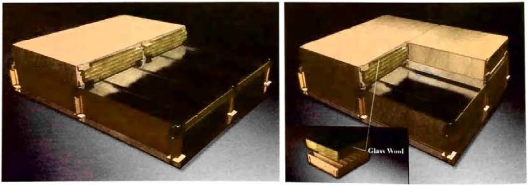
The perlite powder may be replaced with glass wool to provide for lower boil-off rates (BORs) (to between 0,125 % and 0,13 % per day).

The thickness of the insulation boxes can be adjusted to obtain the required BOR. To further improve the thermal efficiency and achieve lower BORs, the usual two box layers may be replaced in this variant by three layers totalling the same thickness. The primary insulation consists of a glass wool filled box. The secondary insulation consists of a rigid polyurethane foam (RPU) panel combined with a glass wool filled box. This provides improved insulation efficiency, with a reduced BOR of between 0,105 % and 0,11 % per day.
Strength enhancement – NO 96
To meet requirements for higher sustained loads, a set of different boxes corresponding to different levels of reinforcement can be provided by changing the thickness and/or number of the wooden components making up the boxes.
Mark (MK) membrane system
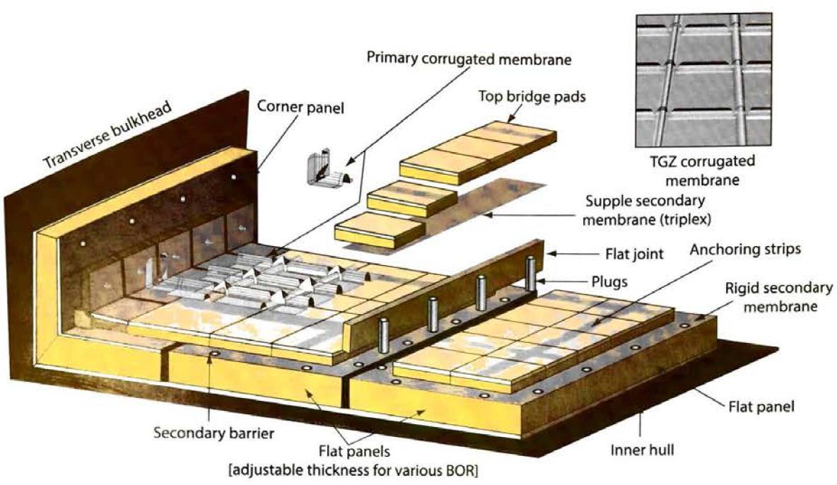
The Technigaz Mark system, shown in Figure 33, features a primary barrier of stainless steel ( 1,2 mm in thickness) with raised corrugations, or “waffles“, to allow for expansion and contraction. Adjacent panels are overlapping and welded to give membrane continuity and integrity.

The corrugated panels are secured to the primary insulation by tack welding to stainless steel inserts set into the primary insulation surface. In the original MK I design, the insulation that supports the primary membrane consisted of laminated balsa wood panels held between two plywood layers; the face plywood forming the secondary barrier. The balsa wood panels were interconnected with specially designed joints and were supported on the inner hull of the ship by wooden grounds.

In the latest design (MK III) the balsa wood insulation is replaced by reinforced cellular foam. Attached to the foam is a fibreglass cloth/aluminium laminate, known as triplex, acting as the secondary barrier. The secondary barrier integrity between panels is maintained by “flexible” triplex sheets, glued in place between the triplex membrane, which are sandwiched between primary and secondary insulation of the panels.

In both membrane designs the load upon the insulation system is transmitted into the hull structure by “resin ropes” that are laid under the insulation panels to smooth out irregularities in the hull structure plating and, once set hard, provide structural continuity between insulation and inner hull structure.
The first MK III LNG carrier entered service in 1993 and she was the 18 800 m3 Aman Bintulu.
Mark III “Flex”
To meet requirements for lower boil-off and systems sustaining higher loads, the insulation thickness of the MK III system can be increased and the RPU foam can be reinforced by adding more glass fibres. Other modifications are made to the system, including the addition of “dimples” to the sides of the corrugations to avoid collapse, the addition of strengthening wedges placed under the corrugations, an increase in the foam density resulting in a higher compressive strength and improvements in the bonding of the system components.
The increase in foam density doubles the strength of the panels but also raises the thermal conductivity, so the thickness of the panels needs to be increased to obtain the conventional 0,15 % per day BOR. However, where standard density foam has been combined with a higher thickness of foam, a reduction in BOR will usually result, corresponding to 0,1 % per day BOR, or less.
Semi membrane containment system
The semi-membrane containment system is a variation of the membrane containment system. The primary barrier is much thicker than in the membrane system, having flat sides and large radiused corners. The tank is self-supporting when empty but not in the loaded condition. In this condition the liquid (hydrostatic) and vapour pressures acting on the primary barrier are transmitted through the insulation to the inner hull, as is the case with the membrane system. The corners and edges are designed to accommodate expansion and contraction.
Although semi-membrane tanks were originally developed for the carriage of LNG, no commercial size LNG carrier has yet been built to this design. The system was, however, adopted for use in LPG ships and several vessels, currently no longer in service, were built to this design.
Integral tanks
Integral tanks form a structural part of the ship’s hull and are influenced by the same loads that stress the hull structure. Integral tanks are not normally allowed for the carriage of liquefied gas if the cargo temperature is below minus 10 °C (-10 °C). Certain tanks on a limited number of Japanese built LPG carriers are of the integral type and they are used for the dedicated carriage of fully-refrigerated butane.