This article covers gas carrier cargo handling equipment and related instrumentation. It reviews pipeline and valve design issues and considers cargo pumps and ancillary equipment, including inert gas generators.
- Cargo Pipelines and Valves
- Cargo pipelines
- Hazards of cargo line pressure testing
- Cargo strainers
- Emergency shutdown (ESD) systems
- Effect of surge pressure should FSD activate
- Relief valves for cargo tanks and pipelines
- Types of pressure relief valves
- Cargo Pumps
- Pump performance curves
- Deepwell pumps
- Submerged motor pump
- Booster pumps
- Ice prevention at cargo pumps
- Emergency cargo pump
- Cargo Heaters
- Direct cargo heaters
- Indirect cargo heaters
- Cargo Vaporisers
- Regasification Units
- Closed loop with steam heating
- Combined open/closed loop with seawater and steam heaiing
- Closed loop with steam heating and intermediate water/g lycol loop
- Open loop with seawater heating and intermediate propane loop
The plant associated with cargo reliquefaction is also described, along with some of the special operational and maintenance issues.
Cargo Pipelines and Valves
Cargo pipelines
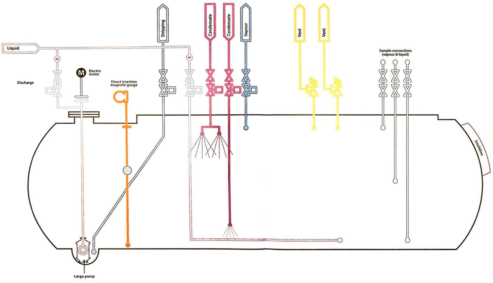
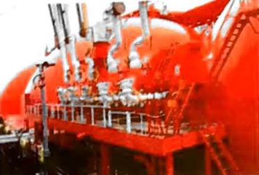
Gas carriers are usually fitted with liquid and vapour manifolds that are, ideally, situated amidships. The manifolds are connected to liquid and vapour headers, or pipelines with branches leading into each cargo tank. The liquid loading line is led through the tank dome to the bottom of each cargo tank and the vapour connection is taken from the top of each cargo tank. On semi-refrigerated and gas carriers that reliquefy the cargoes (fully-refrigerated liquefied petroleum gas (LPG) and some liquefied natural gas (LNG) carriers) a vapour connection is taken from the vapour header to the cargo compressor room, where reliquefaction of the cargo boil-off takes place. After reliquefaction the cargo is piped, via a condensate return line, to each cargo tank. Newer LNG carriers, which may also serve as floating storage units (FSUs) or floating storage and regasification units (FSRUs) or regasification vessels (RV), may have discharge manifolds located elsewhere for a specific service. RVs, for example, may have a turret manifold mounted towards the bow of the vessel in addition to the traditional manifold. Some FSRU designs may also have a top fill line to at least one cargo tank.
The IGC Code does not permit cargo pipelines below deck level on gas carriers, so all pipe connections to tanks will be taken through the cargo tank domes that penetrate the main deck. Vapour relief valves are also fitted on the tank domes and these are piped, via a vent header, to the vent riser. The vent risers are fitted at a safe height and safe distances from accommodation spaces and other such gas-safe zones, as is specified in the IGC Code.
The IGC Code requires that “all pipelines or components which may be isolated in a liquid full condition shall be protected with relief valves for thermal expansion and evaporation“.
In practice, this means all sections of liquid lines that may be isolated are fitted with protection, but vapour-only lines may not be so equipped. While the circumstances where liquid may accumulate in vapour lines are very unusual, it is important for operators and designers to understand the implications and to be alert for the possibility. This is particularly important for vapour lines that may see intermittent service and, when not in service, may be isolated with locked-in sections. Mitigation measures may include steps such as installation of low temperature and/or high pressure alarms, or changes to operating procedures in the cargo operations manuals to ensure that valves are not dosed to lock-in a section until temperatures have stabilised.
It will generally be appropriate for provision to be made in the design and fitting of cargo pipelines, to allow for thermal expansion and contraction. This is best achieved by fitting expansion loops or by using the natural geometry of the pipework, whichever is appropriate. Expansion bellows, fabricated from corrosion resistant materials and meeting the design and installation requirements of the IGC Code, may be used on pipelines outside of the cargo tanks if pipe bends or expansion loops are not practical. Where expansion bellows are fitted in vapour lines it is prudent to ensure that their pressure rating at leost meets the liquid pipeline design criteria. Expansion bellows are often subject to a considerable amount of wear and tear while a ship is in service and, in particular, seawater corrosion should be carefully avoided as pinhole leaks are likely to develop.
In addition to pipeline supports, which are an integral part of the pipeline expansion arrangements, pipeline systems are fitted with strong anchor points to resist lateral or vertical displacement from surge pressures. When replacing ports such as bolts, slide bearing plates and restraining rods, care should be taken to ensure that the new parts are of the correct material for the service.
Removable spool pieces are taken in or out of pipelines to interconnect sections of line for special operational reasons, such as using the inert gas plant or ensuring segregation of incompatible cargoes. Generally, these spool pieces should not be left in position ofter use, but should be removed and pipelines blanked to ensure positive segregation.
Hazards of cargo line pressure testing
On oil tankers, following a number of pollution incidents due to leakage, typically as a result of corrosion of the pipework, it become usual practice to pressure test bunker transfer lines. This practice of pressure testing lines has been extended to all deck cargo lines on oil tankers and lines are pressure tested to a defined pressure, usually once per year.
The pressure testing, which is reasonably easy to implement on an oil tanker, is a pollution protection measure aimed at minimising the leakage of MARPOL Annex I cargoes and is a requirement in the ship inspection report (SIRE) and the vessel particulars questionnaire (VPQ) for oil tankers, but not for gas carriers.
Liquefied gases are not MARPOL Annex I cargoes, so the annual pressure testing of cargo lines on liquefied gas carriers is not generally necessary.
The IGC Code states that, for gas ships, the design pressure for deck liquid lines should not be less than 10 bar.
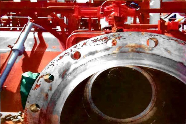
Reducers and spool pieces for gas carriers will usually be supplied in accordance with the requirements of the trade. Further guidance on the layout, strength and fittings for gas carrier manifolds can be found in SIGTTO’s “Manifold Recommendations for Liquefied Gas Carriers” (Reference 2.13).
Reducers and spool pieces are required to meet the wide range of presentation flange requirements of existing terminals without exceeding the maximum allowable design forces.
Whenever possible, the required reducer or spool piece will usually be bolted directly to the outboard end of the distance piece. No more than one spool piece or reducer will usually be used at each connection. The use of a spool piece is recommended even if the distance piece is the some size as the marine loading arms (MLAs). This is due to the fact that a flanged spool piece can be easily replaced if damage occurs to a flange face, whereas repairs to the flange of a welded distance piece is a more complicated process.
If necessary, reducers and spool pieces will be fitted with a lifting lug. This lug will usually be placed as near as possible to the centre of gravity and at a location that will not interfere with either the operation of quick-acting couplers or with the bolting of flanges.
Read also: Previous Incidents on vessel
If the reducer or spool piece flange connection is a solid flange without bolt holes, it will usually be provided with a blank flange that uses comlocks for securing the blank on completion of cargo transfer.
Certificates for reducers or spool pieces will usually be carried onboard.
Vessels engaged in ship to ship transfer (STS) operations may wish to reference the most recent version of the guidance in the following documents:
- “Ship to Ship Transfer Guide for Petroleum, Chemicals and Liquefied Gases” (Reference 2.14).
- OCIMF – “The Safe Transfer of Liquefied Gas in on Offshore Environment (STOLGOE)” (Reference 2.15).
Requirements for presentation flanges
Manifold presentation flanges will usually be of the welded neck type and have raised faces. Additional reducers and spool pieces may need to be available. The orientation of the presentation flange will generally be as shown in Figure 5.
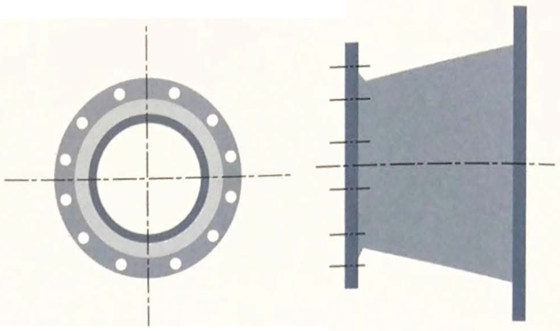
It should be noted that some quick connect/disconnect couplings (QC/DCs) require a specific presentation flange face. Spool pieces and reducers with compatible faces will only be used with the specific transfer arms for which they are required (see article “Equipment and cargo system of LNG onshore terminalsMarine loading arms (MLAs)“).
Isolating valves for cargo tanks must meet the requirements of the IGC Code. Where cargo tanks have a maximum allowable relief valve setting (MARVS) greater than 0,7 bar (Type C tanks), the principal liquid and vapour connections on the tank dome (except relief valve connections) will usually be fitted with a double valve arrangement. This will typically consist of one manually operated valve and a remotely operated isolation valve, fitted in series. For Type A and Type B cargo tanks (with a MARVS less than 0,7 bar) the IGC Code allows single shut-off valves for liquid and vapour connections. Under the IGC Code, these valves may be remotely actuated but must also be capable of local manual operation.
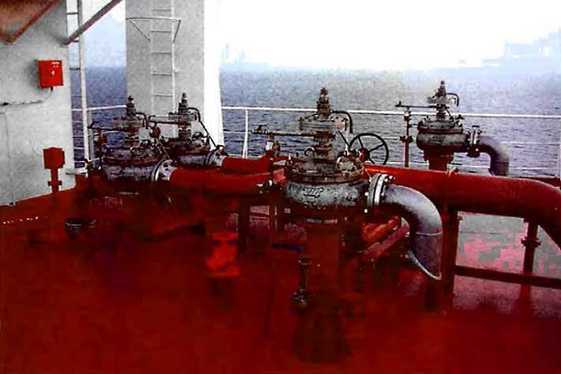
Remotely operated emergency shutdown (ESD) valves are provided at the liquid and vapour manifolds for all gas carriers.
The types of valve normally found on gas carriers are ball, globe, gate or butterfly valves. These valves are usually fitted with pneumatic or hydraulic actuators.
Ball valves for liquefied gas service may be provided with a means of internal pressure relief to overcome the phenomenon of “liquid lock“. Such valves are usually marked on the body with an “upstream” and “downstream” label, or an arrow cast into the body, to help ensure the valves are fitted the right way round. However, manifold valves (which are bi-directional) should generally (subject to any deviations of the design), if they are marked with a single arrow, have that arrow pointing outboard, or have the downstream side outboard. The presence of an indication mark does not, of itself, guarantee a satisfactory valve design.
System design will usually be such that valves will default to a safe position in the event of an actuator power failure.
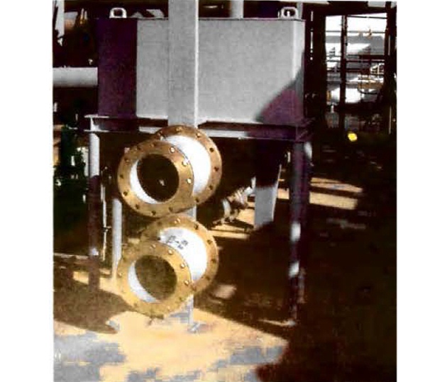
Cargo strainers
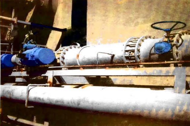
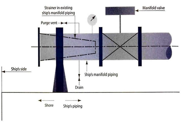
In the LNG trade, strainers are commonly provided at the manifold connections for loading and discharging. It is important not to bypass these strainers, which should be checked and cleaned when necessary. The strainers are installed to protect cargo handling equipment from damage by foreign objects and many are designed for one-way flow only.
Liquefied gas cargoes are highly refined products that are normally free from contaminants. However, strainers may be fitted at several places in the cargo system, such as at or near the cargo manifolds and in the reliquefaction system, to protect equipment from damage by any debris that has accidentally entered the cargo system and has not been removed by normal good operational practice and visual inspections.
In the early days of the LNG industry it was normal not to fit filters in ship systems. However, serious damage was caused to cargo pumps by nuts and bolts accidentally left inside a ship’s tank and some of these entered the shore system. As a result conical strainers were fitted into the manifolds. Alternatives, such as basket-type strainers in the main lines, are sometimes fitted to other types of gas carriers.
For LPG and similar cargoes, strainers have plates perforated with holes of about 3 to 5 mm diameter. Filtration standards are usually higher in the LNG industry, with typical mesh sizes of ASTM 20 (nominal aperture 0,84 mm) fitted for systems that have been proven to be clean, but a finer mesh may be used for the first two cargoes after a new terminal or ship enters service or undergoes maintenance. When using a finer mesh, head loss should be considered, as well as the fact that the pressure drop across the strainer may cause cooling through the Joule-Thomson effect, causing possible freezing of heavier hydrocarbons on the surface of the filter and resulting in blockages.

It is important that the filtration standard is appropriate as, if LNG strainers are used for LPG cargoes, the higher amount of moisture and debris in the LPG cargo causes frequent strainer blockage, even though the cargo itself is within normal purity standards. This is why LPG cargoes use coarser filters than the LNG trades.
Irrespective of the degree of filtration required, the strainer should not generally cause excessive pressure loss in service when clean, which is usually token as about 0,5 bar at full flow. If clogged, strainers should usually be able to withstand, without collapsing, a differential pressure of 3 bar during loading and the maximum pressure that can be generated by the ship’s pumps during unloading. The system will include pressure indicators upstream and downstream of the strainer to indicate possible blockage, as well as a suitable means to drain and purge the strainer assembly safely for maintenance and cleaning.
In vapour systems, strainers may be fitted to prevent rust or dust carry-over into compressors or similar machinery. These may use very fine mesh and are sometimes supplemented by even finer mesh cloth filters for commissioning. It is important to remove any such commissioning filters once a system has been proved to be clean and is in normal service.
Emergency shutdown (ESD) systems
The primary concept behind a linked ESD system is that the party receiving liquefied gas, ie the ship in the loading port and the shore in the discharge port, can shut down the transfer process in a safe and controlled manner and so remain in control of events at its location.
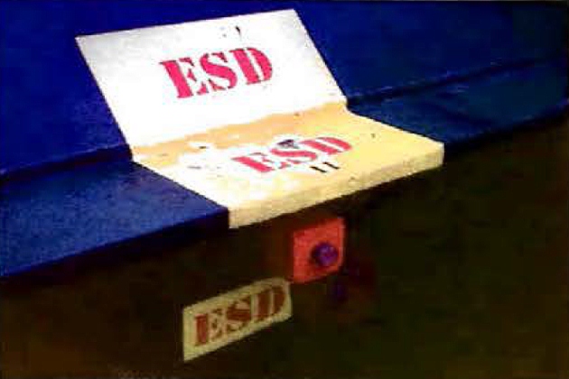
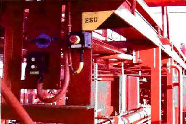
ESD push buttons or pneumatic valves are provided at a number of locations around the ship (bridge front, gangway, compressor room and cargo control room, emergency control station). When operated, these controls close remotely actuated valves and stop cargo pumps and compressors (where appropriate). This provides an emergency stop facility for cargo handling. Such emergency shutdown is also required to be automatic upon loss of electric control or valve actuator power. Furthermore, if a fire should occur at a tank dome or cargo manifold (where fusible plugs are situated) (see article “Sources of ignition on ships carrying LNG/LPGFire and Fire-Fighting Management“), the ESD system is automatically actuated. In some designs, the overfill alarm in an individual tank may activate ESD and close the ESD valves. In other designs, it is the individual tank filling valves that close automatically upon the actuation of an overfill sensor in the tank to which they are connected. Per the IGC Code, if this latter option is used, activation of the full ESD system should be initiated when the high level sensors in all tanks to be loaded have been activated. ESD valves may be either pneumatically or hydraulically operated but, in either case, they are intended to fail to a safe position, ie they are designed to close automatically upon loss of actuating power.
The functions of the cargo ESD are to stop cargo liquid and vapour flow in the event of an emergency and to bring the cargo handling system to a safe, static condition.
The IGC Code provides core requirements for an ESD system. These comprise manual trip points and automatic fire sensors that can initiate remote closure of ESD valves “for shutting down liquid and vapour cargo transfer between ship and shore” and require that this emergency trip, when activated, must also stop cargo pumps and compressors. However, these provisions may not necessarily provide adequate protection, particularly against overflow, during other operations involving the transfer of liquid and vapour onboard. It should be recognised that operations such as reliquefaction or cargo tank spraying may be routine operations at sea, where level alarms and shutdown may be inhibited for practical reasons.
The scope of the IGC Code effectively ends at the ship’s manifold and it has no mandate over the design of the terminal’s equipment. Linked systems are installed so that activation of an ESD trip on a ship will send an ESD signal to shore and vice versa. Although the Code requires cargo transfer procedures to be agreed and loading rates to be adjusted to limit surge pressures on valve closure, the impact of shipboard emergency shutdown on the shore is not considered.
The core requirement of the IGC Code is that an ESD shutdown is initiated by manual trips or by thermal devices. However, there may be valid reasons to supplement these core initiators with others to suit actual operating requirements. Similarly, in some cases additional shutdown actions may be necessary to stop liquid and vapour flow. As well as these ESD functions, the IGC Code requires trips that are designed to protect the ship and its cargo system against damage. These trips usually require cargo pumps and compressors to be stopped, and on many ships the actions are combined such that a trip due, for instance, to low tank pressure, will be activated via the ESD system or vice versa.
Suggested reading: Properties of liquefied gases
There are, therefore, differences between the core ESD trips defined by the IGC Code that are common to all gas carriers and those that may be in place on a particular gas carrier. Although this distinction may not be of great consequence when the ship is at sea, it could be important when considering cargo operations in port, particularly when the ship’s ESD system is linked to the terminal’s system (see article “Ship/shore interface for safe loading and unloading of LNG/LPGLinked Emergency Shutdown (ESD) Systems” and Tables “Ship/shore interface for safe loading and unloading of LNG/LPGEmergencies that may initiate the ESD” and “Ship/shore interface for safe loading and unloading of LNG/LPGActions that are usually initiated by the ESD“).
For the purposes of this publication the acronym ESD1 will be used when referring to the emergency shutdown of the transfer of cargo during loading or unloading. Depending on the context, the term may apply to an ESD1 trip signal, event or condition.
During transfer, stopping the flow requires the pumps and compressors or blowers to trip and, isolating the ship and shore from each other, requires the intervening valves to close.
The cargo transfer ESD process, at the majority of terminals where these systems are implemented, is divided into two stages:
ESD1
This shuts down the cargo transfer operation in a quick and controlled manner by stopping the transfer pumps and closing the shutdown valves and other relevant equipment in ship and shore systems.
ESD2
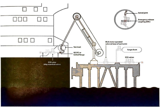
| Fig. 12 Initiation of ESD2 | Fig. 13 ESD2 closes ERS valves and uncouples MLAs | Fig. 14 MLAs disconnect and retract with minimum spillage |
|---|---|---|
 |  |  |
| Initiation of ESD2, immediately initiates an ESD1, shutting down the transfer operation on the LNGC and the terminal. (Note: The purpose of this signal is to guarantee transfer pumps are tripped before MLA release. Some terminals may have alternative arrangements to ensure safe release). | With the transfer pumps stopped, the ESD2: | Each MLA incorporates a powered emergency release coupling (ERC) to achieve disconnection with minimum spillage (dry-break concept). Many terminals will incorporate a surge relief system. For loading terminals, this may comprise a fast opening foil-safe dump valve that diverts liquid flow to a surge drum while the ERS and ESD valves are closing, minimising surge. |
| Closes emergency release system (ERS) valves on the MLAs within 5 to 10 seconds | ||
| uncouples the MLAs within 2 seconds of ERS valve closure. | ||
| (Note: ESD2 requires the provision of an ERS to disconnect the arms from the LNGC). | ||
The IGC Code requires all gas carriers to have an ESD system and so it must be recognised by terminals that the ship may shut down automatically, without prior warning, during cargo transfer operations. The terminal will need to understand the implications of this, particularly with respect to the generation of surge pressures in the transfer system.
It may be regarded as prudent for any LNG, LPG or chemical gas ship or terminal that does not have the ability to link its ESD system to shore or ship to be modified to make this possible.
There is a certain amount of overlap with the other safety systems covered by the IGC Code:
- ESD1;
- cargo tank overflow protection;
- cargo tank pressure protection;
- gas burning safety system.
Note that ESD1 does not necessarily include cargo tank vacuum protection. It may be prudent for consideration to be given to a limited number of additional ESD1 initiators.
It is a mandatory requirement of the IGC Code that gas carriers are provided with both high level alarms and overfill protection, each system independent of the other. The IGC Code provides that high level alarms must also be independent of other level indicators, although additional level alarms/trips being activated by the level gauging system is acceptable. In simple terms The IGC Code also requires the valve to be actuated “in such a manner that will prevent excessive liquid pressure in the loading line“.x, the overfill protection system closes a valve to prevent the tank becoming liquid-full. Although the IGC Code does not specify a particular level at which the high level alarm should operate, it is commonly set at a level that will warn the officer of the watch (OOW) well in advance of topping off.
A small number of overflows have occurred at the commencement of discharge and not during loading. This fact is commonly taken into account when designing the system so it provides protection against an overflow caused, for example, by internal transfer or a leaking valve. For instance, the high level signal can be used to trip the cargo pumps.
In addition to relief valves, pressure protection of the containment system is provided by a number of manual and automatic trips that shut down cargo machinery. In some gas carriers, particularly those without a ship/shore link, the functions of ESD1 and “cargo tank protection” are combined and this is the source of yet more confusion.
One item to consider is the effect of ESD1 on the boil-off gas (BOG) compressors on LNG carriers. The main practical advantage of separating the BOG compressor from the ESD system is that a route should generally always be available for the disposal of excess gas in the event of an ESD1, rather than causing the cargo tank relief valves to lift. This is of particular significance during loading, where the rate of cargo tank pressure rise can be particularly rapid.
Caution should be taken when considering the addition of further initiators to ESD1, as well as any service modifications to software, such as may be undertaken when the ship is on trials. Any proposals should be subject to rigorous assessment, possibly including a failure mode and effects analysis (FMEA), and should be fully documented.
Effect of surge pressure should FSD activate
A vital consideration, particularly during loading, is the possibility of surge pressure generation (see article “Equipment and cargo system of LNG onshore terminalsPipelines and valves – engineering standards and surge pressure“) when the ship’s ESD system is actuated. The situation varies from terminal to terminal and is a function of the loading rate, the length of the terminal pipeline, the rate of valve closure and the valve characteristic itself. The phenomenon of surge pressure generation is complex and its effects, such as the rupture of hoses or hard arm joints, can be extreme. Precautions are, therefore, necessary to avoid damage and sometimes loading jetties are fitted with surge pressure drums (see article “Equipment and cargo system of LNG onshore terminalsPipelines and valves – engineering standards and surge pressure“).
Terminals should, for example, confirm the ship’s ESD valve closure times and adjust loading rates accordingly, or place on board a means to allow the ship to actuate the terminal ESD system to halt the flow of cargo before the ship’s ESD valves start to close. On LNG carriers the ship and shore ESD systems are normally connected, ensuring that both systems shut down in an appropriate manner when an ESD is activated. Consultation between the ship and shore will always take place to establish the parameters relevant to surge pressure generation and to agree a safe loading rate (see also article “Ship/shore interface for safe loading and unloading of LNG/LPGDiscussions Prior to Cargo Transfer“). A detailed discussion of surge can be found in SIGTTO’s “Guidelines for the Alleviation of Excessive Surge Pressures on ESD” (Reference 2.17).
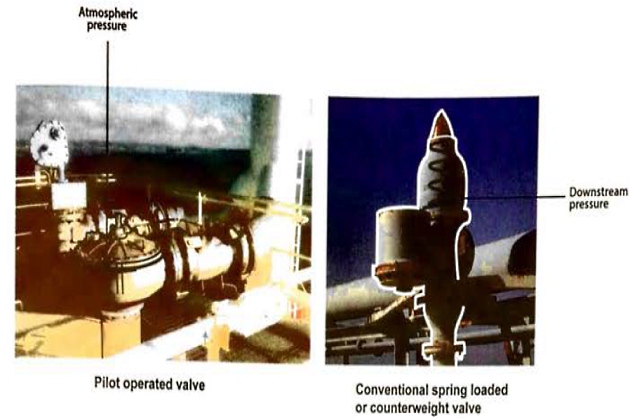
Relief valves for cargo tanks and pipelines
The types of valves normally fitted are either spring loaded or pilot operated. Pilot operated relief valves may be found on all tank types, while spring loaded relief valves are usually only used on Type C tanks. The use of pilot operated relief valves on fully-refrigerated tanks helps to ensure accurate operation at the low pressure conditions prevailing. Their use on Type C tanks allows variable relief settings to be achieved using the same valve, which may be done by changing the pilot spring. Figure 16 shows a typical pilot operated relief valve. Other types of pilot valve are available for adjustment of set pressure and blowdown pressure.

Type C tanks on recent liquefied gas carriers, which fall under the American Society of Mechanical Engineers (ASME) Pressure Vessel Code Div II (Reference 2.18), may only require one MARVS setting as these more recent ASME requirements align with the IGC Code requirements. The original ASME regulations impose more stringent safety factors for pressure vessel design than the IGC Code requirements.
Whenever such valves are used for more than one pressure setting, it is common for a proper record to be kept of changes to the pilot valve springs. The pilot assembly cap will always be resealed after such changes, which helps to ensure that no unauthorised adjustments can be made. When relief valve settings are changed the high pressure alarm will usually be adjusted. Generally, the valve needs will be tagged to show the set pressure on the fitted valve, both in the cargo control room and on the valve itself. Commonly, auxiliary setting devices used for changing the pressure settings will be connected to the same valve, as they are calibrated to be so. Proper records to this effect should be maintained onboard.
Pressure relief valves on tanks require routine maintenance and, for further information on this subject, you may wish to consult SIGTTO publication, “An Introduction to the Design and Maintenance of Cargo System Pressure Relief Valves on Board Gas Carriers” (Reference 2.19).
The IGC Code requires all pipelines that may be isolated, when full of liquid, to be provided with relief valves to allow for thermal expansion of the liquid. These valves usually relieve to the cargo tanks. Alternatively, the exhaust may be taken to a vent riser via liquid collecting pots, in which case, under the terms of the IGC Code, a means for detecting and disposing of liquid in the vent system must be provided.
Types of pressure relief valves
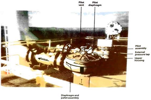
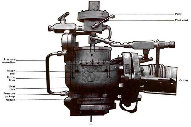
Pilot operated pressure relief valves (Figures 18, 19 and 20)
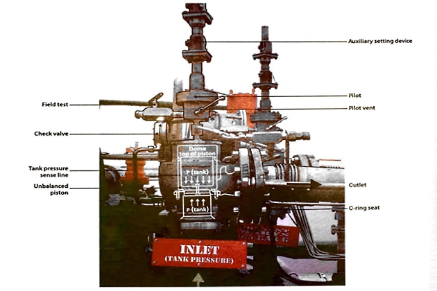
A pilot operated pressure relief valve consists of a main valve and a pilot valve. The main valve has an unbalanced piston or diaphragm. Tank pressure is applied to the top of the piston or diaphragm via the pilot. As the area at the top of the piston or diaphragm is larger than the bottom, the valve remains closed. When the set pressure is reached the pilot valve opens, venting the space above the piston to atmosphere or the vent stack.
The imbalance of the piston usually ranges from 1.5:1 to 3:1. This means that the area on the top side of the piston is larger than the seating area.
For example, with a 2:1 imbalance, the area of the top side is two times that of the seating area. If the set pressure is 7 bar and the seat area is 12 cm2, then the net forces holding the seat closed, immediately prior to opening, is 84 kg.
- Upward force = 12 cm2 · 7 kg/cm2 = 84 kg;
- Downward force = 2 (12 cm2 · 7 kg/cm2) = 168 kg;
- Therefore, net force holding valve shut = 168 – 84 = 84 kg.
For the valve to open in this example, the pilot valve will depressurise the cavity on the top side of the piston to a pressure equal to 50 % of the inlet pressure. When that occurs the forces are in balance and the valve is on the threshold of opening. The piston will then move upwards and the pressure will remain constant during this period. When the pilot closes the top cavity is re-pressurised and the piston closes.
Spring operated pressure relief valves
The piston or valve seating is accomplished through the pressure exerted by a coil spring onto the top of the piston or valve. As the tank pressure increases the valve seating contact force is reduced, making the setting of an exact set pressure more difficult to accomplish. This is particularly true at
low pressures.
The opening of the valve and the amount of opening depends, therefore, on the compression of the spring. Any back pressure downstream of the pressure relief valve, will also tend to close the valve.
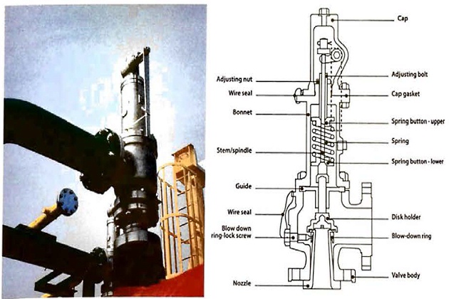
The operation of the valve and its maintenance is simpler than for the alternative pilot valve type, but it has the disadvantage that, in general, it cannot be set as accurately, particularly at low pressures.
The different characteristics of the pilot operated and conventional spring loaded pressure relief valves are shown in Figure 22.
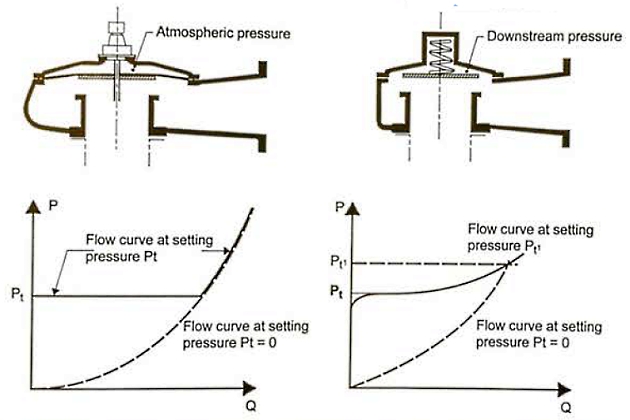
As the force holding the valve to its seat becomes zero at the pre-set opening pressure, the pilot operated valve lifts completely under the thrust exerted by the gas. However, the spring loaded valve can be raised only by a further increase in pressure since the compression of the spring requires an additional force, to which the static pressure due to the flow downstream of the valve will need to be added.
Cargo Pumps
Cargo pumps fitted on board refrigerated gas carriers are normally of centrifugal design and may be either of the deepwell or submerged pump type. They may operate alone or in parallel with one another. They may also operate in series with a deck mounted booster pump and a cargo heater, which would be required during discharge of LPG to pressurised storage.
Some fully-pressurised ships discharge cargo by pressurising tanks, with vapour and booster pumps fitted to speed the cargo transfer.
Pump performance curves
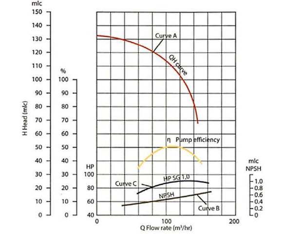
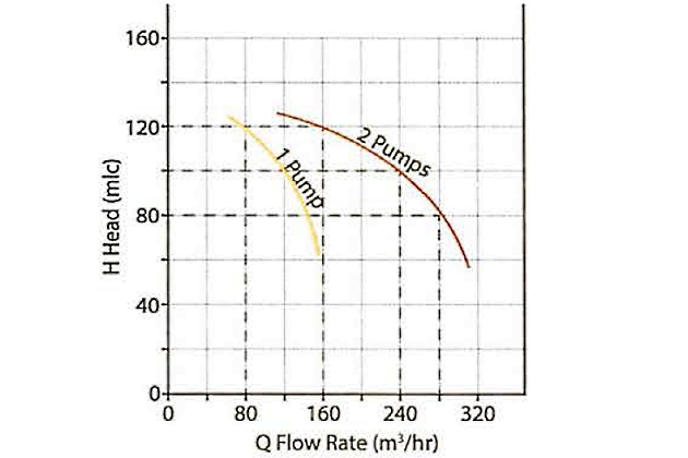
An understanding of pump performance is important when considering the work done by cargo pumps. Figure 24 shows a typical set of performance curves for a multi-stage deepwell pump (see also Figures 24 and 25).
The flow-head curve
Curve A shows the pump capacity, in flow rate (m3/hr), as a function of the head developed by the pump, given in terms of metres liquid column (mlc).
This curve is called the pump characteristic. By adopting mlc and flow as the main criteria, the pump characteristic is the same whatever fluid is pumped. Taking curve A, the pump will deliver 100 m3/hr against a head difference of 115 mlc between the ship and shore tanks. To convert this head into pressure the specific gravity of the cargo being pumped will need to be known.
For example, at a head of 105 mlc, the increase in pressure across the pump when pumping ammonia at minus 33 °C (-33 °C) with a specific gravity of 0,68 would be:
(Note: factor 10,2 denotes the height, in metres, of a water column maintained solely by atmospheric pressure. See Table Properties of liquefied gases“Physical properties of gases”).
The net positive suction head curve
Curve B shows the net positive suction head (NPSH) requirement for the pump as a function of flow rate. The NPSH requirement at any flow rate is the positive head of fluid required at the pump suction, over and above the cargo’s vapour pressure, to prevent cavitation at the impeller. For example, at a capacity of 100 m3/hr the NPSH requirement for the pump is 0,5 mlc. This means that with a flow rate of 100 m3/hr, a minimum head of cargo equivalent to 0,5 metres is required at the pump suction to prevent cavitation. An over-pressure of 30 mbar in the cargo tank is equivalent to 0,5 metres head when pumping ammonia at minus 33 °C (-33 °C).
Read also: Gas laws, thermodynamic principles and reliquefaction
NPSH considerations are particularly significant when pumping liquefied gases because the fluid being pumped is always at its boiling point. It should be remembered that if cavitation is allowed to occur within a pump, not only will damage occur to the impeller but the shaft bearings themselves will be starved of cargo. This will restrict cooling and lubrication at the bearings and damage will quickly result.
The power consumption curve
Curve C shows the power absorbed as a function of pump capacity. This curve is normally given for a specific liquid density and can be converted for any liquid by multiplying by the ratio of specific gravities.
Running pumps in parallel and in series
During a gas carrier discharge, cargo pumps are usually run in parallel, but when a refrigerated ship discharges to pressurised storage, cargo tank pumps are run in series with a booster pump (see article “Features of cargo delivery LNG/LPG carriersDischarge via booster pump and cargo heater“).
When pumps are run in parallel, their individual pump characteristics can be combined to give a flow/head curve for 2, 3 or 4 pumps when running together. Taking the pump characteristic shown in Figure 24, the flow/head curve for running two pumps in parallel can be easily plotted by approximately doubling the flow rate at the appropriate head for a single pump. This is shown in Figure 25. Similarly, when running three pumps in parallel, the flow rate at the appropriate head can be obtained by multiplying the single pump flow rate, at the same head, by three. Therefore, a series of curves can be built up from the pump characteristic curve of a single pump.
When pumps are run in series the individual pump characteristics curves can again be combined to give the appropriate curve for the series configuration. Figure 26 shows how this can be done using, for example, two similar pumps in series. This time, for each value of flow rate, the appropriate head developed by a single pump is doubled to give the resultant head.
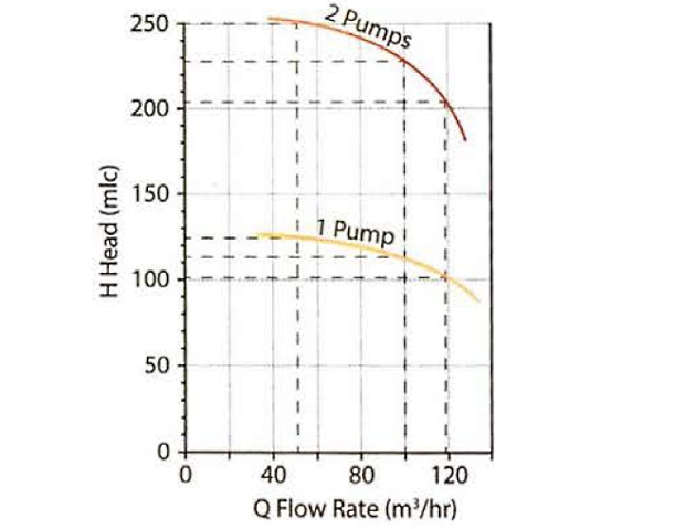
The cargo flow rates achieved by any pump, or combination of pumps, will depend on the back pressure encountered due to static head (difference in liquid levels of receiving tank and tank being discharged) and the resistance to flow in the pipeline. To determine the flow rate for a particular pipeline setup, the shore pipeline flow characteristic will be superimposed upon the ship’s pumping characteristic. This is dealt with in article “Features of cargo delivery LNG/LPG carriersDischarge by cargo pump” but it should be noted that the system resistance may be steep enough to restrict the flow shown in Figures 25 and 26.
The minimum necessary pumping power should usually be used to reduce heat input to the cargo and limit the rise in saturated vapour pressure (SVP) of the delivered cargo.
Deepwell pumps
Deepwell pumps are the most common type of cargo pump for LPG carriers. Figure 27 shows a typical deepwell pump assembly. The pump is driven either electrically or hydraulically (through a sealing arrangement) by a motor that is mounted outside the tank. The drive shaft is held in carbon bearings inside the cargo discharge tube and the bearings are lubricated and cooled by the cargo flow.
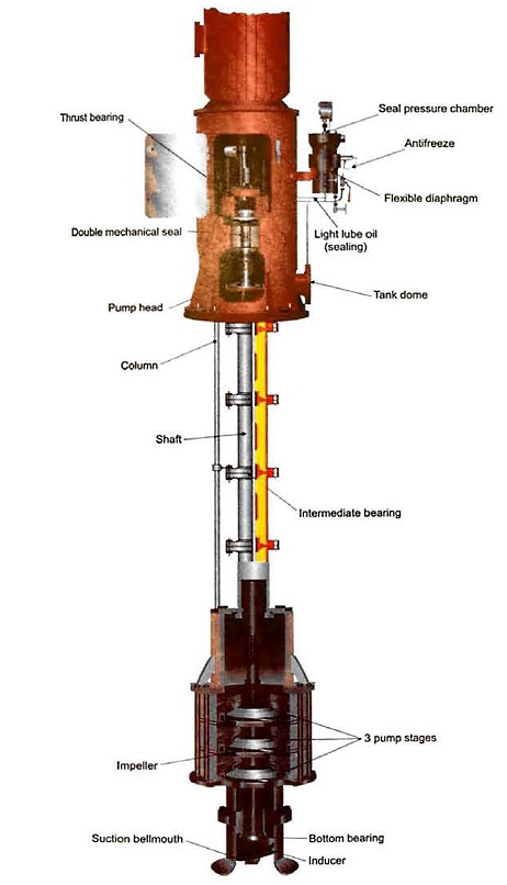
The centrifugal impeller is mounted at the bottom of the cargo tank and frequently comprises two or three stages together with a first stage inducer. The inducer is used to minimise the NPSH requirement of the pump. Pump shaft sealing at the cargo tank dome consists of a double mechanical seal flushed with lubricating oil. This stops cargo leakages to atmosphere. The accurate alignment of the motor coupling, thrust bearing and mechanical oil seal is important.
On larger gas carriers the length of the drive shaft can be a problem as the longer it becomes, the more support is needed. Therefore, larger gas carriers (including most LNG carriers) are usually fitted with submerged pumps.
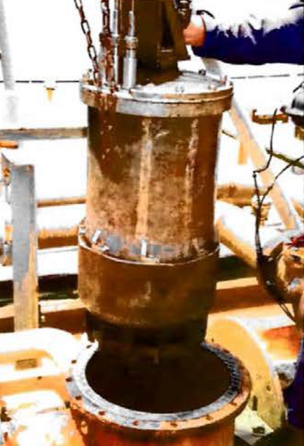
Submerged motor pump
Submerged motor pumps are installed at the bottom of cargo tanks and enable very low pump-down levels to be achieved.
The pump and electric motor are integrally mounted on the same shaft, which eliminates the need for a mechanical seal or coupling. Power is supplied to the motor through specially sheathed cables. Electrical cabling is passed through a hazardous area junction box in the tank dome and then, by flexible stainless steel armoured insulated power cables, to the motor terminals.
The pumps are cooled and lubricated by cargo flow and are prone to damage due to loss of flow. Therefore, the pump is protected from dry running by safety devices such as an under-current relay, a low discharge pressure switch or a low tank level switch. Figure 29 shows a typical submerged pump/motor assembly for an LNG carrier.
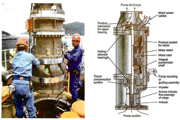
The electric drive motors of submerged pumps are not “certified safe” – so it is prudent to ensure there is always some cargo liquid level and a positive pressure in the tank during operation to avoid any risk of flammable atmospheres developing. For the same reason, it is prudent to isolate submerged cargo pump motors from the electric supply. This isolation capability is a requirement of the IGC Code.
Submerged pumps need to be designed for the particular grades of cargo found on the ship’s Certificate of Fitness. For example, ammonia is an electric conductor and can also be a particularly corrosive cargo to materials such as copper wires and to electrical insulation. Pump design should usually take this into account. To preserve the electric motor, pumps used for ammonia have the electric stator enclosed in a “can“.
Booster pumps
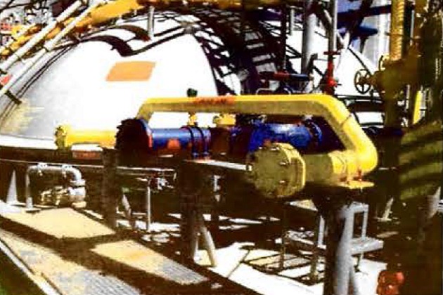
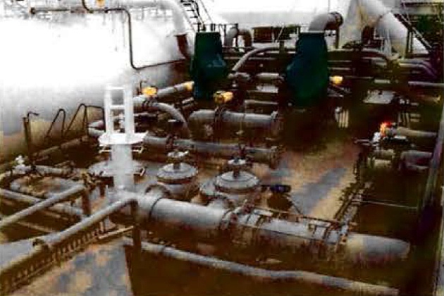
Booster pumps are usually of the centrifugal type. They may be vertically or horizontally mounted on deck in the appropriate discharge line. In these positions they will be driven by an “increased safety” (E Exe) (see article “Liquefied Petroleum Gas Reliquefaction Plant and Boil-Off ControlElectrical Equipment“) electric motor. Although uncommon, they may also be installed in the cargo compressor room, as such an arrangement requires consideration be given to the consequences in the unlikely event of a high pressure liquid leak occurring from the pump. When fitted in the compressor room they are driven through a gas-tight bulkhead by an electric motor installed in the electric motor room. Figures 31 and 32 show examples of these types of pump.
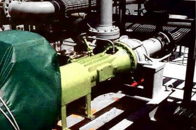
The particular pumps shown are fitted with double mechanical seals.
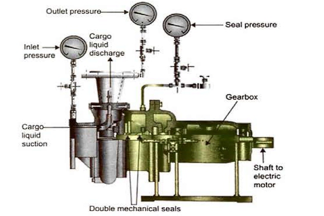
The seal flushing system, for example, should be well maintained to ensure continuing reliability.
Ice prevention at cargo pumps
The formation of ice or hydrates (see article Properties of liquefied gases“Reaction with water – hydrate formation”) may occur in ships carrying refrigerated or semi-pressurised LPG. Hydrates may also be transferred from the terminal during loading operations. Hydrates from the shore can be removed by cargo strainers in the terminal loading lines (see point
“Cargo strainers” above).
Hydrate formations may enter cargo pumps, block lubricating passages, unbalance impellers and seize bearings. To prevent such damage it is common practice to inject a small quantity of freezing-point depressant into the cargo pump, particularly submerged pumps, to facilitate de-icing. Because of the danger of methanol contamination to certain LPG cargoes, injection of this product will not normally be allowed without the cargo receiver’s agreement. In the event of cargo pumps becoming iced up, on fully-refrigerated ships it is not possible to discharge, but on semi-refrigerated or pressurised gas carriers, discharge can be completed by pressurising the cargo tanks.
Unlike conventional oil tankers, cargo pumps on gas carriers are designed to operate satisfactorily regardless of the setting of the discharge valve. Recirculating product back to the tank to control cargo discharge rate is not usually desirable as unnecessary recirculation adds heat to the system while increasing the risk of tank overfill.
Emergency cargo pump
Emergency cargo pumps are usually found on vessels that are fitted with submerged cargo pumps where other means of removing cargo from a tank, in the event of total pump failure, are not available.
An emergency cargo pump is typically only fitted on membrane ships, although some LPG very large gas carriers (VLGCs) of Type A tank design may also be outiftted with an emergency cargo pump.
Each membrane ship carries an emergency cargo pump that can be used in the event of failure of either one or both cargo pumps in a particular tank. The cargo tanks are equipped with an emergency pump well. This pump well has a foot valve that is held closed by highly loaded springs. The emergency pump is lowered down the well after purging the well with nitrogen (N2). The weight of the pump overcomes the compression of the springs to open the foot valve. It is prudent to maintain a small flow of N2 while the pump is being installed.
It is standard practice to reduce and maintain cargo tank pressure to near atmospheric pressure throughout the installation/fitting.
When not in use, the emergency pump is stowed in a special case (coffin) that has connections to introduce N2. This ensures that the pump can be kept in a “dry” atmosphere prior to use.
Some LPG carriers have permanently installed emergency pumps; others employ a well and foot valve system similar to membrane ships.
Full instructions for fitting and operating the emergency pump will be found in the ship’s cargo operations manual.

Some gas carriers, notably fully-refrigerated and semi-refrigerated LPG carriers, are fitted with one or more deck tanks. These small Type C tanks are primarily used when changing grades or can be used when discharging. When changing grades, they can be used to collect residual cargo amounts (see article “Preparation of loading and unloading operations for LNG/LPG carriersDisplacement“) or, if carrying a quantity of compatible cargo, can be used for the purposes of gassing up (see article “Preparation of loading and unloading operations for LNG/LPG carriersGassing-up at sea using liquid from tanks“). They can also be used for collecting cargo via pressurised discharge (see article “Features of cargo delivery LNG/LPG carriersDischarge by pressurising the vapour space“).
Design requirements (ie relief valve systems) and application limits (ie use of deck tanks not being permitted for the carriage of certain cargoes) can be found in the IGC Code. Deck tanks are usually listed as cargo tanks on the Certificate of Fitness.
It is prudent to ensure that the design limits of deck tanks are clear to the operators. For example, deck tanks sometimes have a different minimum temperature limit compared to the cargo tanks, especially on ethylene carriers. Deck tanks may be connected to the reliquefaction system – in which case they can be loaded to similar filling limits compared to the cargo tanks. Otherwise, it is necessary to compensate for the maximum temperature the deck tank contents may reach during service to avoid hydraulically-full conditions arising. The inhibitor content, ascertained from the Certificate, needs to be maintained at sufficient levels at all times for inhibited cargoes, such as butadiene or VCM, stored in the deck tank.
Cargo Heaters
Ordinarily, refrigerated cargo will need to be heated before it can be transferred into pressurised storage systems, to avoid low temperature embrittlement of the cargo tanks and pipelines.
Heating can take place while loading a cold cargo into a pressurised ship or when discharging a refrigerated cargo into pressurised tanks ashore (see article “Features of cargo delivery LNG/LPG carriersDischarge via booster pump and cargo heater“).
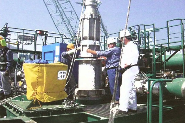
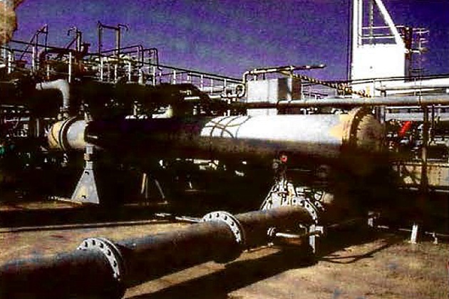
Direct cargo heaters
A cargo heater is usually a conventional horizontal shell and tube type exchanger and is normally mounted in the open air on the ship’s deck. The cargo passes through one side of the tubes while the seawater flows on the other side before going overboard. They are known as “direct” heaters.
The heaters are typically designed to raise the temperature of fully-refrigerated propane from minus 42 °C (-42 °C), or ammonia from minus 33 °C (-33 °C), to the outlet temperature required. However, it should be noted that the cargo flow rate at which this temperature rise may be achieved is based on an assumption about the seawater inlet temperature, which may be 15 °C or higher. The capacity of any direct cargo heater will be reduced significantly if the inlet water temperature is below the figure assumed and, under such circumstances, only very slow discharge rates may be possible. It should also be noted that the capacity of any direct cargo heater will be affected by the specific heat of the cargo being carried. For instance, the amount of heat required to raise the temperature of 1 kg of ammonia by 1 °C is significantly higher than that required for propane so the amount of fully-refrigerated ammonia that can be heated is lower than the amount of propane under similar conditions.
Suggested reading: Overview of the Carriage of Liquefied Gases by Sea
The manual supplied with the cargo heater may not contain sufficient data for the Master to estimate discharge rates for conditions not specified in the performance curves. Expert advice should be sought if it is proposed to use the heater outside the conditions specified by the manufacturers.
Figure 37 shows a simplified heater arrangement. There is a requirement for temperature controls and alarms to ovoid freezing as this is a risk that always hos to be guarded against.
Consideration should also be given when the heater is used in river berths, where the water is “fresh” (which freezes at about 0 °C) rather than “salt” (which freezes at about minus 2 °C (-2 °C)).
Before start-up, it is prudent to test both cargo and water sides for leakage and test water flow shutdowns as well.
Specific instructions will, ordinarily, be available onboard to cover the testing, operation and maintenance of the particular heater installed. They will, amongst other things:
- Identify the various alarms fitted to protect the unit;
- indicate how to test these alarms before use;
- provide correct start-up sequence and procedures;
- explain how to regulate cargo flow during operations;
- state how to shut down the heater correctly ofter use.
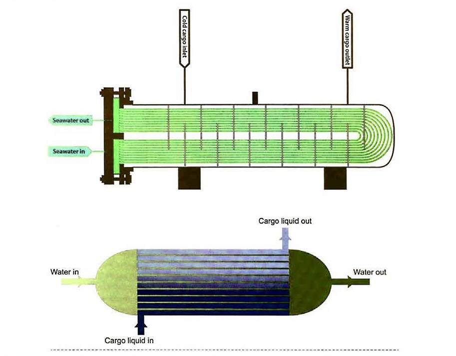
Indirect cargo heaters
Indirect cargo heaters use an intermediate circuit between the cargo and the heat source. Examples include a steam heated glycol system, where a glycol tank is heated by steam and the warm glycol is passed through the cargo heater and returned to the glycol tank to be reheated and recirculated.
Another type of alternative “indirect” heater is shown in Figure 38. In this case, an intermediate fluid in the lower heat exchanger (shown in dark blue) is evaporated by the seawater (shown in green) and condenses against the cold tubes in the upper exchanger, which have cold liquid cargo passing inside them.
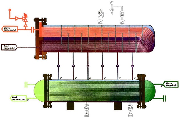
The intermediate fluid may be a refrigerant gas with a suitable evaporation paint or the cargo itself.
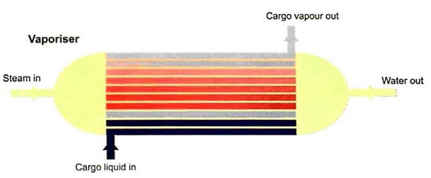
Cargo Vaporisers
A means of producing cargo vapour from liquid is often required on gas carriers. For example, vapour may be needed to gas-up cargo tanks after they have been gas-freed or to maintain cargo tank pressure during discharge if no vapour return line is provided from the shore. On LNG carriers there is also a requirement to occasionally produce vapour to supplement BOG to provide sufficient for use in the propulsion system.
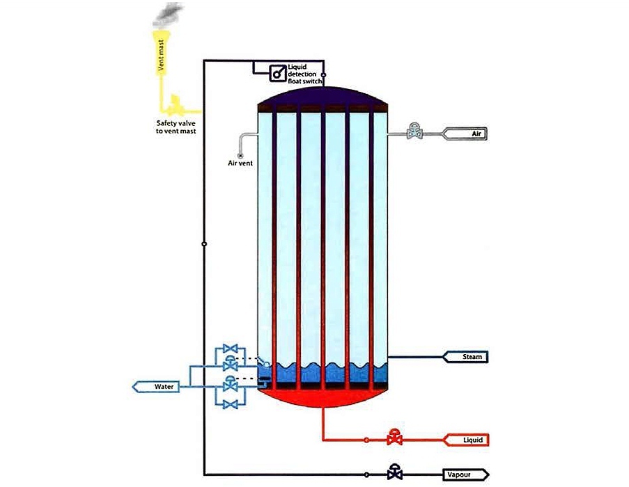
LPG carriers usually only have a single vaporiser, while on LNG carriers it is common practice for two vaporisers to be installed, one high duty (large capacity) for use when gassing up the LNG carrier and another low duty (low capacity) unit for use in maintaining the vapour supply to the engine room.
Cargo vaporisers may be vertical or horizontal shell and tube heat exchangers. They are used with either steam or seawater as the heating source and so are similar in construction to the cargo heaters described in point “Indirect cargo heaters” below. The main difference in the design is that a heater simply warms the liquid cargo, while a vaporiser is intended to change the phase of the cargo from a liquid to a apour.
If seawater is the heating medium in the vaporiser, care may need to be taken to prevent freezing and subsequent bursting of tubes if, for example, the cargo vapour pressure inside the vaporiser becomes too low.
- Butanes and other C4 cargoes: approx. 0,5 bar;
- VCM: approx. 1,1 bar;
- Ammonia or propone: approx. 4,5 bar;
- Propylene: approx. 5,8 bar.
As a general principle, the heating medium is started first and the cold liquid introduced very carefully until the pressure in the unit has reached the required value and the liquid level is correct. At this stage the outlet valve can be opened to supply vapour to the system and adjusted to ensure that pressure is maintained such that the liquid level in the vaporiser is adequate.
Regasification Units
A number of LNG carriers are fitted with the capabilities to regasify the LNG cargo and supply it directly into the high pressure shore gas grid, avoiding the need for a shore terminal to be constructed. To regasify the cargo a large heating system is needed because of the relatively high capacity throughput required to service the shore grid (see article “Offshore terminal for transshipment of liquefied gasTopsides production facility (regas specific)“).
Closed loop with steam heating
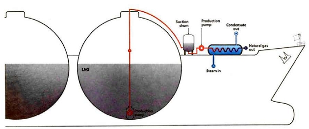
- LNG is directly heated by steam;
- generally suitable in areas with low seawater temperatures or environmental restrictions.
Combined open/closed loop with seawater and steam heaiing
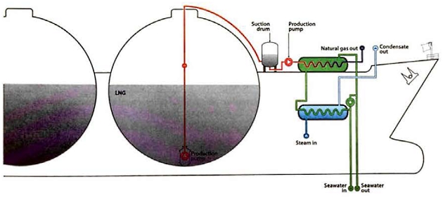
- LNG is directly heated by seawater;
- at low seawater temperatures the seawater is preheated in a steam heater.
Closed loop with steam heating and intermediate water/g lycol loop
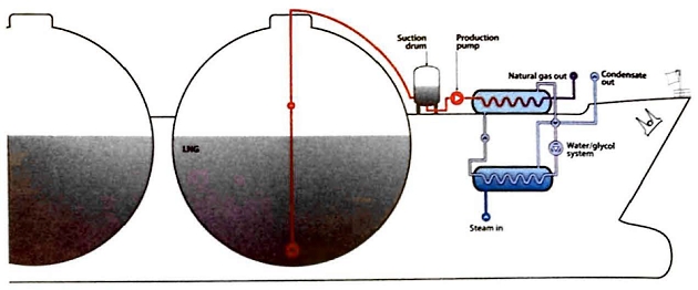
- LNG is heated against water/glycol;
- generally suitable in areas with low seawater temperatures or environmental restrictions.
Open loop with seawater heating and intermediate propane loop
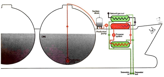
- LNG is heated against on intermediate loop with propane and then against seawater.
Did you find mistake? Highlight and press CTRL+Enter