As demand for LNG continues to grow and the value of natural gas remains high in the major consuming markets, the impetus to monetize offshore gas resources also grows.
- FPSO
- Topside layout
- Technical challenges
- Design challenges
- Geopolitical challenges
- Offshore LNG regasification
- Submerged buoy systems
- Offshore regasification safety
- Floating storage and regasification units (FSRU)
- Gravity-based offshore regasification units
- Heating value control in offshore LNG regasification plants
The potential to unlock offshore gas reserves without investment in capital-intensive pipeline infrastructure, infield platforms, and onshore infrastructure, while minimizing exposure to geopolitical and security risks, makes floating LNG production, storage, and offloading (LNG FPSO and FLNG) concepts worthy of close scrutiny (Barclay and Yang, 2006).
Also the restrictions of more stringent no-flaring rules being applied around the world are likely to prompt some existing offshore producers to aggregate gas from several fields and develop large-scale floating liquefaction (>4 MTPA capacity) as an alternative to the costly gas reinjection facilities or long-distance export pipeline. Building an offshore facility requires adapting current technology to an offshore environment, which could be costly and may present a safety risk. But as FLNG technologies on liquefaction and ship-to-ship transfer are being developed and proven, there is increasing confidence that FLNG is a viable option. Although no FLNG facilities currently exist (as of this writing), a facility is under development by Shell for the Prelude offshore gas field in Australia. Once this first unit is operational, it will open up new business opportunities for countries looking to develop their gas resources, bringing more natural gas to market. Shell is the first to go ahead with such a project, Prelude FLNG.
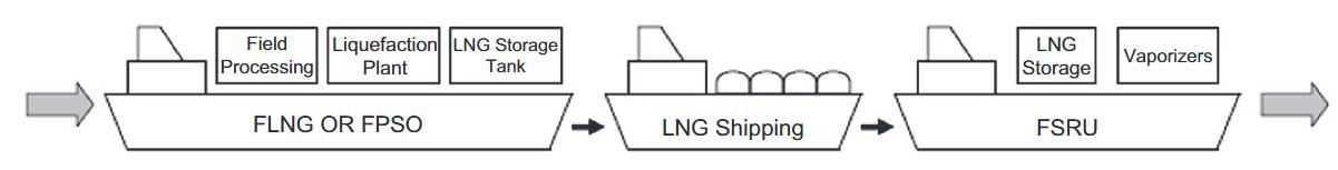
In contrast to the traditional LNG value chains, the offshore LNG value chain will consist of:
- an offshore production facility;
- floating offshore gas treating and liquefaction facility (FLNG or FPSO);
- the LNG loading facilities;
- LNG cargoes transport;
- the LNG unloading facilities;
- storage and regasification facility on the FSRU or regasification ship;
- and finally, tied into a gas distribution pipeline network (see Picture 1).
FPSO
A typical LNG FPSO design bases the installation on an LNG carrier hull. The various parts of the process are then located topside and distributed as modules that are installed on the deck. Depending on the intended capacity of the LNG FPSO and the need for treatment of the feed gas composition, the topsides typically may weigh from 20 000 tonnes to 50 000 tonnes for medium-size units producing 1,5 to 3 MTPA. For very large scale production units (3–5 MTPA) the topside weight may reach 70 000 tonnes or more.
The storage capacity of the FPSO will be related to the processing capacity, the intended offload schedule, and the need to store condensate and LPG, which is dependent on the feed gas composition. Current designs for medium-size units are being proposed with an LNG storage capacity of 180 000 to 190 000 m3 and LPG and LPG storage capacities of approximately 25 000 m3 each. For the very large scale units LNG storage capacity of 220 000 m3 has been proposed together with LPG and Condensate storage in the range of 100 000 m3 each.
Operating an LNG plant under an offshore setting presents a demanding set of challenges. In terms of the design and construction of the FLNG facility, every element of a conventional LNG facility needs to fit into an area less than one quarter the size of a land base terminal, while maintaining the utmost levels of safety and the flexibility required by LNG production.
The LNG containment systems need to be capable of withstanding the stress that can occur when the sea’s wave and current motions cause sloshing in the partly filled tanks. Product transfers have to consider the effects of winds, waves, and currents in the open seas.
Many solutions to reduce the effect of motion and weather are being developed. They are based on adapting current technologies for offshore oil and gas production to LNG production. Notably, the main difference is the cryogenic and volatile nature of LNG and the cargo transfer (ship to ship) operation is recognized as the critical link in the LNG chain (Mokhatab and Wood, 2007b; Mokhatabet al., 2008; Wood and Mokhatab, 2008b).
Topside layout
Layout criteria for an FPSO are more stringent than onshore due to the limited footprint, the need for good weight distribution, and the need for personnel refuge and escape routes (Finn, 2008). Safety isthe prime consideration for the layout of LNG FPSO. The primary safety concern is the inventory of hazardous, flammable gas, and the consequence of any loss of containment.
A major contributor to safe design is to ensure that initial arrangement and layout are aimed at arriving at a design that meets operational requirements and also will be compliant with regulations.Typically the following principles should be taken into consideration (DNV, March 2011):
- Segregation of accommodation and main working areas from the hydrocarbon processing areas.
- Provision of adequate and redundant access and escape ways from normally manned areas.
- Ensuring rational flow within the gas and LNG processing system.
- Maintenance of availability of Questions and answers to CES CBT test for seafarers about LRM Harding FFlifeboats.
- Provision of sufficient access for maintenance and repair and replacement offshore (e.g., LNG pumps).
- Permitting the installation and interconnection of modularized units.
- Limiting the amount and areal extent of hydrocarbon and cryogenic spills.
- Efficient installation of High Voltage cabling.
- Limiting congestion and permitting ventilation to reduce explosion potential and effect.
- Location of motion sensitive equipment in areas of least motion (e.g., at centerline).
- Orientation of equipment to minimize damage after failure or minimize hull-deflection effects.
- Minimizing or protecting against flare radiation.
- Optimizing sizing of fire-fighting demand by fire zone design.
- Optimizing vent and blowdown capacity by segregation.
- Limiting escalation after fire or explosion by separation distance or physical barriers (fire and blast divisions and deck coamings).
- Ensuring survivability of safety systems following an accidental event (e.g., redundancy and location of power systems, means of evacuation).
- Location of a turret with respect to safety and thrusters demand.
- Meeting material handling demands.
For example, Picture 2 shows a typical LNG FPSO layout by CB&I, which has considered the following aspects in terms of safety:
Living quarters, control room, and air intakes are located at the bow, upwind of any potential gas release.
- Power generation with air intakes and exhaust are located away from the NGL and LNG units.
- The internal turret is located forward to provide natural weathervaning capability.
- Utility systems are located just beyond the turret, which helps to maximize the distance between the hydrocarbon source and the living quarters.
- The NGL and LNG plants are located at the stern, providing maximum separation between the living quarters and hydrocarbons.
In terms of storage and transfer, the LPG units will present fewer problems than equivalent LNG installations. However, process plant for LPG production, typically involving tall fractionation columns (deethanizer, debutanizer, and depropanizer), will present some design challenges with regard to accommodating them structurally and reducing their sensitivity to motion.

LPG will potentially cause more severe fire or explosion if an accident occurs during offloading.These will need to be quantified in a safety study. In addition dispersion and detection of any leakages will need to consider the actual properties of the LPG, being higher in molecular weight than methane.
Shell FLNG
Picture 3 shows a rendering of the Shell LNG FPSO design for Northwest Australia. Shell is using its Floating Liquefied Natural Gas (FLNG) technology to develop its Prelude and Concerto gas discoveries, located in the Browse Basin off the northwest coast of Western Australia.
The design is being jointly developed by the Technip-Samsung Heavy Industries consortium. The design is planned for other FLNG facilities.
The FLNG vessel will be the world’s largest facility afloat when delivered in 2014. It is estimated to be 480 m long and 75 m wide and with 600 000 dwt (Sea Breezes Magazine, December 2009 Issue).
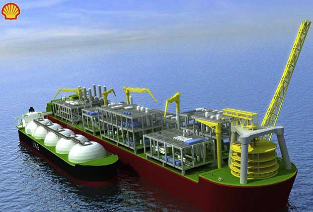
The 480 m-long floater, being built at the Samsung Heavy Industries shipyard in Geoje, Korea, will produce an estimated 3,6 MTPA of LNG, 1,3 MTPA of condensate and 0,4 MTPA of LPG from the Browse Basin WA-371-P permit, in 280 m water depths offshore Western Australia (McCulley, 2011).
Technical challenges
FPSO vessels have been used to produce oil and gas from deep-water fields since the 1970s, and the industries have proven design and operating experience. Using the same model, the FLNG vessels arecustom built to meet the safety requirements of natural gas liquefaction.
The facility has to adapt to the gas field’s unique characteristics, mainly:
- the gas reservoir capacity;
- the gas compositions;
- acid gas contents;
- and the local metocean conditions (waves, wind, etc.).
Project economic criteria of offshore plants are different than onshore plants where there are no limits on plot space and weights. Consequently, the design, layout, and efficiencies differ from land-based plants. Some of the key design issues are listed next.
General design
- FLNG operations offshore will impose additional structural loads; for example, arising from topsides loads, sloshing in storage tanks, loads from ship to ship mooring during LNG transfer,and additional design accidental loads arising from activities on board.
- Continuous operation offshore, typically without dry-docking, for the life of the gas field will impose the need for higher design margin and quality in order to avoid the need for in-service repair or replacement, such as from marine environment corrosion and vessel fatigue. The corrosion protection system must be designed to meet a higher standard as the cost of any steel replacements offshore is very high and would require a complete plant downtime.
- FLNG vessel designs require naval architects to coordinate the liquefaction plant design and the FPSO design. It is necessary to optimize the integration of the topsides (i.e., the processing facilities including the major utilities) with the hull and vessel systems (i.e., utilities, control systems, and safety systems). The topsides layout must minimize overall footprint, weight, and cost for specific hull size because space is restricted since process facilities must be located away from the flare, helideck, and accommodation/control room units. Safety considerations for personnel must incorporate clearly designated personnel refuges and escape routes.
Process design
- Due to the space constraint, equipment is designed with “fit-for-purpose” criteria. This reduces the flexibility that may be required for future expansion. If the acid gas content in the feed gas increases, the treating solvent concentration can be increased but ultimately, the plant throughput must be reduced.
- Offshore designs impose limits on equipment dimensions and weights. Compact separation equipment is preferred. For example, lightweight aero-derivative gas turbines are more suitable than the heavyweight industrial gas turbines for offshore installation.
- Multilevel structures are used for equipment layout. Modularization of the process units would reduce installation cost. Modular designs for topside components that utilize standardized equipment can minimize construction costs and logistics. Standardization of plant reduces delivery time and when practical, modules are designed to a 2 000 ton limit to facilitate crane availability. Larger modules can be designed if it proves to be more economical.
- The design should address energy efficiency but at the same time, must consider the impact on plot layout. The extra weight and costs of the waste heat recovery and steam generators must be justified by the reduction in emissions and utility consumption.
Operation
- The process equipment must be designed to continue operating despite bad weather conditions.Facility shutdown should be considered only under extreme weather or hazardous conditions.
- The process design must be simple and easy to operate, start up, or shut down. With the limited staffing offshore, the plant must be automated as much as possible, with minimal monitoring requirements. Equipment design must be robust to handle all expected upset conditions.Equipment maintenance is performed during dry-docking.
Emissions/efficiency
- FLNG vessels are designed for zero hydrocarbon gas flaring under normal operating conditions.There are provisions for the occasional purge flow through the system, which will involve nominal flaring. A high integrity pressure protection system (HIPPs) is required to be installed at the FLNG gas inlet to shut down the gas flow during upset conditions thereby reducing the flaring requirements.
- Gas treating plant wastes, such as amine degradation products, cannot be processed on site.The waste can be stored on site and then transported to an onshore facility for processing.
- Gas turbine waste heat recovery may not be justifiable due to the additional weight and space requirements. High efficiency equipment must be evaluated in consideration of the impacts on space and weight on the FPSO design.
- NOx emissions, mainly from the steam boilers and gas turbines, can be minimized using low NOx burner.
- Liquefaction cycle operation must focus on simplicity and safety. A complex liquefaction cycle that has more equipment counts may not be the optimum choice for offshore. The less efficient but simpler cycle such as the nitrogen expander cycle may be preferable.
Safety
- Equipment spacing must comply with code and standards on safety for offshore installation.Despite congested spacing, egress from the FPSO must be carefully evaluated.
- The design must consider spill and containment of liquid, such as hydrocarbon refrigerants, and safe handling of refrigerants, particularly propane, which is a flammable hazard.
- The plant layout must consider the likelihood of uncontrollable releases of hydrocarbons, the possibility of hazardous gas accumulations, and the probability of ignition and spread of hazardous liquid and gases. The design must consider sufficient separation of hydrocarbons from ignition sources.
- Personnel must be protected from hazardous situations, such as high temperature around the fired equipment and gas turbines, and hazards from gas treating chemical and catalysts.
- The offloading facility must be proven for operation under extreme weather conditions. A quick connect and disconnect system and emergency shutdown system must be included in the design to respond to emergency conditions.
Vessel motions
- An FLNG vessel in operation is subject to the motion of the sea. Stability control systems and vessel design can minimize, but do not completely eliminate, the consequent motion of the process decks. Designing vessel mooring systems that facilitate weather vaning to minimize rolling motions would reduce the negative impacts from plant motion. Process equipment that is sensitive to vessel movement is best located close to a vessel’s center line. It is typically separators and other columns that require phase separation that are the most sensitive to vessel motions (Finn, 2009). As for all offshore facilities, FLNG vessel designs (i.e., integrated topsides and hulls) must be approved by a marine classification society such as Lloyds Register, Det NorskeVeritas (DNV), and American Bureau of Shipping (ABS).
- LNG storage tanks must be designed to handle the stresses imposed by sloshing in partly filled tanks, particularly during the ship offloading operation when the liquid inventory in the vessel is changing.
Material of construction
- Topside process equipment is subject to salt water spray, which will cause stress corrosion cracking. Equipment must be protected by coatings or the use of corrosion resistant materials (Bukowski et al., 2011).
- Cold vapor release during emergency may cause metal embrittlement on the top deck. Design provisions, such as the use of a water curtain and suitable material, must be used.
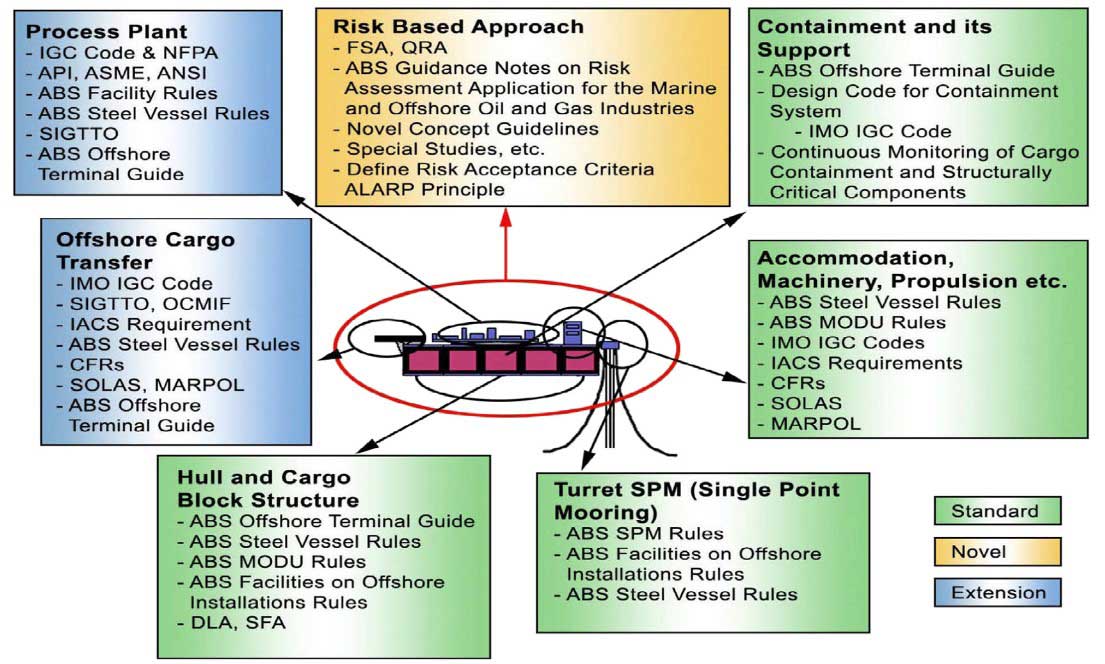
FLNG rule and standards
Each component of the FLNG design must comply with the appropriate rule and standards. The diagram shown in Picture 4 identifies the required rules and standards that are to be used as guidelines for the design.
Design challenges
There are many design challenges and solutions that may be used in configuring an FPSO design (Wood et al., 2007; Wood, 2009). Some of these design options are described next.
LNG storage
The transport of LNG in marine carriers is well established. However partial fill conditions in an FLNG facility is the prevailing status as the LNG is processed prior to off-take. This may result in sloshing,which is of particular concern in membrane tanks. The consideration of loss of containment must be addressed when considering hull fabrication.
The use of concrete for the hull provides benefits in the storage of cryogenic fluids as it retains its structural integrity when in contact with the LNG but traditional steel ship designs are cheaper to build. The self-supporting, prismatic Type B (SPB) LNG tanks offer some advantages in regards to FLNG over the dome or Moss tanks in that they provide robust tanks but also allow a flat deck space for process equipment.
In any design, a catastrophic tank failure may result in serious structural damage to the offshore facility. Design to avoid such an occurrence and methods to mitigate the problems must be addressed in the offshore designs.
There are generally four different types of cargo containment systems for FLNG. The design details were discussed earlier. These cargo types can be compared in terms of the:
- main concerns on partial filling;
- sloshing;
- topside support;
- and maintenance as given in Table 1 (Janseens, 2012).
| Table 1. Cargo Containment System for LNG Carriers | ||||
|---|---|---|---|---|
| Containment System Main Concerns | MOSS | SPB | Membrane Single Row | Membrane Double Row |
| Partial Filling (Sloshing) | Very Robust | Very Robust | Limited impact resistance | Centreline bulkhead prevents sloshing |
| Tank shape prevents sloshing | Centreline bulkhead prevents sloshing | Full width tanks prone to sloshing | ||
| Topside Support | Very limited deck space available | Plenty of deck space | Plenty of deck space | Excellent deck space |
| Full width modules only | Full width modules only | Centreline bulkhead can support modules | ||
| Maintenance on site | Excellent accessibility to tank structure | Poor accessibility inside tanks | Poor accessibility inside tanks | |
| Requires staging | Requires staging | |||
| Other | > 100 ships in service | 2 ships in service | > 230 ships in service | Long. Cofferdam heating required |
| Mainly Japanese Shipyards | 1 supplier (IHI) | Many yards | ||
| Expensive | ||||
| (Janseens, 2012) | ||||
Marine offloading of LNG cargo storage
Offloading LNG in a marine environment requires bulk LNG carriers to approach and berth either in parallel (i.e., alongside a floating facility) or in tandem. This is routinely achieved for crude oil cargoes in various designs of floating production storage and offloading (FPSO) facilities, but constitutes a major hazard concern for the offshore option. There are hazards associated with potential collisions with approaching LNG carriers. Also the offloading dynamics must be designed to cope with relative motions between the floating structure and the ship that exceed those expected from shore-based jetties.
If offloading is considered with a typical spread-moored configuration such as might be found offshore West Africa, then side-by-side offloading could be considered. This provides the benefit in that typically LNG carriers load at midship, providing more flexibility.
However in less benign seas, weathervaning and tandem offloading configurations are more appropriate. To facilitate this, a number of technology suppliers have designed flexible loading arms for transfer of LNG between the production vessel and the tanker such as the SBM soft yoke mooring and offloading (SYMO) system (Sheffield and Mayer, 2001; Faber et al., 2002; Poldervaart and Oomen, 2006).
Side-by-side transfer.Side-by-side transfer involves maneuvering a shuttle carrier alongside the FLNG, temporarily mooring the two vessels together, separated by fenders, conducting the transfer operation via connection to the carrier’s midship manifold, then unmooring the vessels. Maneuvering would usually involve assistance of tugs. This operation has similarities with transfer at land-based terminals.
The main side-by-side technologies are:
- Rigid arms with extended envelopes and assisted connection.
- Aerial hoses.
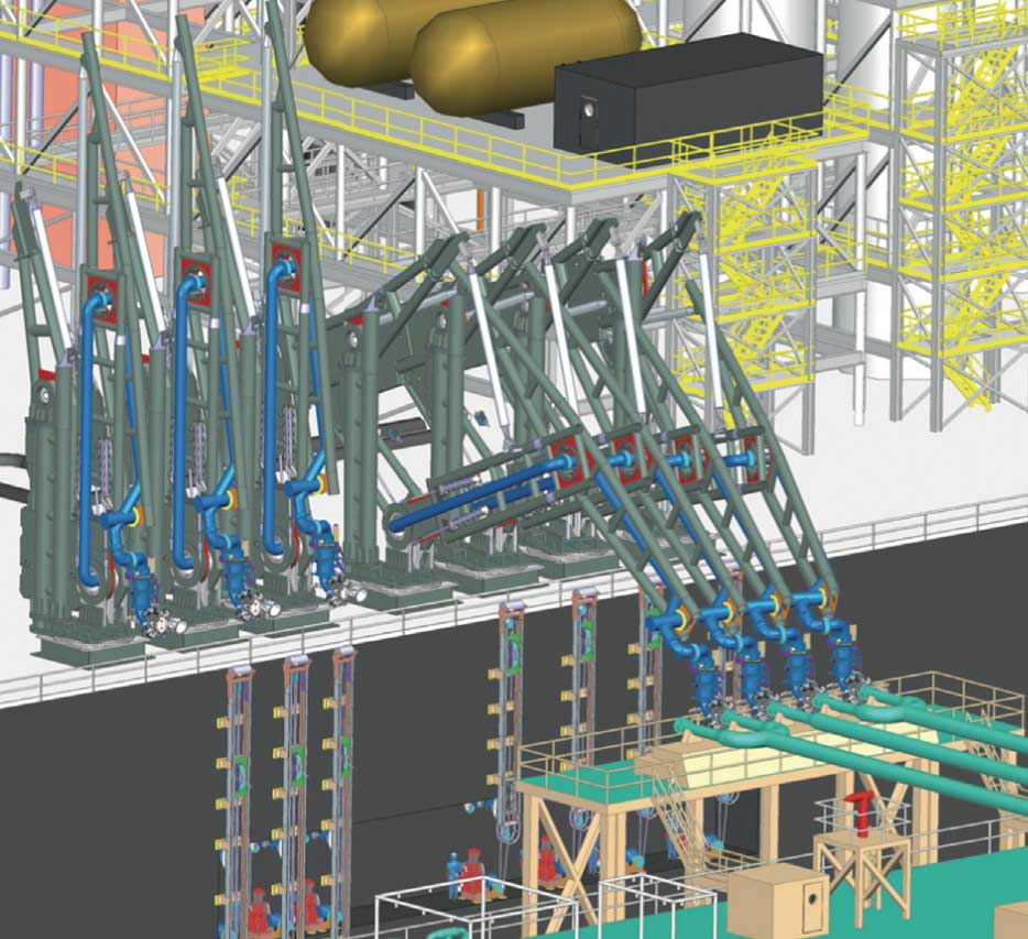
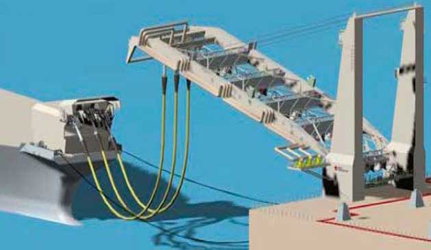
FMC has developed a loading arm system for the subsea and topside equipment for Shell’s Prelude floating LNG project. The OLAF (Offshore Loading Arm Footless) system will build on FMC’s existing Chiksan LNG loading technology, which is based on articulated rigid pipes equipped with Chiksan swivel joints and supported by a separate articulated structure. FMC will supply a total of seven loading systems: four for liquefied natural gas and three for liquefied petroleum gas.
The OLAF has no base riser; instead, the articulated assembly is bolted on a turntable at deck level, which allows a 20 % reduction in the length of the arm and connection to carriers up to 10 m below Prelude’s deck. The advantage is that the OLAF can reach a very low operating envelope to accommodate the large differences in height at deck manifold level that can arise between an LNG shutter tank and FLNG. An artist rendering of the system is shown in Picture 5.
Tandem transfer. Tandem unloading will require LNG carriers purposely built with a bow manifold.The vessels are connected by hawser line and transfer is from stern of FLNG to bow of shuttle tanker.However floating hose solutions may also permit connection to midship manifolds.
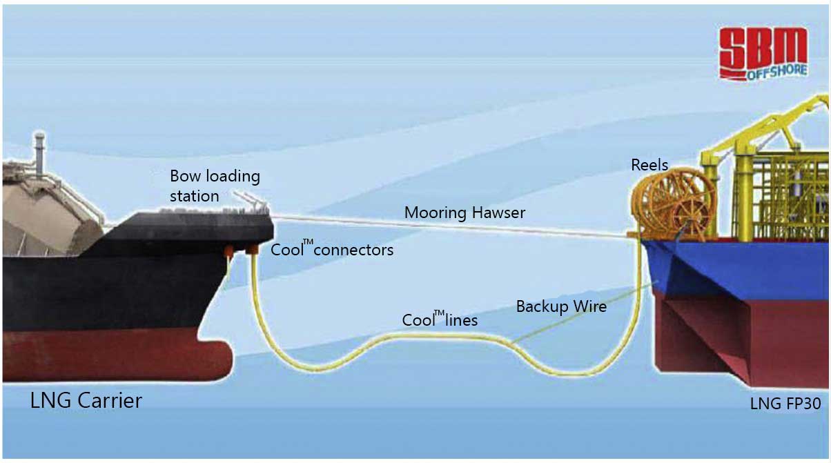
Currently, several vendors have certified hoses for LNG service. The system is composed of a flexible cryogenic floating LNG hose and connectors designed to allow the transfer of LNG between vessels in a tandem moored configuration, exactly the same way that traditional floating oil and gas facilities carry out cargo transfers.
Picture 6 shows a rendition of the tandem transfer proposed by SBM using SBM’s COOL™ hose design. The hose comprises an outer marine hose with an inner composite LNG hose, with the space in between filled with insulating materials. The connector system is a quick connect/disconnect system that handles and connects the hose to the LNG Carrier bow manifold (Malvos, 2012).
Picture 7 shows another hose system proposed by Framo Engineering and Aker Solutions. The OCT system is based on adopting the tandem ship-to-ship configuration for crude oil loading operations. The system allows 100 meters separation between the vessels during transfer, thereby maintaining a high level of safety during all operations. The system consists of three flexible pipes – two for LNG transfer and one for vapor return-suspended from movement-free swivels and supported by an A-frame-type crane.
When the LNG carrier is in position for connection, the A-frame is lowered and the pipes are simultaneously pulled over to the bow coupling manifold using the carrier’s pull-in winches and receptacles. The pipes are then pulled in position one by one and locked to their respective bow coupler (Pusnes News, 2012).
Geopolitical challenges
The floating LNG (FLNG) technology has taken more than two decades to reach commercial reality.The hurdles are not all technical and operational. Geopolitics represents another formidable stumbling block. Countries that stand to gain the most from floating liquefaction plants, like Nigeria, for example, often insist upon substantial local content in its manufacture, which is almost impossible to accommodate on a commercial basis. Most governments also prefer the guarantees of long-term deployment, local direct and indirect employment that an onshore facility provides. On the other hand, in some regions placing LNG production facilities a significant distance from shore can remove actual or perceived public safety risks compared to the onshore alternative. Similarly, environmental impacts associated with initial site planning approvals and future decommissioning and site restoration become less onerous for offshore, particularly for floating facilities (Wood et al., 2007).
Kerbers and Hartnell (2009), and White and McArdle (2009) provide a comprehensive review of development issues of LNG FPSO projects as an independent and informed basis for organizations to consider as they develop offshore gas projects to fit their individual circumstances and strategies.
Offshore LNG regasification
Floating regasification terminals (FSRUs) can provide a flexible and economic alternative to building land-based LNG receiving terminals. The floating installations may either be located near-shore (e.g., alongside a pier or a jetty) or offshore (permanently moored to the sea floor). Such terminals are supplied with LNG from visiting gas carriers. Depending on their mode of operation and local regulation these FSRUs can be considered either as ships or as offshore installations.
Vessels that transport LNG, connect to an offloading buoy, regasify and discharge their cargo, then disconnect and leave to collect a new cargo are termed Shuttle Regasification Vessels (SRV). These are not normally considered as FSRUs and are readily addressed within maritime classification. SRVs will therefore not normally be engaged in continuous regasification operations and typically will not receive and regasify LNG simultaneously.
FSRUs may either be purpose-built or be converted from existing vessels, typically LNG carriers. Depending on the application the extent of modification to an existing unit will vary; for example,installation of a turret (internal or external) on an offshore moored FSRU or location of loading arms on the FSRU, or on a jetty for a near-shore FSRU.
LNG regasification vessels (LNG RV or shipboard regasification vessels [SRV]) have operated successfully over the past decade around the world (e.g., Gulf of Mexico and offshore New England in the United States, Teeside in the United Kingdom, Kuwait, Dubai, Brazil, and Argentina). An LNG RV has an onboard regasification facility in addition to the conventional LNG carrier’s cargo containment tanks and the offshore mooring capability (Picture 8).
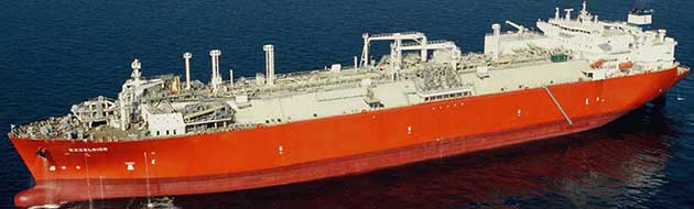
The Gulf Gateway LNG RV was the first offshore LNG facility to be deployed in the world in 2005 and has since been decommissioned. (Lee et al., 2005).
The LNG RV offers significant flexibility because of its standardization, interchangeability, and quick deployment to a range of potential locations. The ability to unload its cargo as gas by latching onto an offshore buoy, through a gas manifold through a jetty docked in port, or conventionally as LNG makes these vessels attractive for seasonal or intermittent deliveries to smaller LNG customers. They can avoid the long lead time and high cost of building a land-based regasification plant or can be used as an interim solution while more permanent and larger-capacity land-based systems are built.
The Gulf Gateway, the Energy Bridge regasification ship that was developed by Excelerate, was the first offshore LNG facility to be deployed in 2005 (Lee et al., 2005). This system involves the use of purpose-built LNG tankers incorporating regasification technology and has demonstrated the capability in supplying fuel gas to the Gulf areas during Hurricane Katrina in August 2005.
Höegh LNG and GDF Suez developed the Neptune Deepwater Port (DWP) around two LNG RVs,which became operational in 2010. It is located 10 miles off the coast of Massachusetts and involves an offshore terminal with two buoys and associated pipelines to shore. The two vessels, GDF Suez Neptune (delivered 2009) and GDF Suez Cape Ann (delivered 2010), were built by Samsung Heavy Industries in Korea specifically for the Neptune project. The vessels incorporate the reinforced GTTMKIII cargo containment system with 145 000 m3 cargo carrying-capacity at 100 %. They are fitted with three regasification skids for a total output capacity of approximately 21 million standard m3 of natural gas per day (~0,75 bcfd), and are also fully capable of operating as standard LNG carriers.
As of today, there are over 10 offshore regasification vessels built and more than two dozen others are in various stages of development. The underlying enabling technologies such as ship to transfer are well demonstrated and are now almost universally accepted as a viable solution in LNG delivery.
Submerged buoy systems
A deepwater port facility usually involves one (or perhaps two) submerged buoys and subsea facilities in one defined location. As the submerged buoy location is known to approaching LNG ships, it is possible for them to locate the mating site with the aid of a differential global positioning system. In the vicinity of the submerged buoy and during the buoy-connection operation an acoustic positioning system is also used to confirm the buoy’s exact location and as a self-reliant sensing device. The submerged buoys are fitted with transponders, so the location of the submerged buoy can be detected by a shipboard acoustic transceiver. To approach the mating site and to assist positioning the vessel over the buoy center, the LNG RV vessel is equipped with bow and stern thrusters to provide dynamic positioning.
The LNG RV is moored via its turret system to the submerged buoy, and is free to weathervane around the turret to minimize the drag and ship motion during the regasification operation (e.g.,Leeet al., 2005). The vessel motion in the moored position is more restricted than when the vessel is sailing or unattached from the buoy. A swivel system provides a high pressure natural gas connection between the weathervaning LNG RV and the fixed submerged buoy (Kim and Lee, 2005).
The normal buoy connection and disconnection takes approximately 1 to 3 hr, but in an emergency situation, the buoy can be disconnected very quickly, in approximately 15 min, and the LNG RV evacuated to a safe location. The vaporized natural gas from the regasification system is connected to the swivel mechanism and submerged buoy through an onboard flexible riser.
The turret system typically includes:
- submerged buoy locking mechanism;
- rope guider;
- traction winch;
- swivel-handling system;
- flexible riser;
- closed-circuit TV;
- hydraulic;
- and control system.
The rest of the subsea system to which the submerged buoy is attached is composed of a subsea riser, pipeline end manifold (PLEM), and subsea pipeline. The buoy typically is located approximately 25 m below the sea surface and moored by a number of spread mooring lines and requires a minimum overall water depth of about 30 m. Shutdown valves and transmitters are located in the PLEM and can be operated by the onboard LNG RV control system. There is usually the requirement for an independent gas metering system to facilitate custody transfer of natural gas dispatched shoreward in the high-pressure gas pipeline.
Offshore regasification safety
In addition to the normal shipboard control system, an emergency shutdown (ESD) system is required to shut down the critical valves and the subsea equipment in emergency situations. The integrated LNG RV ESD system needs to coordinate the safety features for the:
- regasification;
- turret;
- buoy;
- and PLEM systems.
During regasification the LNG stored in the vessels cargo tanks is fed into a suction drum. High pressure pumps take the LNG from the suction drum and send it to the high pressure vaporizers. The LNG is vaporized in the vaporizers and fed to the export gas pipeline network through the turret system. Most LNG RVs are equipped with an alternative gas offloading system for use when at a port jetty, which flows gas through a midship high pressure natural gas manifold.
Protection against LNG spillage and high pressure natural gas leaks are the main concerns during offshore regasification operations onboard an LNG RV. The high pressure LNG lines between the high pressure pumps and the vaporizers typically are kept short to reduce the risk of high pressure LNGs pillage. The LNG handling parts of the regasification area typically are protected by stainless steeldrip trays and pans to safely collect any LNG spillage.
The flange parts of high pressure natural gas lines also typically are protected by shield devices to isolate and deflect jet flames. In addition a deluge system is provided to the regasification area, and sea water is kept flowing to the protection shield and drip pan continuously during regasification operations. Water spray and gas detection systems also typically are provided in the regasification area.
Floating storage and regasification units (FSRU)
The function of the FSRU is similar to that of the LNG RV. The FSRU and the LNG RV can compete with onshore LNG receiving terminals offering speed-of-deployment advantages in the parallel processing of regulatory authority permissions and facility design and construction. FSRUs can be designed and built to include more storage capacity than that of LNG RV, which has the cargo containment size of an LNG carrier (Lee et al., 2008).
The storage capacity of FSRUs is typically in the 145 000 m3 to 350 000 m3 range and is determined by the cargo tank size and visiting frequency of the shuttle LNG carriers, taking into account storage capacities to compensate for potential supply interruptions caused by weather conditions. In some cases standard LNG carriers are converted to operate as small FSRUs.
The typical regasification capacity for an FSRU is in the range 0,5 and 2,0 bcfd (billion cubic feet per day) and is not only driven by the storage capacity of the FSRU vessel. Regasification capacity can be increased, as necessitated by market demand, provided sufficient space for power generation and regasification equipment is assigned in the design stage. FSRUs can be permanently moored in distant offshore locations utilizing turret systems or moored adjacent to a jetty in port.
When necessary, FSRUs can be designed to have thruster-propelled dynamic positioning systems for extreme weather conditions. The regasification is typically by seawater or heat from onboard boilers.In some port areas seawater discharge from vaporizers is not permitted or in areas where seawater temperature is too cold, onboard boilers or other heating sources are used for the regasification operation. However, this adds to the regasification operating costs. In FSRUs, gas turbines usually are used because of the convenient availability of fuel and efficient heat recovery from gas turbine exhausts.
There are a number of projects in the planning and construction stage for LNG RV and FSRU vessels around the world (e.g., Indonesia, Lithuania, and East Mediterranean), which testifies to their growing popularity.
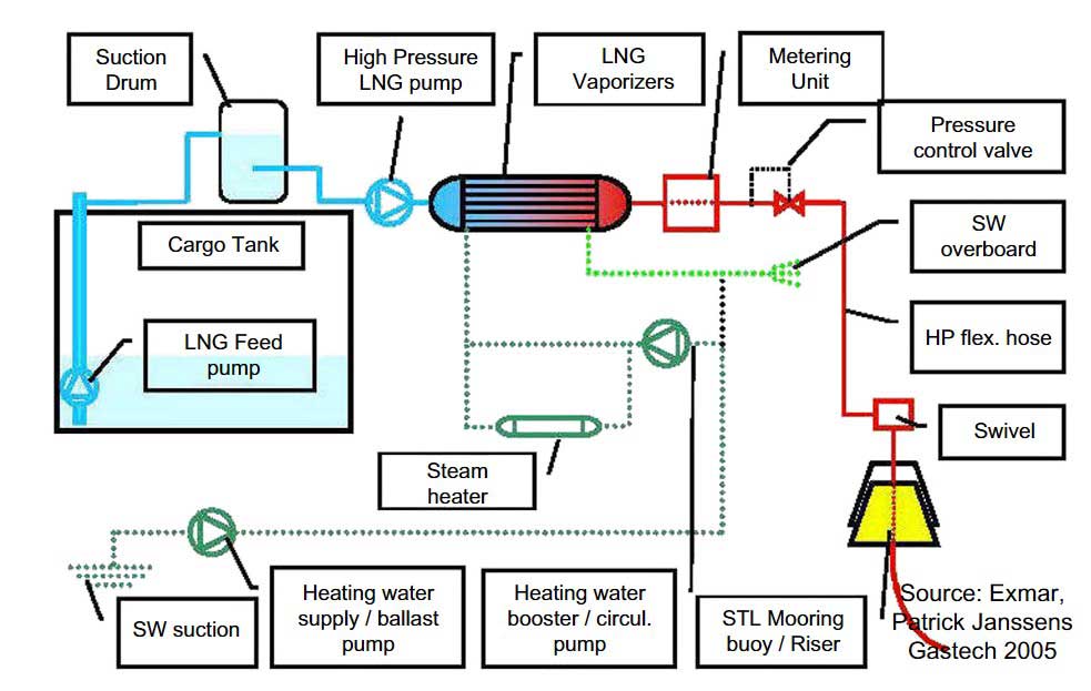
The process units in an FSRU are basically the same as a land base regasification plant. Picture 9 shows the different process units in an FSRU.
FSRUs can be used to supply fuel gas for power generation of a medium-size power plant. Generally when used for power generation, the LNG sendout requirement is relatively low.
For example, with an efficient combined cycle design, the regasification plant sendout requirement is only about 100 mmscfd in order to generate about 400 to 500 MW electric power.
Compared to land-based terminals, the boil-off rate from an FSRU is much higher, at 0,1 volume % per day, compared to 0,05 % of a land-based tank. To avoid loss of natural gas from the BOG, a vapor recovery system should be installed, either with a BOG recondenser, a vapor recovery compressor, or a BOG liquefaction unit.
If the FRSU is to operate in the arctic area, seawater can be used during summer operation. During winter, because of the cold seawater, supplementary heating is necessary using a heat transfer fluid and steam heater, as shown in Picture 9.
Gravity-based offshore regasification units
Fixed offshore structures offer an alternative to onshore and floating facilities for regasification of LNG. These could take the form of artificial islands, fixed platforms, or gravity-based structures (GBS). It is the latter of these options that has been developed so far.
The world’s first offshore GBS LNG receiving terminal is located in the northern Adriatic Sea 15 km off Porto Levante, Italy, where it is capable of supplying about 10 % of Italy’s natural gas requirements. The Adriatic LNG terminal is designed to store and regasify LNG to deliver some 775 mmscfd of gas (8 bcma) and it reached that operational capacity in 2009. The facility is majority owned by ExxonMobil and Qatar Petroleum and it receives LNG primarily from Qatar.
The Adriatic LNG terminal was built in Algeciras, Spain and upon completion in 2008 was floated and sailed via a 3 000-km trip to its location off Porto Levante. It is situated in a water depth of some 30 m (95 ft) and is connected via pipeline to Italy’s natural gas grid. The GBS structure houses in its concrete skirt two LNG storage tanks, a regasification plant, and facilities for mooring and unloading LNG vessels. The concrete used is adapted to handle contact with, and contain, cryogenic liquid in the event of a spill.
Also included in the facility are:
- an accommodation unit for its operating crew;
- gas metering units;
- an emergency flare system;
- power, and other utility systems.
GBS structures are generally more expensive and time-consuming to build and install than LNGRV and FSRU, but offer more permanent facilities that can be expanded in phases over time, if necessary. They do pose more significant decommissioning costs than floating alternatives.
Heating value control in offshore LNG regasification plants
When rich LNG with high heating values is being imported, they may not meet the local gas specifications in terms of Wobbe Index and heating value. In such a situation, the propane and heavier components can be separated from the vaporized LNG using fractionation. One of the processes that can be used for managing the heating value of the vaporized product is a patented process (Mak, 2012) as shown in Picture 10. The conceptual process consists of an offshore regasification plant and an onshore LPG extraction plant.
The offshore plant uses the Rankine power cycle to supply heat for LNG regasification while generating power for the offshore facility. The Rankine power cycle can produce sufficient power for the offshore consumption without the use of fuel.
As shown in the flow diagram, LNG from the storage tank is pumped by the low pressure LNG pump to an intermediate pressure such as 100 psig, and then pumped by the high pressure LNG pump to supercritical pressure, typically 1650 psig or higher. LNG is then heated and partially regasified to about 0 °F using the condensation duty from Rankine power cycle (see Chapter 10).
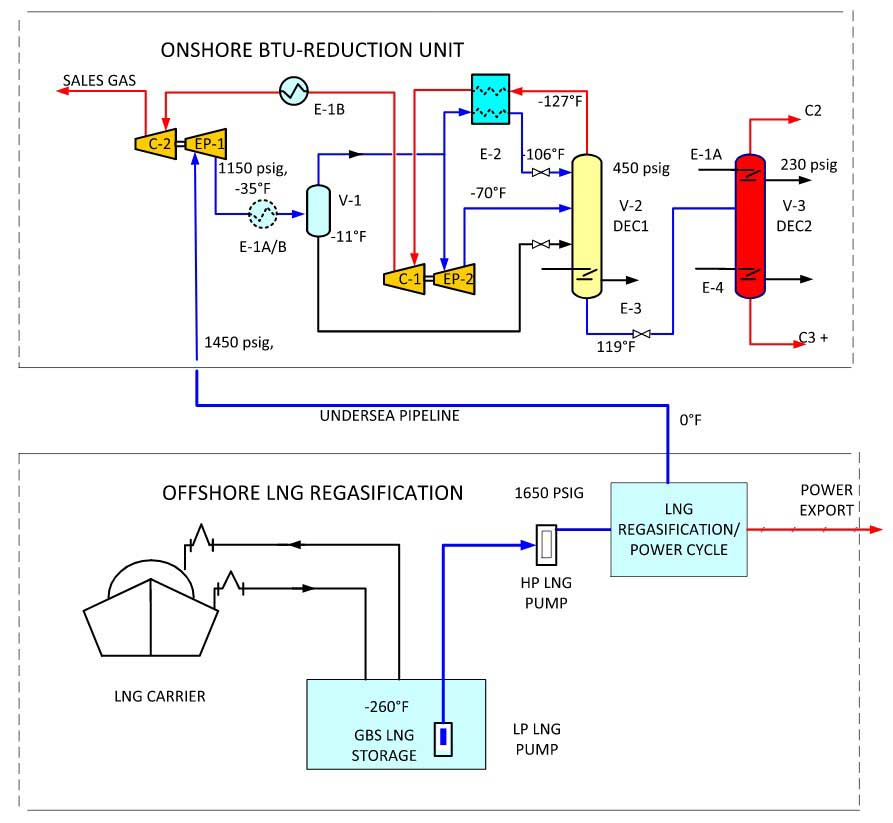
It is important to note that the LNG is only partially regasified to 0 °F instead of completely regasified to 40 °F. Also the operating pressure of 1600 psig is higher than the final gas pipeline pressure requirement. The high pressure (supercritical) and low temperature of the semi-regasified LNG effectively preserves the refrigeration content in LNG that is needed in the offshore fractionation facility. Also the regasification duty at 1650 psig and 0 °F is significantly less than that of the typicallower regasification design, hence reducing the heating duty in the offshore equipment.
The supercritical fluid arrives onshore at about 1 650 psig and is let down in pressure to about 1 100 psig in the first stage turbo-expander, which generates power to operate the second stage residue gas compressor. The expansion process also chills the feed gas to a lower temperature. The refrigeration content of this stream is utilized in the deethanizer reflux condenser for separation purposes.
The heated streams arriving from offshore are partially condensed and separately fed to the demethanizer. To improve NGL recovery levels, vapor is split into two portions; one portion is routed to the reflux condenser and the other portion is let down in pressure in the second stage turbo-expander, which chills the gas, supplying the cooling duty for fractionation in the demethanizer.
The process can also operate in an ethane recovery or propane recovery mode by varying the refrigeration usage from LNG. Very high recovery can be achieved with this process utilizing the free refrigeration from LNG.