The stern gear of a boat comprises the essential components located at the rear (stern) of the vessel, responsible for its propulsion and steering. Central to the stern gear is the propeller, which converts the engine’s power into thrust, propelling the boat forward or backward. The propeller is connected to the engine via the propeller shaft, which runs through the stern tube. This tube is a watertight casing that also houses bearings to support the shaft and maintain smooth rotation while preventing water from entering the hull. Additionally, the strut, an external support, holds the propeller shaft in place and often contains a bearing to further stabilize the shaft.
Steering is managed by the rudder, a vertical blade positioned behind the propeller, which directs water flow to change the boat’s direction. The coupling, another key component, links the engine to the propeller shaft, ensuring efficient power transfer. To protect the metal parts of the stern gear from corrosion, sacrificial anodes are attached, which deteriorate over time in place of the more critical components. Together, these elements of the stern gear ensure the boat’s propulsion and maneuverability, making them vital for the vessel’s overall operation.
STERN GEAR IS so often out of sight, out of mind, to the point that it is probably one of the most neglected areas in boat maintenance. Boats can go a whole season or more without anyone sighting and checking the stern gear and yet this can be one of the most critical parts of a boat, since any neglect can quickly lead to disaster. Obviously the boat has to be out of the water to Technical Advice on the Boat Inspection Process and Why Survey Your Own Boatsurvey the stern gear and all boat owners should take every opportunity (for example, when the boat has been lifted out for a quick paint or it has just dried out over a tide) to check it.
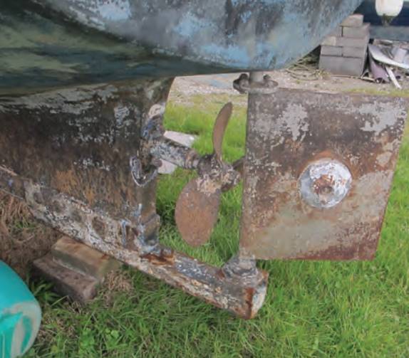
There are two aspects to any failure in the stern gear. First, you may lose either the propulsion or the steering or possibly both, which can immobilise the boat in a way that may be difficult or impossible to fix at sea. Second, a failure could lead to water getting into the boat, which will add to the drama of the situation! So the moral is, don’t take any chances with the stern gear when you inspect it and take special care over it when you do.
Propeller and shaft
LET’S LOOK AT the propeller and its shaft first, since virtually every boat, both power and sail, will have this in one form or another. One of the simplest propulsion installations is an outboard motor and the benefit here is that there are no through-hull openings to be sealed. on a larger outboard powered boat you should check the areas around the engine mounting because this can be under considerable stress at times and you may find some cracking of the gel coat to indicate this (see articleRIBs and Tenders on Yachts“Read More About How Ribs and Tenders are Used on Yachts” for further advice on surveying outboards).
Support and Bearings
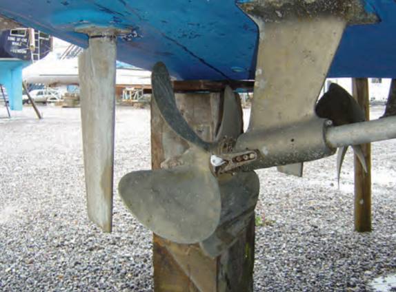
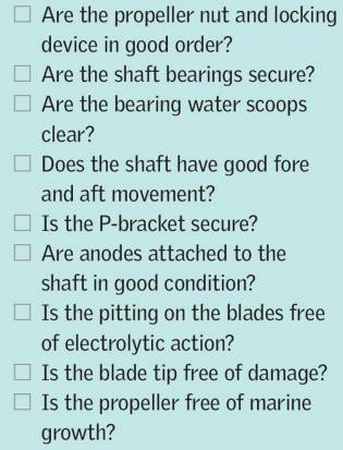
For boats with a conventional shaft and propeller system you need to examine several areas. First, try lifting the propeller and its shaft and moving it to and fro at the propeller end. Any movement indicates there is wear in the shaft bearings or the shaft itself, and if you find it here move on to the P-bracket, which supports the shaft close to the propeller, and perform the same test. P-bracket bearings are usually hard rubber with grooves in the rubber which allow water to flow through, lubricating the bearing. A small amount of movement is normal here because obviously the rubber cannot be a tight fit around the shaft, but any excessive movement, say more than a couple of millimetres, could indicate bearing wear and requires further inspection.
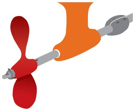
The shaft and bearing can take a lot of abuse, particularly in water where there is a lot of suspended sediment, leading to abrasive material flowing through the bearing. The hard rubber bearing is designed to clear this debris, and it works very well, but if it is showing signs of wear it won’t get any better. You’ll need to establish whether the wear is in the bearing or on the shaft itself, which could mean removing the propeller, releasing the grub screws that hold the bearing housing in place and sliding it out, which should also give you a view of the area of the shaft that lies in the bearing.
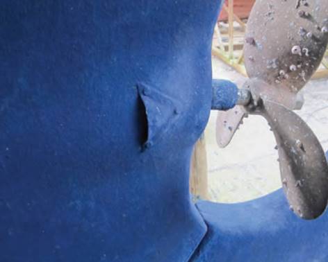
The bearings are generally very reliable and do not wear a great deal, so if you find excessive movement in the propeller shaft the chances are it will be a shaft rather than a bearing problem. If you do need to replace a bearing it is a relatively simple job. However, if the shaft is the issue you’ll need a specialist to build it up again to its original diameter. Before you go too far down this line check the inlets that allow water to flow into the bearing; on an exposed P-bracket the natural flow of water into the bearing creates the lubrication, but if a rope cutter is fitted it can impede or reduce the flow, which can cause excessive wear.
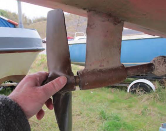
On sailboats you often find that the propeller shaft emerges directly from the deadwood or the hull moulding with the propeller attached directly to the stub of the exposed shaft without a P-bracket or other support. The shaft support bearing may be a water-lubricated bearing fitted with small scoops on either side that direct the water into the bearing.
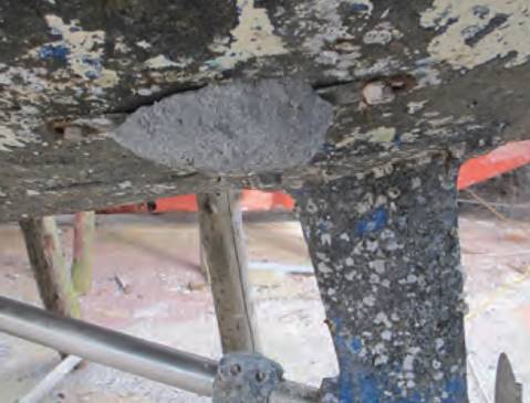
These can get clogged with barnacles or other growth, so if they’re present, check they’re clear and functioning. (While marine growth is usually cleaned off when the boat is taken out of the water, it may be difficult to clear in the hard-to-reach areas, so growth on any propulsion system the rudder could signal low standards of maintenance in general.)
Alternatively, the support bearing can be inside the hull where it may be water lubricated through a pipe attached to the bearing. Finally, and only usually on older boats, it could be a grease lubricated bearing with a screw down cap (you can often detect a grease type bearing from the outside because of oil stains around the point where the shaft exits the hull). If there is movement found in the propeller shaft with one of these installations, you need to explore inside the boat. It may be a case of withdrawing the shaft to check its condition and that of the bearing, which is obviously tricky. It could even mean taking out the engine and gearbox first so that the shaft can be withdrawn into the boat or, alternatively, it may be possible to disconnect the coupling on the shaft and remove the shaft from the stern, although this may entail removing the rudder first.
Stern Glands
Inside shaft bearings are usually combined with a stern gland, which is what keeps the water from entering the boat around the rotating shaft. The stern gland plays a vital role and if the boat is afloat, it should be checked for any dripping water coming into the hull around the shaft. Checking this function with the boat ashore can be difficult, but if someone turns the shaft while you watch it closely you may be able to detect distortion in the bearing, which could lead to leaking and also produce excessive vibration when under way. On older boats it may just be the grease forced into the bearing that is preventing water from entering, so check the shaft for any up and down or sideways movement.
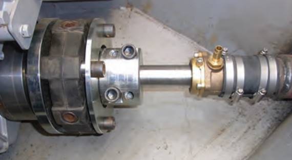
Some stern glands are mounted rigid with the hull and also act as a bearing to support the shaft. This type of installation requires careful alignment of the engine and the shaft to ensure smooth running, and an alternative flexing joint may be included in the drive train to allow for any slight misalignment.
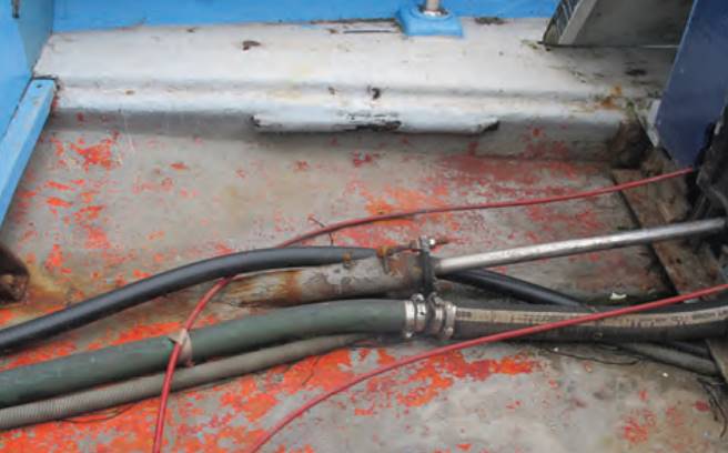
Flexing joints come in many shapes and sizes, such as a mechanical joint of the universal joint type or the more popular type that incorporates rubber sections to help reduce vibration and allow for the movement of a flexibly mounted engine. With either type, check for any wear in the joint by trying to rotate the shaft against the fixed engine. On the rubber type check the rubber for any signs of ageing such as cracks in the surface.

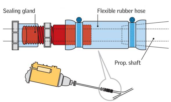
An alternative type of stern gland has the shaft passing through a tube in the hull where it is supported by an outboard bearing. To seal the joint around the shaft a short length of rubber hose is attached to the inside section of the hull tube with its other end coupled to the sealing gland. Such an installation can allow for some movement in the shaft without causing leaks but it relies heavily on the rubber hose and its securing clips to keep the water out. This is a critical bit of hose and it should be checked for any swelling or softness. Ensure there are double clips and that they are free of corrosion, which is more likely on the difficult-to-see parts of the clips underneath the tube.
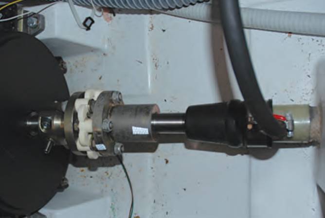
There should be a renewal programme for this hose section just like that for the engine cooling water hoses, but fitting a new section means disconnecting the flange or flexible joint that connects the shaft to the gearbox and drawing the shaft out. If there is a need to dismantle this Complete Guide to Below Deck Sailboat Systems: Ventilation, Marine Heads, Water Systems and morestern seal system do take the opportunity to inspect the condition of the shaft in the bearing for wear.
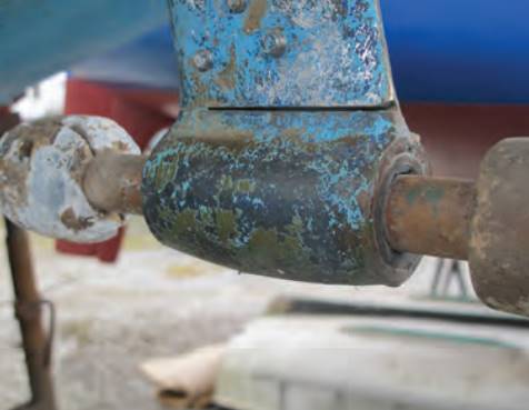
It’s quite easy to check for wear in the propeller shafts of most sailboats and smaller motorboats, but on a planing powerboat the size and weight of the shafts and propellers make it difficult to detect any movement when you try to move them.
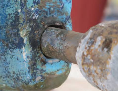
The only solution here, short of dismantling, is a detailed visual inspection: look for bearings that are slightly oval in shape or signs of weeping oil or water at the points at which the shaft log leaves the hull.
It’s difficult to say how much wear is acceptable but if you can see a bearing that is oval rather than round, it requires further attention.
Integrated drive systems
WHILE SHAFTS AND propellers are the main type of drive system found on boats, there is a growing trend towards integrated drive systems such as stern drives, sail drives and pod drives. In each of these systems the whole drive train is fully enclosed and you can’t see what is happening inside without stripping it down. You could check for undue wear or play in the system by putting the drive in gear and trying to turn the propeller. The very nature of the system means there will always be a certain amount of play, but alarm bells should ring if you have trouble turning the propeller by anything less than a significant amount.
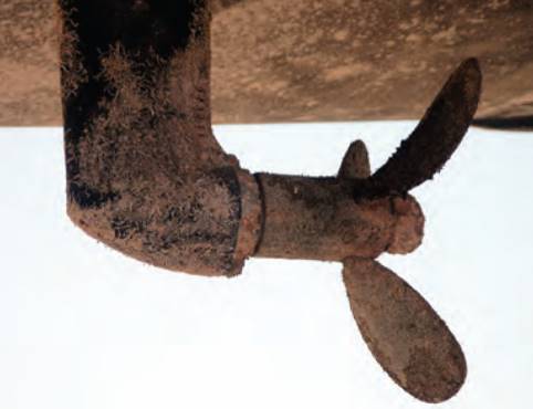
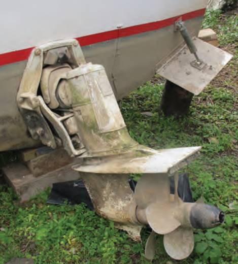
Stern drives are bolted to the transom and their outboard legs are designed to lift up for stowage or in the event of grounding. Flexible connections are built into the drive shaft and the exhaust, while you’ll also need to examine the integrity of the exhaust piping. Check the hydraulic cylinders that do the lifting for any signs of leakage, which you’ll be able to feel when wiping your hand along the pipes or rams.
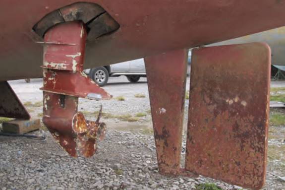
Beyond stern drives, the other Self-Survey Criteria for the Engine and Electrical Systemsdrive systems exit through the hull via a sealed hole, and this is where you should look for trouble. To reduce vibration and make for simpler installation the hole is usually sealed with a rubber gasket, or perhaps even two for security. Inspect these rubber gaskets for any signs of wear or perhaps cracking in the rubber, which could signal that they are nearing the end of their useful life. The manufacturers will probably propose renewal after a fixed period, perhaps ten years as a safety measure.
On sail drives the rubber gaskets are often held in place by large worn drive clips and this is where you should focus your checks for the usual corrosion/damage. The seal where the drive exits the hull is critical to the safety of the boat so even though access can be difficult, do not skimp on this check.
Anodes
Since they often comprise an aluminium casting combined with bronze propellers or other forms of dissimilar metals, each of these integrated drive systems has anodes built into it to protect it from electrolytic corrosion. Anodes are designed so that they, rather than critical parts of the boat, are attacked and eroded, so it is pretty easy to detect corrosion. The anodes may be in the form of a ring around the hub of the propeller unit or in the propeller cone; check them for excessive erosion, which indicates that not only are they doing their job properly but – especially if they are more than half eroded – this could be the time for renewal (note that anodes should not be painted, since it is the exposed bare metal that allows them to do their job).
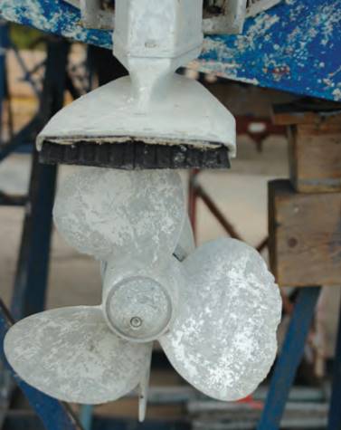
Boats with conventional propulsion systems will also be fitted with anodes of one form or another as a safeguard against electrolytic corrosion. These anodes come in various shapes and sizes; some are bolted around the propeller shaft, another type substitutes the propeller nut, while others may simply be attached to the hull by means of studs with nuts.
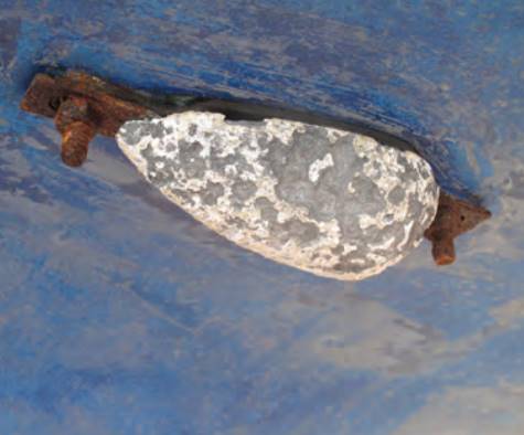
In steel and aluminium hulls where there are vast expanses of metal, anodes are even more vital, so do the same checks for erosion, and anything less than half its original size calls for replacement. It would be nice to think that it’s simply a question of unbolting the old one and bolting on a new one but the securing nuts will often be a struggle to remove – it often means cutting the bolts off and replacing them with new ones.
Inside the boat the various metal fittings and anodes should be linked together with an earthing wire or be in direct contact for the whole system to do its job; check these wire connections because they could be lying in the bilge and the inevitable corrosion in the copper wire and metal fitting can lead to the connection parting company.
Electrolysis
Electrolysis has been something of a nightmare in the past but we now have a much better understanding of why it occurs and how to prevent it. However, this does remain a specialist area and if you have any doubts regarding the deterioration of anodes, call the expert or simply walk away.
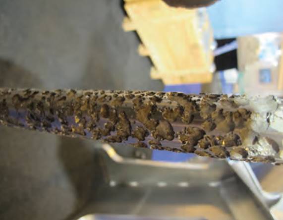
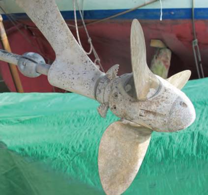
Electrolytic action is usually revealed through pitting in metal surfaces, just like you see in the anodes. The action dezincifies the bronze (attacks the zinc in the bronze as the soft option), which you may see in often pinkish-tinged pitting over the surface of the propeller.
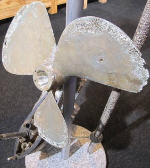
Since propellers are usually bronze or stern drives and sail drives on outboards aluminium alloy, chances are you’ll see this type of pitting upon examination. And, in fact, this can reveal a lot about the boat’s general condition: spot pitting here and you’re likely to find it over most of the surface.
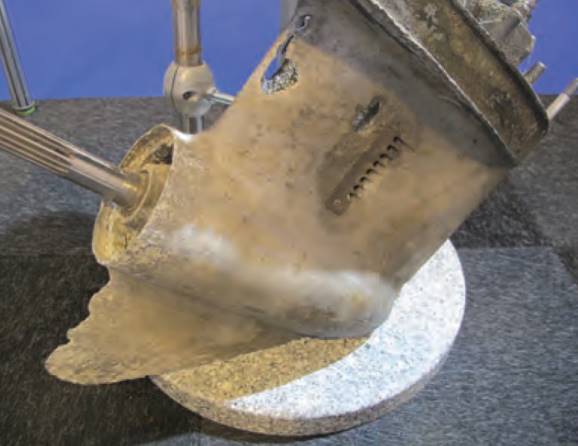
You may well be looking at a replacement propeller, but consult an expert for help in finding the root cause of the pitting before you go down that route.
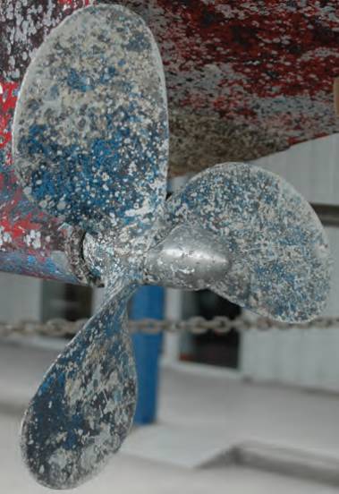
Examine the anodes and the earthing wires over the interior – is there any wiring that bypasses the main battery switch, which could have been earthed and created stray currents?
Any time a boat is connected to a mains supply in the marina the earthing must be meticulous to avoid current leaks.
Other Propeller Damage
Damage to the tips or outer edge of the propeller could have been caused by grounding or striking debris in the water. Either way, any bent or damaged blades may create vibration, adding stress to the entire propulsion system and making life on board uncomfortable! It may be possible to straighten up small areas of tip bending and if bits have actually broken away, propeller specialists can build up the metal again.
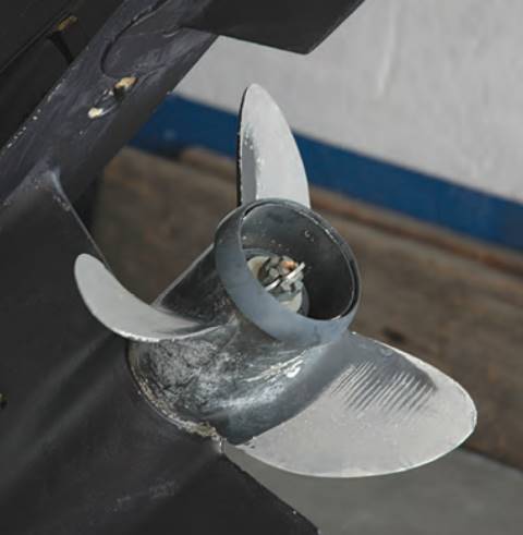
Polishing on the propeller, revealed by shiny surfaces, could indicate that the owner has operated the boat in very shallow water or has perhaps grounded it on a sandy bottom, where the contact has polished the blades rather than damaged them. This is more likely to be seen on aluminium alloy propellers on outboards or stern drives rather than on bronze propellers where any shine will quickly disappear with further use. Propeller cavitation may be found on the propellers of faster boats, usually indicated by areas of polished or pitted blades. Severe pitting calls for a replacement propeller but, again, it’s worth calling in the expert before you take action.
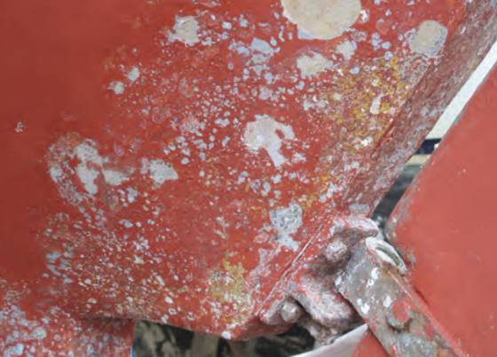
Propellers are expensive bits of kit and you do not want to lose one at sea. Check that the propeller nut(s) are tight up against the propeller. There should be some way of locking the main nut tight to prevent it coming off at sea – it may be a second locking nut or simply a cotter pin that fits through a hole in the shaft and then into slots in the outer edge of the nut. While you are doing this also check that the P-bracket is secure to the hull; it is usually bolted through the hull. Slight movement will show through thin breaks in the antifouling paint around the edge of the plate that is fixed to the hull or around the securing bolt heads. If you see that thin break it could also be caused by vibration rather than a loose fitting, which could indicate that the shaft bearings are worn or the propeller has been damaged. It may be possible to tighten up the bolts from the inside, but it would be best to withdraw the bolts and re-seal the flange.
Feathering Propellers
Sailboats often have a feathering propeller installed. This is designed to reduce the drag when under sail and the propeller is not being used. There’s a variety of feathering propellers on the market, some two-bladed and some with three blades. On most designs they can be opened and closed by hand, so during a survey you can check the propeller’s operation and that there is no undue play in the blade attachment, which would indicate wear in the support bearings.
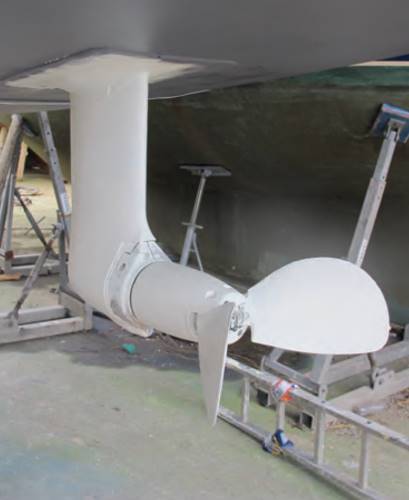
Certain designs have an oil-filled hull to support the blades so be alert to oil leaks around the hub. Feathering propellers are common on sail drives and, with an aluminium alloy drive leg and a bronze or stainless steel propeller, there can be a risk of electrolytic action between the two; check the drive anodes for excessive corrosion.
Water Jet Propulsion
Some fast powerboats may have more exotic forms of propulsion such as water jets or surface drives.
These systems often have exposed hydraulics that you’ll need to check for leaks and corrosion, and in the case of surface drives there may be an external gear box to examine.
Water jets are vulnerable to marine growth inside the jet tunnel, which of course reduces the effectiveness of the propulsion; on smaller jets with restricted access it can be very hard to clear.
Rudder
WHILE THE DRIVE system propels the boat the rudder is your steering control, and one won’t work without the other. However, in many cases the steering system does not get the same attention and maintenance as the propulsion. Steering systems come in a variety of forms and they essentially comprise three parts:
- the rudder or steerable drive leg itself;
- the operating system that connects the rudder to the steering;
- and the steering control.
When the drive leg does the steering, such as in a stern drive, and some sail drives and outboard installations, it replaces the rudder, except perhaps in the case of a sailboat with an outboard where you still need a rudder when sailing. All of these parts are essential to the safe operation of the steering and yet they are often hidden away in the bowels of the boat and may not be easily accessible for inspection.
Rudder Mounts
The simplest form of rudder steering, a transom hung rudder connected to tiller steering, is found on many smaller boats and incorporates all three parts of the steering into one unit. Such an installation is easy to inspect as the components are easily accessible from the outside, but there can still be variations in the way that the rudder is hinged to the transom.
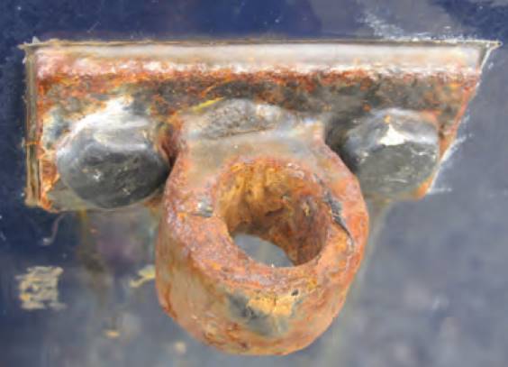
Usually there will be a couple of eyes or gudgeons fitted to the transom where the pintles on the rudder engage, so that the rudder is hinged. here you will be looking for any play in these «hinges» and while a certain amount of play is permissible, if the holes show any signs of becoming oval or the pintles show wear, it could be time for renewal; once the wear occurs it can quickly accelerate, since there will be more movement in the rudder.
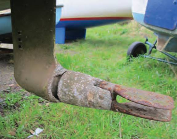
On some smaller motorboats and some sailboats the bottom hinge point of the rudder is often formed by an extension bar running below the propeller and this type of bearing can be more prone to wear because abrasive grit can settle into the socket with no easy means of escape. If there isn’t a drain hole in the bottom it can be a good idea to drill one, at least creating the possibility for grit to pass through the bearing.
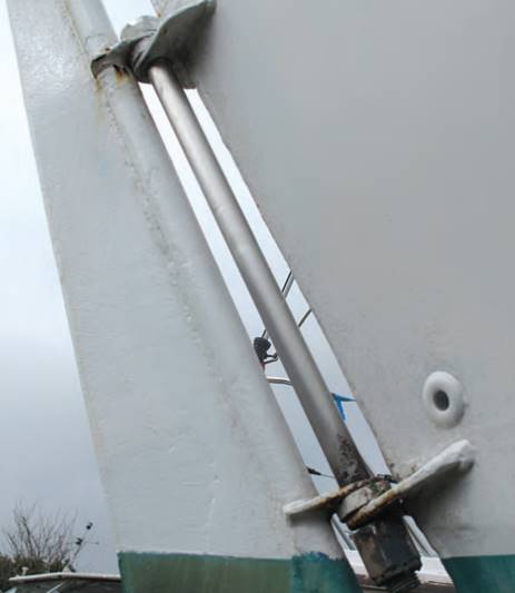
Move the rudder to and fro in order to check that the bearings are reasonably in line and that there is some means of securing the rudder in place so that it doesn’t lift off the bearings in a seaway. This securing may be a nut and lock nut on the bottom of the pintle or it can be a simple split pin through the pintle with a washer between the pin and the socket. To prevent the rudder lifting, some installations rely on the unsatisfactory arrangement of a tiller arm working in a slot through the transom near the deck level; check for signs of wear on the wood or moulding where the tiller arm rubs as the rudder is lifted.
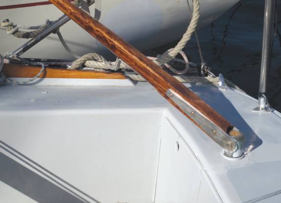
The tiller arm should be tightly fitted to the top of the rudder because, again, any play here will lead to escalating wear and tear. Tiller arms have been known to break off at sea and this is much more likely to happen in rough seas where the strain on the steering increases. A firmly bolted connection between the tiller and the rudder head is better than a socket arrangement because then there should be no play in the connection.
So that it doesn’t take up room in the cockpit when not in use, on some installations the tiller arm may be hinged at the point where it connects with the top of the rudder to allow for upwards movement; again, check this hinge for wear.
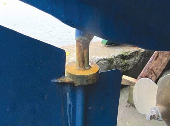
The spade rudder system, where part of the rudder blade is forward of the hinge point to help reduce loading on the steering, is found on many boats, both motor and sail. In this system the bottom of the rudder is unsupported, so that there is considerable strain on the bearings located at the top of the rudder stock. The rudder stock, which on modern boats is usually constructed from stainless steel, enters a tube fixed into the hull; it will have a bearing at the point where it enters the hull and another one higher up. Depending on whether the steering actuator is inside the hull or up on deck there will be a second support bearing at the top of the tube and if this is inside the hull, this top bearing will also incorporate a gland to prevent water getting into the hull.
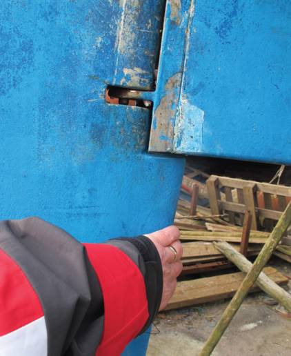
If the rudder stock extends up to deck level, it is likely there will be a tiller attached to the top which makes for a relatively simple installation and one in which there is little chance of water entering the hull.
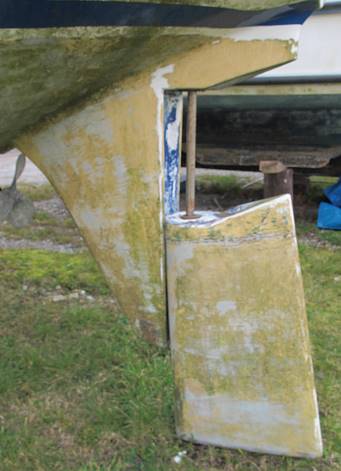
With any type of spade rudder check the system for wear in the bearings by trying to move the rudder from side to side across the boat and then in a fore and aft direction. A small amount of movement is permissible, but if you do find any excessive movement, perhaps in the order of 2 or 3 mm at the point where the rudder stock enters the bearing, you will need to remove the rudder and check the stock and bearings for wear. The bottom bearing of a spade rudder can take a lot of punishment and these bearings usually rely on water for lubrication rather than greasing.
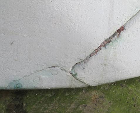
At one point in the system there will be a support to take the vertical load of the rudder, usually at the top of the rudder stock, where there may also be a grease point for both the bearing and the vertical support. If there is play in the rudder stock and its bearings, the sealing gland at the top of the stock may not seal properly, so check here for signs of leaks.
Read also: Basic Hull, Keel, and Rudder Shapes
The tube that provides the supports for the rudder stock may be either metal, and welded or bolted to the hull, or composite, and bonded to the hull. The rudder can be subject to quite high sideways loadings and it is not unknown for the bonding or joint between the tube and the hull to break away and leak. If securing bolts are used they may be subject to corrosion and/or leaks; check closely for any signs of either.
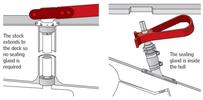
The third type of rudder mounting is where the forward end of the rudder is attached to either a skeg towards the stern or directly to the aft end of the keel. You’ll mainly find this type of installation on a sailboat and it provides a relatively strong mounting, with the rudder supported at both top and bottom. Such a mounting cannot work with a balanced rudder, although there is a compromise design that has a short skeg with the lower rudder bearing halfway up the rudder and the balanced section below.
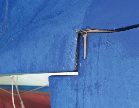
Once again, check the bearings by trying to move the rudder back and forth in line with the bearing area. Also examine the bottom bearing for any signs of movement and corrosion; cracking in the antifouling paint finish at the joint between the hull and the bearing will indicate movement.

It may be just a case of tightening up the securing fastenings, but you may want to go further and remove all fastenings to check for corrosion and wastage.
Rudder Construction
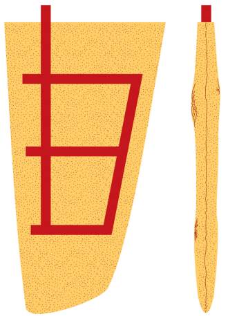
Rudders are constructed in a variety of ways, from metal plates to wooden fabrications and moulded composites. Steel plates welded to the rudder stock are found on smaller craft. A more sophisticated form may include two shaped steel plates formed into an aerofoil section. Whichever the construction, you’re looking for corrosion in the steel.
Cast bronze rudders may be used on fast motorboats and while corrosion is not likely to be a problem here, you might see cavitation erosion caused by the bubbles coming off the propeller front. A small amount of erosion of this type is acceptable, but in severe cases the rudder will need building up or replacing and you may also want to examine the propeller for the same cavitation erosion.
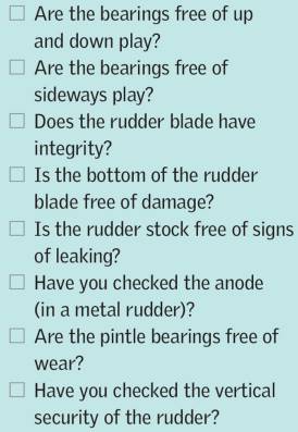
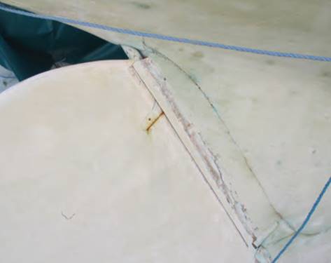
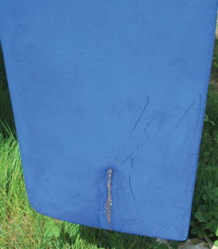
Wooden rudder blades are more likely to be found on smaller craft or traditional designs. The wood is supported by metal strips across the grain of the wood and bolted through. This metal may be mild steel, in which case you’ll be looking for signs of corrosion, particularly around the securing bolts. Composite rudders tend to be moulded around a foam core to create an aerofoil shape and because the rudder tends to be made in two halves, you want to inspect the joint carefully to ensure they are not coming apart. Have a close look at the bottom of the rudder because this is where damage can occur and water can get into the core material, particularly after a grounding.
Steering operating systems
STEERING OPERATING SYSTEMS can vary as much as the type of rudder and again they are largely out of sight, so you’ll need to find access to check them out.
Hydraulic Systems
Many modern boats use hydraulic steering, some of it power assisted. here the pipes connect and translate the wheel movements into movements of a hydraulic ram attached to the tiller head, which then moves the rudder. Check the piping for leaks by rubbing with your hand to see if there is oil on the outside. Ensure that there is full movement of the rudder from side to side and also check the links and connection around the tiller arm for tightness and security.
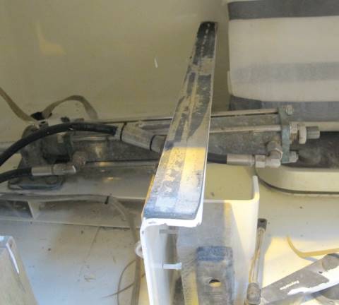
An autopilot may be connected into the system, so check the fastenings for tightness. If you turn the wheel and you feel a sort of lumpiness or hesitation in the movement it usually means that there is air in the hydraulics, which needs bleeding off (instructions for this can be found in the boat’s handbook).
Push Pull Cables
Push pull cables may be used on smaller craft and on outboard and stern drive installations. Here, you can only really check the system for smooth running and inspect the cables to ensure that they have a smooth path free of sharp bends or kinks. Feel free to examine the connections at each end, although these are normally spring loaded ball and socket joints that shouldn’t require maintenance.
Wire and Pulley Systems
The older wire and pulley steering system was a constant source of trouble; wires would regularly part, or fraying and badly stowed equipment could jam the system. If the boat you’re surveying incorporates this system, pull on a pair of leather gloves and run your hand along the wires, feeling for snags.
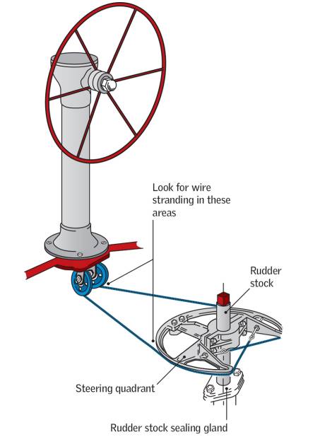
More sophisticated wire and pulley systems are used to connect the wheel with the tiller arm of sailboats and here a quadrant is fitted to the top of the rudder stock with the wires running in grooves around this. Pulley systems guide the wires on the usually short run from the wheel to the quadrant, so check pulleys are free running and wires have good tension and are free of snags. Look for worn wires around the quadrant; any slack here could lead to them coming off and around the pulleys.
Shaft and Gear Systems
Various shaft and gear systems have been used in the past to translate wheel movements into tiller commands and these are generally self-contained and sealed. Therefore, look for leaks around the gearboxes and for signs of anything rubbing against the shaft sections. As with all steering systems, check that there is only slight play between the wheel and rudder movements, which usually means jamming the rudder in the hard over position first. In a good system there should be no more than a couple of centimetres of movement at the rim of the wheel, although more is acceptable in a wire and pulley system.
Additional underwater fittings
ONCE YOU HAVE checked the propulsion and steering systems – the two main underwater systems on any boat – it’s time to move on to the additional underwater fittings.
Flaps
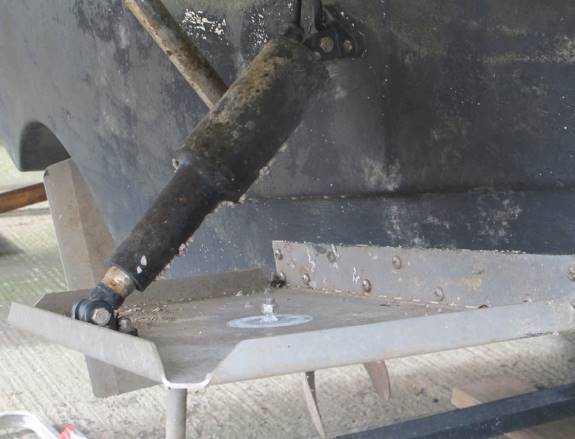
Flaps, usually stainless steel or cast aluminium plates hinged at the bottom of the transom and extending aft, are found on planing powerboats. Move the flap up and down in order to detect any play in the hinges. Flaps are usually operated by self-contained hydraulic rams and these need to be examined for signs of leakage – check the entire system, both inside and outside the boat. As these rams are underwater when the boat is not being used they need to be fully marinised, so any corrosion here should be viewed with suspicion. You will often find that an anode is attached to the topside of the flap as this keeps it out of the water flow at speed, while maintaining its effectiveness when stopped. Be sure to check for any electrolytic corrosion in the form of pitting.
Bow Thrusters
Bow thrusters are found in cross hull tubes set into the front of the hull, so here marine growth is your main problem, especially if the boat has been static in the water for some time. You should be able to turn the impeller by hand and when you do this, check for any play in the drive system (you’re unlikely to be able to turn the hydraulically powered thrusters on larger yachts by hand, although they are less vulnerable to corrosion).
Smaller boats will have an electrically powered bow thruster, where the electric motor is located down in the bilges of the bow. Again, it may be a case of out of sight, out of mind, so carefully examine the electrical connections and the outside of the motor for corrosion.
Additional Bottom Fittings
Engine water intakes, usually a flanged opening with a grill over the intake, are found towards the rear of the hull. Barnacles and marine growth can build up on the grill if the boat is left afloat and unused for some time, so you’ll need to clear it to ensure a good flow of water into the cooling system.
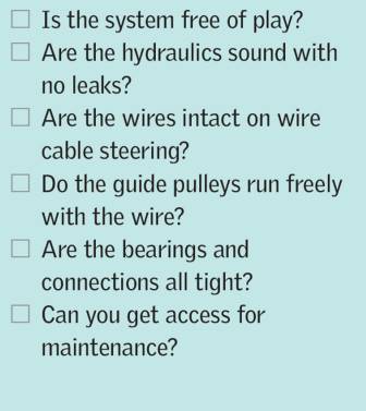
Other bottom fittings such as log impellers or sounder transducers should also be free from growth. Since they are through-hull fittings you’ll also need to check inside the hull for any signs of leakage, as any failure here could sink the boat.

