Transporting gas by sea is not only difficult, but also dangerous. This article covers basic Gas tanker safety precautions and measures.
- Tank atmosphere evaluation
- The need for gas testing
- Oxygen analysers
- Combustible gas indicators Catalytic instruments
- Toxicity detectors
- Entry into enclosed spaces
- Procedures
- Rescue from enclosed spaces
- Fire prevention
- Fire fighting in general
- Management tasks & tactics – fire emergency preparedness
- Fire onboard – Management’s duty
- Plans of Action
- Tactics
- Select an Action
- Extinguishing Tactics
- Fire preparedness
- Alarm instructions
- Extinguishing of fire
- Fixed firefighting plans & firefighting remedy
- Main fire extinguishing plants (For gas and chemical carriers)
- Technical description
- Water – spray system
- Foam in general
- Foam plant
- Pollution prevention
- Pollution in general and its effect on Ecology
- Definition of pollution
- Pollution of air and sea and the influence of ship trade
- OPA90 The American “Oil Pollution Act of 1990”
- The Main Items In OPA90
- MARPOL 73/78
- Personal safety equipment
- Breathing apparatus
- Training
- Protective clothing
- Fire fighter equipment
- Fire stations
- Accommodation
Tank atmosphere evaluation
The need for gas testing
The atmosphere in enclosed spaces must be tested for oxygen and hydrocarbon content in the following circumstances:
- Prior to entry by personnel (with or without protective equipment).
- During gas-freeing, inerting and gassing-up operations.
- As a quality control before changing cargoes.
- To establish a gas-free condition prior to dry-dock or ship repair yard.
The atmosphere in a cargo tank is rarely, if ever, homogeneous. With the exception of ammonia and methane, most cargo vapours at ambient temperatures are denser than air. This can result in layering within the cargo tank. In addition, internal structures can hold local pockets of gas. Thus, whenever possible, samples should be drawn from several positions within the tank.
Atmospheres, which are inert or deficient in oxygen, cannot be checked for flammable vapours with a combustible gas indicator. Therefore, oxygen concentrations should be checked first, followed by checks for flammable and then toxic substances. All electrical instruments used should be approved as intrinsically safe.
Oxygen analysers
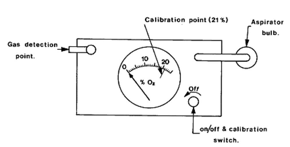
Several different types of oxygen analyser are available. A common type of analyser is illustrated in Pictures 1 (a) and (b). In this example, oxygen diffuses through the teflon membrane into a potassium chloride solution and activates the chemical cell. When the switch is closed, current flows round the circuit and deflects the ammeter needle. The more oxygen absorbed by the solution, the greater the current and the needle deflection indicates the percentage of oxygen in the atmosphere being sampled.
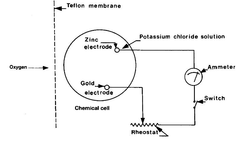
The instrument described above operates without batteries and is relatively insensitive. Other types of analysers include the polarographic and paramagnetic-type instruments. These are much more sensitive and require batteries.
It should be noted that batteries should never be changed in a gas dangerous zone.
Such instruments have dual scales, each having a separate function. For example:
- Scale 1 – oxygen deficiency in air – 0 to 25 % oxygen by volume;
- Scale 2 – oxygen in nitrogen – 0 to 1 % oxygen by volume.
A schematic diagram of the polarographic cell used in some oxygen analysers is shown in Picture 1 (c). In this cell, the current is controlled by the electrochemical reaction of oxygen at the cathode (the permeable membrane). The life of the cell is approximately six months when continuously operated in air.
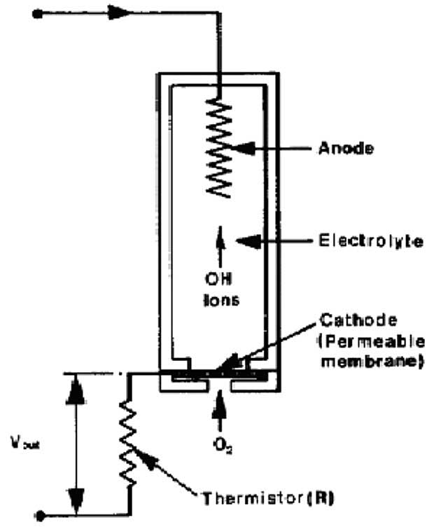
These instruments should be regularly spanned (calibrated) with fresh air (21 % oxygen) and test-nitrogen (a virtual 0 % oxygen content). Liquid contamination, pressure or temperature effects may result in drifting of instrument response.
Combustible gas indicators Catalytic instruments
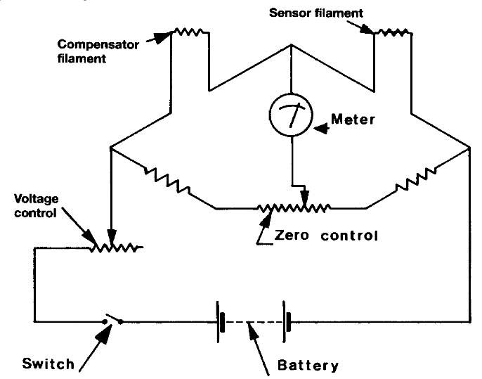
The basic electric circuit (Wheatstone Bridge) of the combustible gas indicator is shown in Picture 2 (a). The gas to be measured is aspirated over the sensor filament, which is heated by the bridge current. Even though the gas sample may be below the lower flammable limit, it will burn catalytically on the filament surface.
In so doing, it will raise the temperature of the filament, increase its electrical resistance and unbalance the bridge. The resultant imbalance registers on the meter, which indicates the hydrocarbon content in the air. Such instruments are designed principally to indicate flammability but are also used to detect the presence of small concentrations of gases in air.
The meter scale commonly reads from zero per cent to 100 % of the lower flammable limit (LFL). On instruments having a dual range, a second scale indicates zero to 10 % of the LFL. Instruments of this type contain batteries, which must be checked prior to use, and it is a recommended practice to check the instrument using a calibration gas at frequent intervals. When calibrating the instrument, the meter reading should fall within the range indicated on the calibration graph which is provided by the manufacturers – see Picture 2 (b).

In the example shown in Picture 2 (b), a meter reading of between 68 and 92 % of LFL for a calibration gas containing 3 % methane in air indicates that the detector filament is in good order. These values are only given for illustration and reference must always be made to the graphs, which accompany each calibration kit.
Tank spaces being sampled which have an atmosphere above the flammable range will produce a low or even zero reading on this type of meter. However, as the sample is initially drawn into the meter, the meter needle will give a momentary strong deflection before returning to its steady low or zero reading. This momentary deflection must always be watched for, since it gives warning that the following steady reading will be misleading and that the gas being sampled is above the lower flammable limit.
Some instruments may have sensor filaments whose catalytic action may be spoilt by the presence of other gases such as halogenated hydrocarbons (halon) sometimes used for fire extinguishing. Whenever opportunity arises, instruments should be checked against each other and any doubt resolved by a calibration kit. It should be noted that the batteries fitted within such instruments should only be changed in gas-safe areas.
Non-catalytic heated filament gas indicators
Since the action of the catalytic gas indicator depends upon combustion with air, it cannot be used for inerted atmospheres because of oxygen deficiency. Instruments suitable for such use, while operating on a similar Wheatstone Bridge principle, contain a filament sensitive to variations in heat conductivity of the sample, which varies with its hydrocarbon content. Such meters usually register over the range 0 to 25 % hydrocarbon vapour by volume and are useful for monitoring inerting operations.
Multipoint flammable gas monitors
The catalytic and heated filament flammable gas indicators are widely used as portable, hand-aspirated instruments. They are intrinsically safe. Their main purpose is for testing cargo tanks, void spaces and other enclosed spaces and this is most often carried out during gas freeing operations and before entry by personnel.
The catalytic instrument is also used in multi-point form for continuous monitoring of air-filled or air-ventilated spaces such as compressor rooms, motor rooms, machinery spaces and cargo holds. In multi-point form, the indicator is installed on ships bridges or in cargo control rooms. These instruments draw samples sequentially from points in the various spaces monitored. The indications may be automatically recorded and individual alarms are provided when a low percentage of the Lower Flammable Limit is detected.
Where void spaces are inerted continuously with nitrogen, the catalytic type will not function and an infra-red analyser is often provided as the central multi-point instrument. Picture 3 illustrates the principle of a typical infra-red analyser.
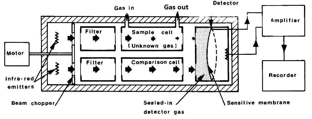
This instrument employs the property of hydrocarbon gas to absorb infra-red radiation. Two similar nickel/chrome emitters within the instrument beam provide infra-red radiation to two separate channels, one through the sample cell and one through a reference cell free of hydrocarbon. The two channels are alternately blocked by a semi-circular beam chopper driven by an electric motor. The transmitted radiation from both channels passes to a detector cell in which the gas is heated by the received radiation. The resultant rise in pressure is detected by the sensitive membrane of a condenser microphone.
As a result of the chopping of the two beams and the absorptive effect of any hydrocarbon in the sample cell, the output of the microphone is an alternating current signal, directly related to the hydrocarbon content of the sample. This signal is amplified and recorded and, when gas is detected, actuates the alarm for the point being sampled.
Toxicity detectors
Toxic gas detectors usually operate on the principle of absorption of the toxic gas in a chemical tube, which results in a colour change. A common type of toxic gas detector is illustrated in Picture 4. Immediately prior to use, the ends are broken from a sealed glass tube. This is inserted into the bellows unit and a sample aspirated through it. The reaction between the gas being sampled and the chemical contained in the tube causes a colour change.
Usually, readings are taken from the length of the colour stain against an indicator scale marked on the tube. These are most often expressed in parts per million (ppm). Some tubes, however, require the colour change to be matched against a control provided with the instruction manual. As tubes may have a specific shelf life, they are date-stamped and are accompanied by an instruction leaflet, which lists any different gases, which may interfere with the accuracy of the indication.
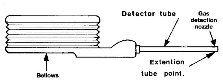
When using this type of instrument, it is important to aspirate the bulb correctly if reliable results are to be obtained. Normally, the bellows are compressed and the unbroken tube inserted. By this means the instrument is checked for leaks prior to breaking the tube. If found to be faulty, it should be replaced. This type of instrument can also be used to good effect during gassing-up operations when changing from one cargo to another. By using tubes suitable to detect trace amounts of the previous cargo, a careful estimation can be made regarding a suitable cut-off point for the operation.
Entry into enclosed spaces
Precautions for tank entry
Because of the danger of hazardous atmospheres, an enclosed space should only be entered when it is essential to do so. At such times a permit to work should be issued and this should be specific as to date, time and space concerned and list the precautions to be taken. Alternatively, for ship tank entry purposes, the Maritime Safety Card should be completed.
The Maritime Safety Card gives an appropriate procedure for entering enclosed spaces on ships. Particular hazards atmospheres can include:
- Amounts of hydrocarbon gas.
- Trace amounts of toxic gas.
- The intrusion of inert gas.
- Oxygen deficiency (often caused by the rusting process in unventilated tanks).
The table below lists those spaces on a gas carrier which are either enclosed or which may be considered gas-dangerous for entry.
| Table. Enclosed Spaces on Gas Carriers Include | ||
|---|---|---|
| Enclosed Spaces in Cargo Area | Enclosed Spaces Elsewhere | Enclosed Spaces Entered Routinely |
| Cargo tanks | Void spaces | Compressor rooms |
| Hold spaces | Bunker tanks | |
| Interbarrier spaces | Cofferdams | |
| Duct keels | Ballast tanks | |
| Spaces containing cargo pipes | Spaces adjacent to cargo spaces having unsafe atmospheres | |
| Note: Even if a space is already considered gas-free and fit to entry, where it is immediately adjacent to a tank having a dangerous and pressurised atmosphere, the space should always be entered with caution and only after suitable checks have been made. | ||
Procedures
For those special cases where tank entry is required, every ship and terminal should have procedures for safe entry and these should be written into operating manuals. Manuals should be clear on questions of area responsibility; shore tanks should not be entered without the terminal manager’s permission and the ship’s tanks should not be entered without the shipmaster’s permission. As far as the terminal operating manual is concerned, such procedures should give advice on terminal operations and the requirements expected from their own, or contracted, personnel when they are visiting or inspecting ships.
Terminal managers should take this matter most seriously, as accidents to shore personnel when entering enclosed spaces on ships are not uncommon. Generally, entry into enclosed spaces should only be permitted when a responsible officer has declared the atmosphere gas-free and fit for entry. Only in very exceptional circumstances should tank entry be allowed when the tank atmosphere is unsafe – and then, only with full protective equipment and breathing apparatus.
Rescue from enclosed spaces
Experience has shown that the rescue of persons from within an enclosed space can be extremely hazardous and especially so in cases of oxygen deficiency. These risks are heightened where access to a compartment can only be achieved with difficulty. In such circumstances, it is vital that rescuers always pay strict attention to the correct procedures and the use of proper equipment and do not rush into ill-considered action.
Many fatalities have resulted from failure to comply with these basic rules. For training purposes, full-scale exercises in non-hazardous atmospheres have been found extremely beneficial. Exercises involving weighted dummies, with rescuers wearing protective equipment and breathing apparatus, are essential if rescue teams are to be properly prepared for a real emergency. Ship’s personnel often conduct such simulations. They can also involve terminal employees and shore based emergency services such as the fire brigade.
Fire prevention
Fire fighting in general
There are two conventions in particular that deals with safety at sea. One is the “International Convention on Load Line”, 1996, that was adopted at an IMO conference in 1996. The other is the “International Convention for the Safety of Life at Sea”.
The Safety convention is a comprehensive convention that intervenes in many areas regarding safety of human life at sea. It starts with the construction of the ship to maintain an as high level of safety as possible due to divisions, stability of the machinery and electrical installations. There are detailed rules for fire, protection, fire discovery and fire extinguishing and of life saving equipment.
Management tasks & tactics – fire emergency preparedness
Fire Emergency preparedness onboard is comprised of the following:
- Sufficient and adequate equipment.
- Organisation and management.
- Training and practice.
Organization and management are essential factors, which deserves a great deal of attention. The leader of the firefighting must, in any case, consider the situation and depending on a number of circumstances execute adequate initiatives. The leader of the firefighting should be able to take care of his/her responsibilities in the best possible way. Essential to this, training and practice must be fulfilled.
Fire onboard – Management’s duty
A fire burst onboard represents a threatening and critical situation. To prevent disaster, a quick and determined effort from the whole crew on board is needed. For most of the people, fire is an unfamiliar event and it is therefore natural that such a threatening occurrence can lead to unpremeditated actions and panicky contributions to the situation.
When this happens, it is the management’s first duty to, as soon as possible, activate the different teams in accordance with the fire instruction plan. Fire resistance arrangements onboard the specific vessel should be utilised to the fullest extent.
If a fire should occur, the management will be confronted with a lot of problems that all seem to be equal in importance. It is important to prioritise when dispersing the tasks. This means that those tasks that seem to be most important must be delegated to the most competent unit or team in the emergency squad. The squad will have to do their best to solve the problems in a satisfactory way. In many cases, the first decisions must be made based on few and uncertain pieces of information about the situation. Any hesitation from the management about which approach to use, will promote the feeling of fear and insecurity among the crew.
Since the crew has been trained in relevant practical skills, the management must also be prepared and trained for the problems they are expected to solve. The ship’s fire instructions must be considered as a tool. The benefit and effect that this tool will give depends on how the management decides to utilise it.
There is nothing that can really replace the valuable experiences you will get by managing extinguishing operations in real fire situations onboard. As this, of course, is practically impossible to accomplish as part of a training programme, other methods have to be tried out. Typically, the standby crew (e.g. fire brigade, first aid teams, civil defence) will need to make quick decisions and judgements of the situation. This type of responsibility requires special training.
Imagine a situation and try to picture the conditions and based on that try to find out how you can, as best as possible, use the resources you have available. This is one way to manage a situation.
However, you have to be aware that in a real situation, the approach to the problem cannot be changed to fit your own perception. By using similar methods onboard, consider imagined fire situations and at leisure find out how to handle the situations, so that the management of the ship can prepare their firefighting duties.
Even though you have worked through a lot of imagined situations, and one day there is a fire, there will never be a situation similar in detail to one of the imagined situations. On the other hand, there will most likely be a situation similar to something you had been through before. In any case you will be better prepared, at least mentally, to manage the situation.
Plans of Action
The more people know the main guidelines for firefighting situations onboard each particular ship, the better the chance for a successful response. Therefore, it is of urgent importance that the management group (The Captain, The Chief Engineer and The Chief Officer) is fully aware of the existing plans.
When considering these imagined situations where you find the best solutions, several points of views will improve the plans. The management group together should work out the plans for the actions for different kinds of fire situations. Therefore, the managers will be informed about the plans, which will make it easier for them to manage accordingly.
In hectic situations, as a fire, it will be easier to change an existing plan rather than making a new plan from scratch.
The plan will be easier to execute, if more people know about its contents. If training is arranged according to appointed plans, the crew will get familiar with the plans in addition to variations in training. Realistic and well-planned training exercises are good practice, as well as, it is interesting and instructive. Successful firefighting is a result of good planning, good leadership and a well-trained standby crew.
Tactics
By tactics we really mean line of action. It is a calculated way to act out a plan of action where we want to use the crew available, in such a way that maximises the effect achieved. The intention with tactics is to reach the goal you have set. You have to be aware of what you want, what is the result you aim for.
In a fire situation, it should be easy to conclude that you want to extinguish the fire, as soon as possible, with as little mess as possible, without any risks to the fire fighters.
Select an Action
When planning a line of action, choose tactics, try to clarify the situation first (reconnoitre). The more details you know about the situation, the easier it is to evaluate the situation. In a critical situation, decisions have to be made quickly. The next step in the planning process will be the evaluation of the situation. Based on the information known, you have to try to determine how the fire will grow. Here it is important to prioritise, as there could be parts of the fire that has to be stopped no matter what.
Meanwhile, other things have to be held off, as long as possible. There are may be some parts that can be temporarily disregarded. With the evaluation of the situation as a basis the disposals of resources are being made. The extents of the contribution depends on how important the effort is, how demanding the work to be done is, and how quickly it has to be effectuated. You should always be prepared to change tactics if unforeseen difficulties occur. Well-prepared tactics considers all known factors whether there are only a few, or many and detailed at any stage.
Extinguishing Tactics
Extinguishing tactics make use of resources available so that maximum effect in an action is achieved. It also makes a sufficient effort at the right place at the critical moment.
- Offensive tactics is a well-known expression; it means that you will use all resources in the fight to win back the terrain and to get the situation under control.
- Defence tactics are when you use the whole force to last as long as possible to prevent being forced to back out, avoid loss of terrain, try to hold the position, as long as possible, while waiting for backup.
In the following, you will find some situations listed where you will have to consider the influence these situations have on the actions to be taken.
Fire preparedness
Fire preparedness is the capability the crew has to fight a fire with the help of the equipment available on board. To manage a fire situation, preparedness promotional efforts are done. Fire preparedness is the result of a number of arrangements and different efforts, for example fire protection organisation, strategic placing of equipment, instructions, maintenance of equipment, training, exercise. Remember the preparedness is not stronger than the weakest link.
Practical (technical) exercises are meant as a test to see if the crew has the necessary skills. The exercises are also designed to train in the skill of being prepared. Tactical exercises will reveal the management’s capability to evaluate situations and delegate the right effort at the right time. The practical and technical skills together will contribute to an effective force.
It is therefore very important that realistic and varying exercises are exercised on board. The technical will cover the quality of the “tool” at disposal, while the tactical will cover what capability one has to utilise the strength at his disposal.
Alarm instructions
Central part of fire preparedness on board is the safety plan part on the fire-fighting organisation. The ship’s alarm instructions provide the emergency plan if there is a need for a united and systematic effort of thecrew.
Main features in the emergency plan should include special distribution of the crew, duties when firefighting, plus another special distribution, if preparations for abandon the ship become a reality. All emergency plans organise the crew into practical teams or units, plus instruct of the duties that everyone has when the organisation is active. Emphasise the importance of knowing the alarm instructions well, on board your specific ship.
There can also be other situations that can be covered by the preparedness organisation, for example man-over-board, tank accident, and personal injury and helicopter preparedness.
Extinguishing of fire
The faster the extinguishing activity is effectuated, the greater the chance of a successful result. In choosing an extinguishing method, quencher remedy and capacity, the goal must be total elimination. One must also consider the amount of damage the extinguishing agent will cause to the area. However, put out the fire before causing any larger damage.
In some parts of the vessel, one can choose between permanently installed extinguishing equipment and manual efforts. On parts of the ship, a manual effort is the only alternative. Permanent equipment should be used in an area where the fire risk is large and has a large risk of spreading.
Any manual combating involves a large risk for the extinguishing force. The decision about what to utilise in a specific situation must be well substantiated.
Fixed firefighting plans & firefighting remedy
Manual call point plant
Fixed fire detection’s plants, discovery and alarm equipment should be installed on vessels that are regulated by SOLAS. Approval type for these detection’s plants takes place according to a determined procedure by posting the plant’s documentation.
This documentation should contain:
- user instructions;
- procedures for routine testing on board;
- fault location procedures;
- power supply information;
- connection of detector loop;
- alarm organs;
- fan failure;
- door magnet;
- assembly work;
- function description;
- accordingly all requirements in accordance to the documentation claim.
The plant is tested to determine if it fulfils the regulations required. The manual call point plant should at all times be according to the regulations in force.
Some of the criteria follow:
- It should give optical and acoustic alarm at fire.
- It should indicate where fire breaks out.
- It allows for fault warning.
- The central unit automatically goes over to reserve power to supply upon voltage failure.
- Positive indication on the panel by interruption of functions.
Otherwise according to the approval companies, it is important to notice that the plant should have two independent power sources. If one “falls out” the other will operate the plant with full power. However, please refer to the regulations regarding complete approval.
Safety plan
The fire control draft or as called on board; the “safety plan” illustrates the safety installations and equipment on board. The draft shows the vessel sidewise and a sketch of each deck top wise.
It indicates zones with isolated bulkheads and fire doors, manual call point plants with detectors, alarm buttons and alarm bells, the fixed main extinguishing plant and where on board these can be remote controlled. Valves to stop engines, machinery, and from where one can remote operate these are also indicated. It indicates where the ventilation plant with fans, ducts and damper is and from where one can stop the plant. All portable extinguishing equipment, protection equipment and utility equipment appear on the draft, and where on the vessel the equipment is kept. It also displays all decks, rooms, and all emergency exits.
Symbols for marking equipment are utilised to make the draft well arranged. Also, on the draft is a list with an explanation of the different symbol. Colouring is often utilised to keep the symbols apart. This draft is available for all on board. To effectively utilise the different fire technical installations, thorough knowledge of the individual plants is required, plus how to use them.
The gangway during the port stay should keep a copy of the safety plan. If anything occurs during the stay and local help is required, the local fire department can quickly approach the plan, and from an early stage, have knowledge of the preparedness plan. All are advised to thoroughly study the “safety plan” in detail.
Fire pumps
A fire pump in the engine room is connected to the fire pipeline network. In addition, there is a separate fixed emergency fire pump installed in a distance from the engine room. One can either operate the emergency fire pump by its own diesel engine; it can be hydraulically driven or electrically driven by power from the emergency power unit.
Oil, for at least 12 hours of running power, is kept nearby the emergency pump, in addition to oil for the fuel tank itself in case it a should be filled at any time. Fire pumps, which are able to produce more pressure than the pipeline network is designed for, are at all times equipped with a safety valve. All centrifugal pumps, for instance, are supplied with non-return valves.
Fire pipeline network
The fire pipeline network branches all over the vessel and has a number of hydrants – hose connections with valves. The pipeline network is divided into sections with a cross over, arranged in a way that if damage occurs on a part of the system, the damaged part is shut off without shutting off the entire pipeline network.
Properly study the pipeline network on board to understand how the network is divided, plus where the shut-off valves are placed. If parts of the network are damaged, it is possible to bypass the damaged part by help of hoses from hydrant to hydrant.
Hydrants are placed such that two water jets at the same time can reach any part of the vessel, one jet from a hose length, the other from two hose lengths. On the main line of the tank area there should be one shut-off valve for each 40 metres. This is, of course, fitted to the size and type of the vessel.
Main fire extinguishing plants (For gas and chemical carriers)
Dry chemical system
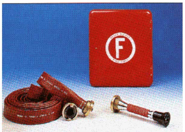
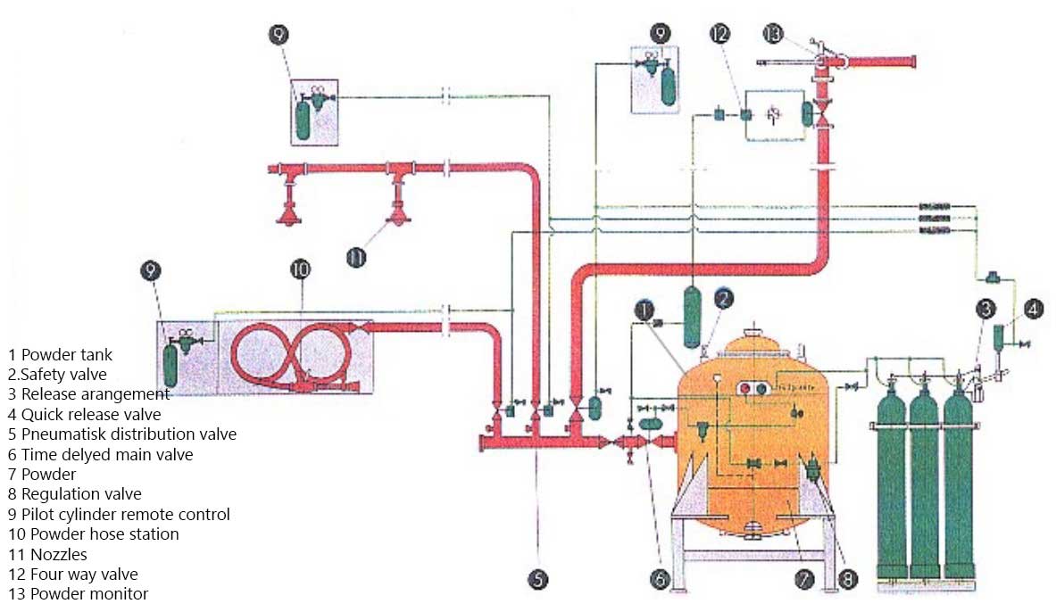
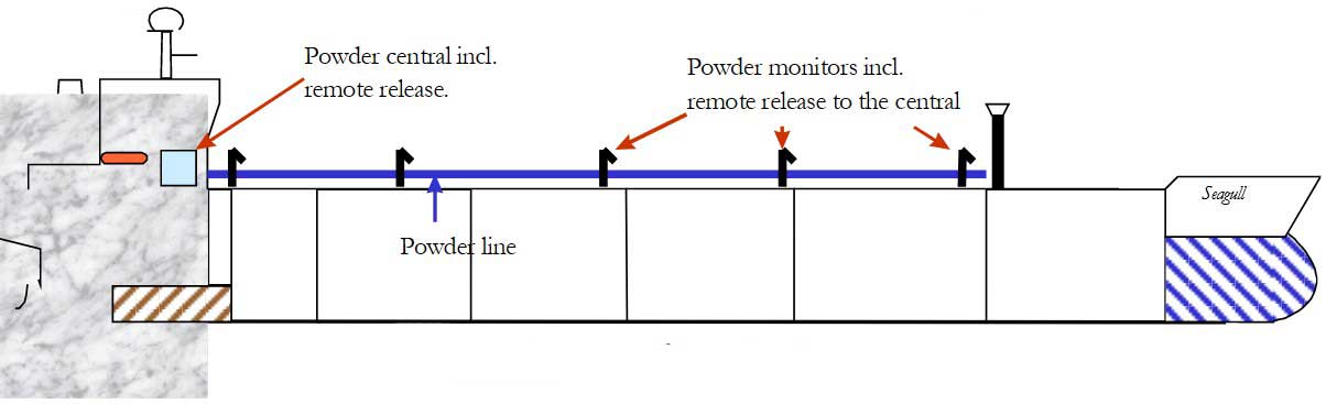
Powder is elected as extinguishing remedy on the tank deck of gas carriers and chemical tankers. A number of minor stationary powder aggregates can be placed on deck or a powder central unit with pipes forward to a number of powder monitors and hose stations on deck. One or several powder containers are placed with a capacity calculated for the specific vessel with accompanying pressure bottles in the powder central unit.
The plant can be released from each powder post by opening the valve of the releasing bottle. The gas is lead into tubes to the releasing mechanism of the pressure bottles in the powder central unit. It opens the valve of the powder tube that proceeds to the powder post being released. Several posts can be utilised at the same time, but each post must be triggered in the same way.
Stationary dry powder systems are normally delivered with powder (NaHCO3 – Natrium hydrogen carbonate or KHCO3 – calcium hydrogen carbonate) for extinguishing fire in class B or E.
That is all types of liquid like:
- petrol;
- alcohol;
- acetone;
- oil;
- painting etc.
and different types of gases like:
- methanol;
- methane;
- butane;
- propane etc.
Dry powder systems utilise N2 (Nitrogen) or CO2 (carbon dioxide) as propellant gas. The gas is kept in pressure cylinders. A gas pressure regulator reduces N2 – gas or CO2 – gas (200 kg/cm2) to 20 kg/cm2 before it goes via the riser in to the powder aggregate. The riser’s gas taps are very important, as the powder together with the propellant gas must be able to “float” as a liquid through the pipe system and the powder jet. The stationary powder post (monitor) should have a capacity of at least 10 kg/second.
Manual equipment, “hand hoses”, should have a capacity of at least 3,5 kg/second, but not too large for one man to operate. The length of a hand hose should not exceed 33 m. It is very important that the hose is pulled out to its full length before setting the pressure. The extension should be at a minimum of 10 metres for both stationary and hand based equipment. The plant’s powder capacity should be of the size that utilises all posts. The delivery of powder should progress at a minimum of 45 seconds.
Below is an example of this with the following data:
| Stationary: | (4 pcs. x min.10kg./s x min. in 45s) | = 1 800 |
| Hand based: | (4 pcs. x min.3,5kg./s x min. in 45s) | = 630 |
| Minimum powder capacity: | 2430 kg. | |
Technical description
The powder type NaHCO3 and KHCO3 has an extinguishing effect based on a reaction inhibitor along with some cooling of the fuel surface and the gas face. Powder is not electrically conductive in dry conditions. To avoid humidity in the powder, a water-repellent material is added usually silicon.
Dry chemical systems consist of a mechanical part that includes a powder aggregate with valves, release mechanism, pipe system and jets. Everyone must memorise maintenance routines and test routines, based on the plant on the specific vessel. (This is part of the fire drill onboard).
Water – spray system
Gas and chemical carriers
In addition, certain ship types should be equipped with a “water-spray system”, as an object for a cooling, fire preventive and crew protective effect. We refer here to the IGC-code, chapter 11, point 11.3.1, what areas the plant should cover. The plant onboard the specific ship is designed according to this.
The system should have the capacity to cover the designated area with at least 10 ltr./m2 per minute on horizontal surfaces, and 4 ltr./m2 per minute on vertical surfaces.
If parts of the line are damaged, shut-off valves must exist on the main line so that the line can still be utilised. This is operable by shutting off the line to the damaged area. The alternative is that the system is devisable into several sections that can be operated independent of each other. The delivery pumps should have such a capacity that they can deliver simultaneously with full capacity to the whole plant. The plant should contain a material that is resistant to corrosion.
There has to be a possibility of remote start of the water delivery pumps, plus remote control of the plants shut valves from a place outside the cargo area. We recommend studying the plant on your vessel, how it is operated, where the remote control is, plus the inclusion of this in the fire drill executed onboard.
Foam in general
A system consisting of gas or air bubbles bound in a water coating (membrane), is called foam. Constant foam is when the wall/membrane consists of a constant material, such as pumice stone, gas concrete and foam rubber are examples of constant foam. When the wall has a coating, we are talking about floating foam, such as soapsuds. Different types of floating foams are used for fire extinguishing. On new gas and chemical carriers we also find foam utilised for fire extinguishing.
Producing foam
In order to produce foam that will extinguish fire, you need:
- water;
- a frothing material that dissolves in water in anatomised condition;
- and a non-flammable gas mixed with the solvent.
The foam is shaped when gas/air is mixed into the foam/frothing liquid and into the water by help of mechanical equipment. The result is mechanic foam.
Mechanical foam
Different types of pumps, sprinklers and foam pipes are used. The foam liquid is dissolved (or emulsified) in the water. After this, the air is mixed in by mechanical means. Normal equipment produces bubbles, which have a diameter of 0,1 mm to 1,5 mm.
Extinguish effect
Foam has a suffocating effect and acts as a cooling extinguishing agent. The suffocating or the cooling effect can be more or less the dominating effect, but depends on what material is burning and what sort of foam is used. By extinguishing a burning liquid with a surface temperature higher than +100 °C, the cooling effect is the dominating force. This is caused by evaporation of the liquid that penetrates into the surface’s layer of the burning material as the foam collapses.
By extinguishing fire when the temperature in the surface is below +100 °C, the extinguishing effect is connected with the heat-insulating foam and, above all, a differentiation effect. When the foam cover has spread outward across the liquid’s surface, the heat rays from other, still burning parts of the liquid surface, is not able to penetrate through the area covered with foam. Therefore, combustible gases are no longer formed, evaporation ceases and the fire die out.
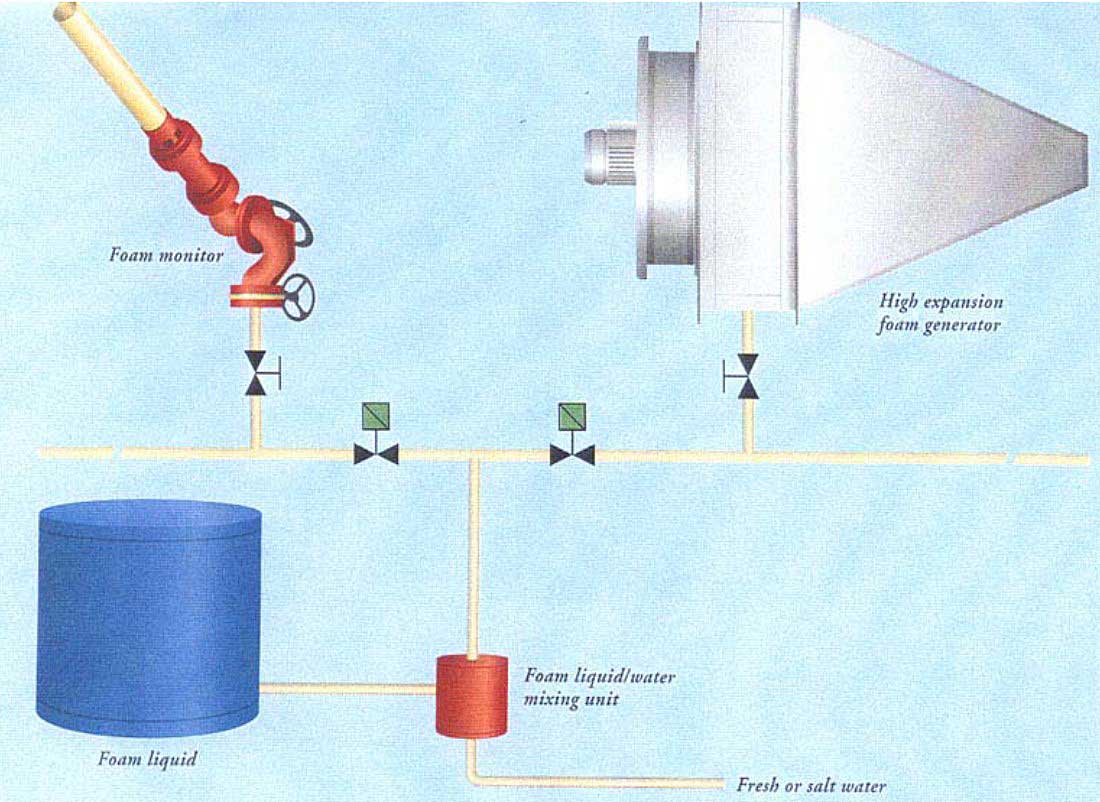
Foam plant
Foam is chosen as the main extinguishing agent for the tank area. A foam plant consists of a foam central unit with a foam tank, foam pump that is also connected to an emergency generator, distribution manifold, foam jets, automatic valves, and a pipe system connected to fixed monitors on the tank deck. The capacity of the plant should be big enough that the whole tank area could be covered with foam. If the vessel has an inert gas plant, the foam capacity must have a volume that can deliver foam for a minimum of 20 minutes. The demand is at a minimum of 30 minutes if the ship is not equipped with inert gas plant.
The main foam line from the foam central unit to the monitors should contain shut-off valves within determined requirements, in order to bind the line in case of damage. The foam line going to each monitor has a delivery valve installed to supply foam. The valve can also be used to regulate the amount of foam supplied in order to achieve the right mixture condition between foam and water.
A foam jet pipe is attached to the monitors. Study the plant installed on your vessel, and understand how this plan is operated. This equipment (the foam plant) is mandatory for oil tankers.
Mobile foam equipment is also available on many ships, gas and chemical carriers also. This consists of:
- a fire hose with a foam nozzle unit;
- small foam containers (20 litre);
- a foam ejector;
- a small hose for the transmission of foam from a foam container to a foam hosepipe;
- and protection equipment.
This equipment is prepared for use with fire hoses and a foam nozzle unit connected to the fire line. A foam ejector with a tap for supplying foam liquid is installed between the fire hose and foam nozzle unit. Water pressure is established, foam liquid is sucked (ejector function) from the foam container via hose connection between the foam container and ejector.
Pollution prevention
It is the responsibility of the master or those in charge of transfer operations involving cargo or bunkers to know the applicable pollution prevention regulations and to ensure that they are not violated. Exercises should be held to train personnel in accordance with the Shipboard Oil Pollution Emergency Response Plan, and recorded.
There is a danger of violating pollution prevention regulations if ballast taken on in polluted waters is discharged in another port. If ballast has to be taken on in polluted areas, it may be necessary to exchange it for clean ballast when in deep water on passage. Some terminals have specific requirements in this respect, and the master should ensure that they are observed.
Pollution in general and its effect on Ecology
Note that pollution is usually related to human activity. Phenomena, such as radiation due to natural radioactivity in the earth, volcano eruptions and the like, are not usually considered as pollution. They exist, however, in areas where the environment is burdened. This is nature’s own way to balance and renew itself.
Any pollution has a main source and a receiver. The main receivers are:
- air;
- sea;
- and soil.
The most effective way of spreading pollution is through air. But eventually the pollution always falls to the ground and into the sea. The earth is most resistant to pollution as a receiver, but the problems appear because this pollution almost without restrictions has free flow to pollute sea and waters.
Compare the human body with its own immune system to the environmental system (Eco-system), and you will find that all basic “building blocks” are linked together in some way or another with the same influence and with the same purpose. Every part is equally important in obtaining the ability to function as a whole unit.
Definition of pollution
Substances and materials spread through air – sea – and soil that cause damage and malfunction due to human activity.
Many factors contribute to pollution, such as the chemical, physiological or biological characteristics. Life on earth is dependent on solar energy. Plants turn solar energy, water and carbon into plant tissues. This is called the first tropic level. The herbivores (vegetable-only eating animals) cannot exploit solar light directly in their growth or tissue change. Herbivores use the plants to produce tissue. This is called the second tropic level.
The energy loss caused by transmission from the first level to the second level is calculated to be at approximately 90 %. An even greater loss appears at the next level, which is the third tropic level. This level includes the humans and the animals, which survive by eating animal meat. The demolishing link in this process is the carrion eaters and small organisms, which demolish dead plants and animal materials into simple organic and inorganic compounds, which the plants need to grow.

An Ecology System appears as a result of developing and adapting to each other as a species in nature throughout millions of years. Accurate balance and stability is obtained and smoothly functioning. This system is an everlasting process and is continuous throughout time and space.
An Ecology System can endure huge changes and variations in nature, but faced with artificial factors and synthetic substances spread by human actions, important parts (areas) in this process can be demolished. The reason is simply that no natural mechanism exists to keep the process active and in balance. In numerous cases, these unwanted non-natural substances are spread throughout the nature process creating disharmony and malfunctions both geographically and ecologically.
Pollution of air and sea and the influence of ship trade
Burning sulphurous fossil fuel forms sulphur-dioxides and compounds of this gas. The gas responds to air and transforms into sulphur acid. Nitrogen oxides are also formed by combustion of fossil fuel, and release nitrogen mono oxides, which again transforms into nitric acid and nitrogen oxides.
Carbon mono oxides formed by uncompleted consumption of organic material can further react to air and transform into carbon dioxide. Further, a number of gases are released with the gas freeing of cargo tanks and cooling plant. These are CFC – gases (chlorous fluor carbons). Carbon dioxide and CFC – gases function as a glass roof in a hothouse, the heat radiation from the sun is easily received and is harder to let go. This is the hothouse effect in a nutshell. Sulphur and nitrogen oxides in outlets (pollution) cause huge destruction of soil and sea. The consequences of this are recognised in areas where the forest is dead and fishing lakes are empty.
OPA90 The American “Oil Pollution Act of 1990”
In USA, the accidents involving “The Exxon Valdez” and “Mega Borg” were in focus and were well covered by the media and press, which influenced public opinion. This resulted in the OPA90. The media distributed pictures of the rich animal life and the magnificent coastline in Alaska covered with oil and showing the suffering of dying seals and seabirds.
This presentation made a strong impression, which made the U.S. Congress realise that the existing International Conventions had to be reviewed and bettered, in order to protect and take care of the American interests. American lawyers developed the OPA90 and the Congress supported the proposed Act.
The Main Items In OPA90
- The threat of unlimited responsibility.
- Demand of double hull.
- Direct access to the means in P & I – Companies, in case of indemnity due to accidents.
- Higher graded demands meant for the crew regarding narcotics and alcohol testing.
- Use of pilot in sensitive waters.
Entering American waters OPA requires drill (training) according to OPA90 regulations. The drill (training) should be logged and reported due to the ship owners/operators policy. OPA90 regulations are in force for all kind of ships.
MARPOL 73/78
-MARPOL-73, which is The International Convention about preventing Marine Pollution. The Convention consists of 20 articles, 2 Protocols and 5 Enclosures.
The 5 Enclosures are as follows:
- Enclosure I – Oils.
- Enclosure II – Chemicals.
- Enclosure III – Damaging elements in wrapped form, barrels, tanks, containers and so on.
- Enclosure IV – Sewage.
- Enclosure V – Garbage
Personal safety equipment
The minimum requirements for lifesaving equipment on board all ships are laid down by national and international regulations. All equipment should be inspected regularly and kept ready for immediate use in a clearly marked and accessible place. Practical demonstrations, training and drills should be regularly undertaken so that personnel become experienced in use of all safety equipment and know the location of each item.
Breathing apparatus
As previously indicated, it is always preferable to achieve a gas-free condition in a tank or enclosed space prior to entry by personnel. Where this is not possible, entry into tanks should only be permitted in exceptional circumstances and when there is no practical alternative, in which case, breathing apparatus (and if necessary, protective clothing) must be worn. There are four types of respiratory protection:
- Short duration breathing apparatus.
- Fresh air respirators.
- Compressed air breathing apparatus.
- Canister filter respirators.
Each type is described in the following sections.
Short-duration breathing apparatus
Short-duration breathing apparatus consists of a small compressed air cylinder and a polythene hood, which may be rapidly placed over the head. Their duration is limited to about 15 minutes of comparatively non-exertive effort and the sets must be used only for emergency escape purposes. Depending on the cargoes specified on the ship’s Certificate of Fitness, short-duration breathing apparatus may be provided in accommodation spaces for each crewmember.
Such equipment may also be supplied for inspections of gas-free enclosed spaces, as an aid in case a hazardous atmosphere is encountered, although, in cases of known danger, it is recommended that compressed air breathing apparatus be worn.
Fresh air respirators
Fresh air respirators consist of a helmet or facemask linked by a flexible hose (maximum length 40 metres) through which air is supplied by a manual bellows or rotary blower. The equipment is simple to operate and maintain and its operational duration is limited only by the stamina of the bellows or blower operators. However, movement of the user is limited by the weight and length of hose and great care must be taken to ensure that the hose does not become trapped or kinked.
Users of such equipment should always wear a safety line for communication and rescue. While this respirator has been largely superseded by the self-contained or airline compressed air breathing apparatus, it will be found on many ships as a backup to that equipment.
Compressed air breathing apparatus
Compressed air breathing apparatus may be adapted into two forms. It may be the self-contained type (SCBA) or the airline version (ALBA). In the self-contained (SCBA) version, the wearer carries air for breathing in a compressed air cylinder at an initial pressure of up to 300 bars. The pressure is reduced at the outlet to about 5 bars and fed to the facemask through a demand valve. This provides a slight positive pressure within the mask. The working duration of the equipment depends upon the capacity of the air cylinder and respiratory demand. A pressure gauge and an alarm are provided to warn of low air supply pressure.
A typical set, providing approximately 30 minutes operation with physical exertion, may weigh about 13 kg and the bulk of the cylinder on the back of the wearer imposes some restriction on manoeuvrability in confined spaces. When properly adjusted, the SCBA is simple and automatic in operation. However, maintenance requires care and skill. To ensure serviceability, all such breathing sets should be checked monthly and used during exercises. This should be done using special exercise air cylinders in order to keep the operational cylinders always fully charged or, alternatively, an air compressor may be used for immediate refilling.
Although demand valves are designed to maintain a slight positive pressure within the facemask, it should not be assumed that this feature would prevent a contaminated atmosphere leaking into an ill-fitting mask. It is essential that, before entry into a dangerous space, the air tightness of the mask on the wearer’s face be thoroughly checked in accordance with the manufacturer’s instructions.
Tests have shown that it is virtually impossible to ensure continued leak tightness in operational conditions on a bearded face.
Most compressed air breathing sets may be used in the airline version (ALBA) whereby the compressed air cylinder and a pressure reducing valve are placed outside the contaminated atmosphere and connected to the face mask and demand valve by a trailed air hose. At the expense of decreased range and the need for extra care in guiding the trailing air hose, the wearer is relieved of the bulk of the air cylinder. Also, operational duration may be extended by the use of larger air cylinders or special cylinder changeover arrangements.
Canister filter respirators versus SCBA
Canister filter respirators consist of a mask, which has a replaceable canister filter attached. In this type of equipment, the normal breathing of the wearer draws in contaminated air and toxic elements are filtered out. They are simple to operate and maintain, can be put on quickly and are used as personal protection for emergency escape purposes on ships certified for carrying toxic cargoes. They are, however, only suitable for relatively low concentrations of toxic gas. Once used, there is no simple means of assessing the remaining capacity of the filter.
Filter materials are specific to a limited range of gases and, of course, the respirator gives no protection in atmospheres of reduced oxygen content. For these reasons, the requirements of the Gas Codes for emergency escape protection is now almost exclusively met by lightweight self-contained breathing apparatus.
Canister filter respirators are not suitable for use in atmospheres where theoxygen content is insufficient to support life.
Training
Good training is essential in the use of this life-saving appliance. Specially marked cylinders should be used for training to ensure that in an emergency, only fully charged units are used. Cylinder pressures should be regularly checked and low-pressure cylinders should be recharged promptly.
Protective clothing
In addition to breathing apparatus, full protective clothing should be worn when entering an area where contact with cargo is a possibility. Types of protective clothing vary from those providing protection against liquid splashes to a full positive pressure gas-tight suit which will normally incorporate:
- helmet;
- gloves;
- boots.
Such clothing should also be resistant to low temperatures and solvents.
It is particularly important to wear full protective clothing when entering an enclosed space which has contained toxic gas such as:
- ammonia;
- chlorine;
- ethylene oxide;
- propylene oxide;
- vinyl chloride or butadiene.
For certain cargoes, the Gas Codes require the use of suitable eye protection.
Fire fighter equipment
The requirement onboard oil tankers, as well as onboard gas tankers less than 5 000 m3, are 4 sets of fire fighter equipment. Onboard gas carriers of more than 5 000 m3, a minimum of 5 sets of fire fighter equipment is required. Each set consists of:
- One breathing apparatus (BA) with an air capacity of minimum 1200 litres.
- Protection suit including boots and gloves.
- Fire resistance safety line with belt.
- Safety lamp.
- Fireman’s axe.
The equipment is specified in SOLAS, chapter 11-2, rule 17. National, and classification companies requirements may come in addition. This is of course considered for each vessel and the equipment is at all times in accordance to existing requirement and rules.
Fire stations
The fire stations are marked on the safety plan, and also the content of all required equipment at the stations. In addition to mentioned firefighting equipment, the content must include personal protective equipment, fire hoses, jet nozzles that can switched from jet to fog dispersement, keys to hose coupling and an extra fire axe.
Other equipment included is an electrical drill with 5/8” drill steel together with an extension cord. It is smart to obtain a smaller drill steel to drill a pilot hole, if this is a matter of necessity. A portable oxyacetylene torch that renders it possible to make a quick carving of a manhole or other openings to ease access is also included. This equipment is marked on the safety plan, where it is placed onboard and at the right number according to type and size of vessel.
Everyone is encouraged to know the seriousness of exercises onboard, being prepared in a realistic and objective way can be, as a matter of fact, very interesting and informative. Anxiety is relieved because confidence leads to safety.

Accommodation
Regulations require that superstructures are designed with certain portholes fixed shut and openings positioned to minimise the possibility of vapour entry. These design features should not be modified in any way. All doors, portholes and other openings to gas-safe spaces should be kept closed during cargo operations.
Doors should be clearly marked if they have to be kept permanently closed in port, but in no circumstances should they be locked. Mechanical ventilation should be stopped and air conditioning units operated on closed cycle or stopped if there is any possibility of vapour being drawn into the accommodation.
It's remarkable sight which I've ever seen !!!