Welcome to the website where you can find answers for the CES test on the subject «Electrical Electronic & Control». This site will help you as a marine specialist improve your knowledge with the help of open information, where you can find questions as well as answers for them. CES based on practical information and marine specialists experience.
CES tests developed for evaluating seaman basic knowledge by Seagull Company (rebranded as «OTG»), is an evaluating online-tool, used for revealing any professional preparation needed in specific fields of knowledge, defined by STCW.
Version: 6.0.10.
Test type: STCW.
Department: Engine.
Level: Management.
Module: Electrical Electronic & Control.
CES tests have proven themselves as good tools for the selection and recruitment process, as well as advancing the level of knowledge of the current officers and crew. Ocean Technologies Group use various subjects for question creation, which includes:
Crowd and Crisis Management;
Integrated Navigation System (INS);
Ballast water management;
Handling and Stowage;
Vessel operation management and safety;
Marine engineering;
Maintenance and repair, etc.
«Electronics» subject includes theoretical and practical information about safety working with electrical equipment. Knowledge of this information directly shows employee’s competence who holds a relevant post on a vessel. The role of a worker in the machine department involves providing equipment support and requires a solid technical understanding of the equipment’s operation and components. It is important for them to be well-versed in the fundamental principles of each device’s function, as well as capable of diagnosing and resolving malfunctions. To effectively perform tasks related to servicing and repair, it is crucial for the employee to stay up-to-date with the latest updates and advancements in equipment technology. Additionally, having basic communication and collaboration skills is essential for interacting with team members and clients, particularly when providing assistance and consultations.
This page contains answers to Seagull CES (Crew Evaluation System) test about Electrical Electronic & Control, and serve as a database of questions and answers, using which seafarer can prepare to exams for getting certificate of competence, or just to challenge yourself with knowledge in this theme.
Special thanks to JSEC and Mr Animesh from our Telegram channel, without you this test would not exist.
Choose the regime, in which you want to pass CES test:
Training
Exam
Wild mode
* Some questions may have more than 1 correct answer.
“CES test” finished! Your result:
Correct answers:
⭐
Youve answered 5 questions
Get Premium to unlock the full version of this test, plus 1,000+ other practice exams.
Seafarers who prepare with Premium for just 20 minutes a day are 82% more likely to land their dream job.
Code: RTXB A 5 V DC source has an internal impedance of 0,2 ohms. When a load of 2,3 ohms is applied what voltage will be measured at the source terminals?
4,6 V.
5,2 V.
4,8 V.
5,0 V.
Code: ACJL A triac is used to provide temperature control of an oven. The galley complain that the oven only reaches approximately 50 % of demanded temperature. Which of the following is a likely cause?
One of the main switching elements in the triac has failed.
The voltage supply to the oven controller is reduced by about 50 %.
Connection between the demand knob and the triac gate terminal has gone open circuit.
The triac has completely failed.
Which of the following measures is to be taken when working with batteries?
Recharge batteries immediately after discharge.
Install alkaline and lead-acid batteries in the same compartment.
Add new acid electrolyte to batteries that are in use.
Keep the batteries in discharged state.
Which of the following is an application of a piezoelectric sensor?
Accelerometer.
Tachometer.
Thermocouple.
I don't know.
What is the minimum starting requirement of an emergency generator?
2 separate starting devices each with stored energy capable for at least 3 consecutive starts.
3 separate starting devices each with stored energy capable for at least 3 consecutive starts.
1 set of starting device with stored energy capable for at least 3 consecutive starts.
2 separate starting devices each with stored energy capable for at least 4 consecutive starts.
Code: RPHF When considering instrumentation systems, what is the meaning of the expression "dead-band"?
The controller will not react to a process change in this range.
The controller will is not respond to adjustment of set-point.
The controller will enter "sleep mode".
It will take some time before the controller will react to a change.
Which of the following is the minimum acceptable value of insulation resistance for High Voltage equipment?
100 M Ohms.
1 G Ohms.
1 M Ohms.
100 k Ohms.
In tanker operations, there will be some areas and zones where flammable or explosive vapour, gas or dust may be expected. Such areas are classified as hazardous. What is meant by hazardous area Zone 1?
Flammable mixture is not continuously present, but will be present during normal operations.
Flammable mixture would not normally be present or it would be present for a short period only.
Flammable mixture is not present at all times.
Flammable mixture is continuously present or present for long periods.
Code: BOKI Which of the following methods may a diode be tested by?
Use a Digital Multi-Meter set to measure ohms in forward and reverse directions.
Use a Digital Multi-Meter set to check forward voltage and reverse current blocking.
Use an insulation resistance tester (Megger).
Connect to low ohms resistance tester.
Code: PDRS When performing electrical testing of a three phase motor, insulation resistance measurements may be influenced by which of the following?
Temperature, humidity and surface contamination.
Humidity, frequency and dampness.
Temperature, pressure and dampness.
Humidity, pressure and surface contamination.
Flow irregularities in pipes are not caused by:
Straight pipe.
Throttling valve.
Elbow pipe.
Restrictive valve.
Which of the following is not a mode of a closed loop control?
Manual.
PID.
Modulation.
On-off.
A Multimeter is not suitable to measure:
Power.
Current.
Resistance.
Voltage.
Code: OKWA Continuity testing of a delta connected three phase induction motor yields the following results; U1-V1 = 4 ohms, V1-W1 = 4 ohms, W1-U1 = 4 ohms. What is the value of continuity resistance for each winding ie. U1-U2?
6 ohms.
2 ohms.
4 ohms.
12 ohms.
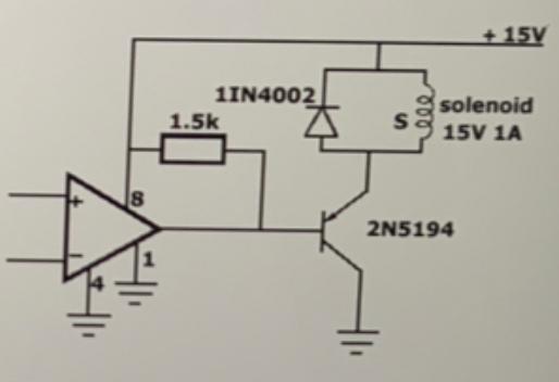
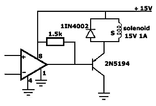
Code: KKHF Which of the following functions does the diode shown here perform?
Return inductive current to supply at switch off.
Allow Op Amp to top up +15 V rail.
Reference the transistor to +15 V.
Provide an overload route for transistor current.
Which of the following is an application of an capacitive sensor?
Barometer.
Tachometer.
Proximity sensor.
Piezoelectric sensor.
Code: FEYS Some ships generate electrical power at 440 Volts, but then step up this voltage to supply specific electrical equipment. One common example, may be to feed a large bow thruster. Why is this done?
A large bow thruster will draw very large currents at low voltage. Being typically remote from the generator, significant voltage drops would occur at low voltage.
The shipyard could not purchase High Voltage generating plant at the time of manufacture, so they used what was available at the time.
The overall ship's electrical load does not justify High Voltage generating plant. This method allows more power to be delivered to the bow thruster at low running cost.
Manufacturers can supply High Voltage bow thrusters at less cost, and the power factor is improved.
Code: BFGX In an automatic temperature control system, operating with a PID controller which of the following settings or parameter adjustments may result in system oscillation?
Gain too high.
Gain too low.
Temperature change.
Too short D-time.
What are the main elements for Process Control?
Process, Sensor, Final control element and Controller.
Sensor, Modulation, Controller, Process.
Sensor, Controller, Noise, Final Control Element.
Resistor, Capacitor, Battery, Load.
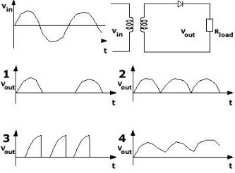
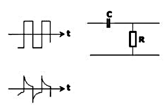
Following shows circuitry of a peak detector. What is the output voltage curve, Vo if Vi is a sinusoidal input curve?
Vo will be the same sinusoidal curve but at a lesser amplitude.
Vo will peak when Vi is at the maximum, remain constant and fall to zero when Vi becomes negative.
Vo will spike when Vi is at the maximum/minimum point of the sinusoidal curve; zero everywhere else.
Vo will peak at a level less than Vi maximum voltage and remain constant throughout.
Code: THJL When selecting switchgear to work with High Voltage it is important to use an appropriate arc quenching medium. What is meant by arc quenching medium?
The gas, liquid or vapour which will minimise creation of an electric arc as contacts open.
Equipment which communicates information about the arcing.
The way in which the contacts separate as the switchgear operates.
A material which assists a welding process.
Code: PEBH A 250 V contactor has been fitted to a 220 V supply. Which of the following symptoms might be observed?
Contactor chattering (vibrating).
Contactor overheating.
Contactor wont operate.
Contactor constantly on.
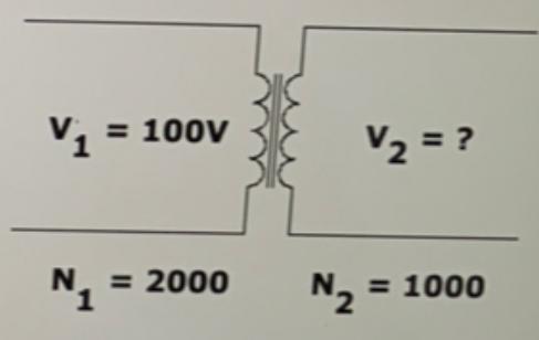
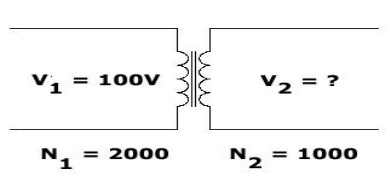
Code: SRBP The circuit shows a transformer with two windings, N (1) = 2 000 and N (2) = 1 000 turns, on a common magnetic circuit. Assume that there are no energy losses in the transformer itself. Calculate the output voltage V (2) when the input voltage is V (1) = 100 Volt.
V (2) = 50 V.
V (2) = 400 V.
V (2) = 200 V.
V (2) = 10 V.
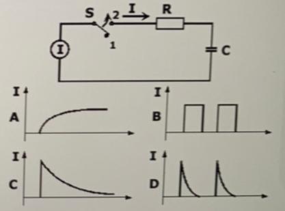
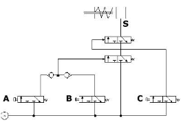
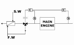
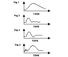
This circuit consists of a current source I, a change-over switch S, a resistor R and a capacitor C. The current/time figures 1 to 4 show possible changes in the current I when the switch S is suddenly shifted from position 1 to 2 at time t = 0. Which diagram is correct?
Figure A.
Figure B.
Figure C.
Figure D.
Code: AOML Which cell voltage is required to trickle charge a lead acid battery?
2,15 V.
1,2 V.
2,5 V.
2,0 V.
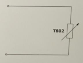
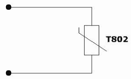
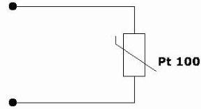
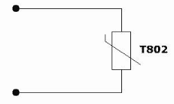
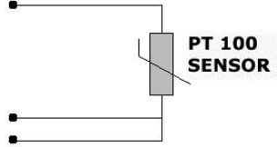
Code: VATG When the cable length exceeds approx. 10 meters we normally have to in case of a Pt 100, in some way compensate for the cable resistance. Do we also have to do this if we choose to use a T802 temperature sensor?
No.
Yes.
Depends on temperature to be measured.
Not applicable.
Code: TEOA High Voltage systems rely on the installed protective equipment being able to interrupt any fault in the system. Throughout the system, the fault level has been calculated, and under no circumstances must the system be modified to exceed this fault level. What is meant by fault level?
The amount of apparent power, that would be drawn from the generating plant, when a short circuit occurs at the bus bars.
The amount of apparent power that could flow into any fault at any.
The current level flowing into a symmetrical short circuit fault between all three phases.
The current level flowing into a dead short to earth at any point on the ship, directly from the High Voltage system.
Code: BGNJ The continuity resistance of a 100 m long × 25 sq. mm cable (rated at 100 A) is to be checked. Which of the following results would you anticipate?
Between 0,1 and 1,0 Ohm.
Between 0,1 Micro Ohm and 1,0 Micro Ohm.
Between 0,1 and 1,0 M Ohm.
Greater than 1 M Ohms.
Code: XQSO When starting three phase induction motors which of the following starting methods will immediately apply rated voltage to the machine?
Direct on Line.
Star Delta.
Auto - transformer.
Soft starter.
Code: HQPE Continuity testing of a delta connected three phase induction motor yields the following results; U-V = 3 Ohms, V-W = 3 Ohms, W-U = 6 Ohms. Which of the following is the likely condition?
Open circuit winding between W and U.
Short circuit winding between W and U.
Partial fault between W and U.
Short circuit between V and Earth.
Code: RGBR What is the advantage of a transmitter with a narrow measurement range?
Better linearity and increased accuracy.
Easy installation.
Do not need any calibration.
Lower purchase cost.
Code: UGPX How can a lead-acid type battery be checked to confirm if it is fully charged or not?
Measure the relative density (specific gravity) of the electrolyte.
Measure the level of the electrolyte.
Measure the battery voltage.
Measure the temperature of the electrolyte.
When polarity of the incoming power line is reversed, what happens to the DC motor?
Motor rotates in the reverse direction.
Motor explodes.
Motor still rotates in the same direction.
Motor stalls.
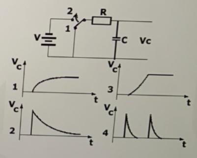
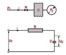
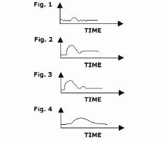
Code: BXUA This circuit consists of a voltage source V, a change-over switch S, a resistor R and a capacitor C. The voltage/time figures 1 to 4 show changes in the voltage V(C) when the switch S is suddenly shifted from position 1 to 2 at time t = 0. Only one of the diagrams is correct. Which?
Figure 1.
Figure 2.
Figure 3.
Figure 4.
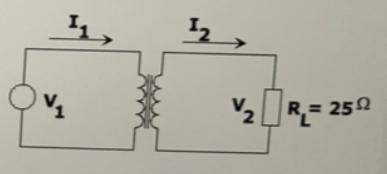
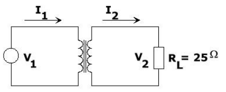
Code: NCNE This figure shows a transformer, with two windings, N(1) = 2 000 and N(2) = 1 000 turns, on a common magnetic circuit. Assume that there is no energy loss in the transformer itself. Calculate the current l(2) when the current l(1) = 2 A.
l(2) = 4 A.
l(2) = 2 A.
l(2) = 1 A.
l(2) = 8 A.
Code: EKVD What should be the healthy continuity resistance of a 220 V, 2,2 kW, 10 A heating element, when checked near to it's rated operating temperature?
22 Ohms.
10 Ohms.
0,1 Ohms.
220 Ohms.
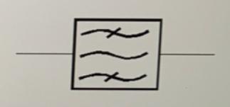
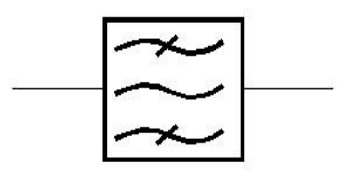
Code: UDFB Which electronic component or system is this graphical symbol illustrating?
Bandpass filter.
Transformer with ferromagnetic core.
Electric heater.
3-phase sine-wave generator.
Code: GNXL Can a ZENER BARRIER be installed in a hazardous area?
No, as only the output from the barrier is intrinsically safe this is not allowed.
Yes, that's what the zener barrier is made for.
Only if properly marked for such installation.
Only in equipment operating on very low voltage.
Code: DBRX When there is a need to interrupt current flow in a high voltage system it may be very difficult to quench the electrical arc which is generated at the circuit breaker contacts. Which of the following arcing media is commonly found in high voltage marine switchgear?
Vacuum.
Water.
Air.
Oil.
What is this?
A voltage transformer.
A zener barrier.
A current rectifier.
An isolation amplifier.
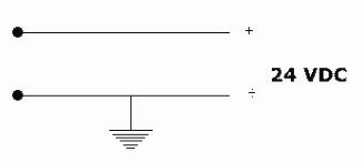
Which method is best for determining earth failure on a 24 VDC power supply?
Using a voltmeter across the supply terminals.
A lamp, (0-50 mA) and a mA-meter in series.
Connecting an oscilloscope to the output.
Measuring resistance with an ohmmeter.
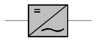
Which electronic component or system of components is this graphical symbol illustrating?
Rectifier.
Inverter.
Transformer.
Voltage regulator.
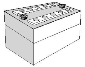
What kind of electrolyte is used for Nickel-iron batteries?
Sulfuric acid solution.
Solution of potassium hydroxide (KOH) and water.
Distilled water only.
Sodium chloride solution.
The maximum current that a 15 Volt, 3 Watt Zener diode can handle without damage is...
0,1 A.
0,2 A.
0,5 A.
3 A.
The instrument most widely used for testing of semiconductor diodes is...
Voltmeter.
Ohmmeter.
Oscilloscope.
Ammeter.
Which cell voltage will you supply for trickle charging of a lead acid battery?
1,8 V.
2,15 V.
2,5 V.
3,0 V.
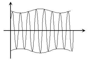
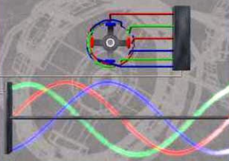
Radio frequency signals can carry information from one place to another if it is modulated. There are several ways to modulate a carrier. Which modulating method is illustrated here?
Frequency modulation (FM).
Amplitude modulation (AM).
Phase modulation (PM).
Pulse modulation.
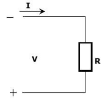
An important quantity which is useful in circuit analysis is known as conductance G (Siemens). Which of the formulas A to D expresses the conductance for this circuit?
G = V/I.
G = V × I.
G = I/R.
G = R × I.
When we are using a diode to convert AC to DC, it is usually referred to as a...
Inverter.
Voltage regulator.
Rectifier.
Amplifier.
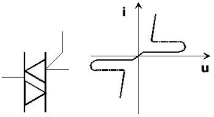
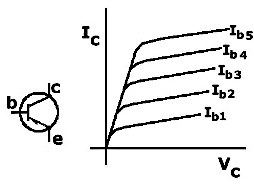
The figures show a graphical symbol for a particular electronic component and a typical working characteristic for the same component. Which component?
Diac.
SCR.
Triac.
MOSFET.
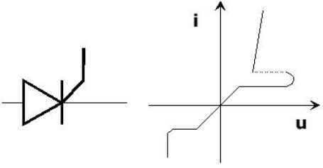
The figures show a graphical symbol for a particular electronic component and a typical working characteristic for the same component. Which component?
Triac.
Diac.
Silicon controlled rectifier (SCR).
MOSFET.
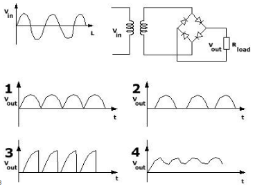
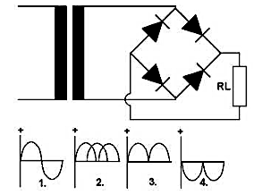
The circuit symbol is a widely used system for converting AC voltage to DC voltage. In this case the input voltage is a sine-wave. Which of the shown diagrams is correct for the output voltage V(out.)?
Figure 2.
Figure 3.
Figure 1.
Figure 4.
Which statement is correct with regards to power supply for equipment supplied through Zener-barriers?
The positive voltage must always be grounded.
The 0-voltage must always be grounded.
The negative voltage must always be grounded.
No voltage should be grounded.
What is the meaning of the abbreviation PCB?
Personal Control Bus.
Printed Circuit Board.
Power Control Box.
Primary Connection Board.
When data are to be transferred over telephone lines, we often utilize modem at each end. Which of the following adapter cards (parts) will you use for interfacing a modem to a computer?
Parallel adapter.
USB adapter.
Serial adapter.
Network interface card (NIC).
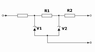
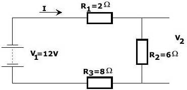
Use Kirchoff`s voltage law and Ohm`s law to calculate the voltage V(2) across the resistance R(2).
3,0 V.
5,0 V.
4,5 V.
6,0 V.
How can we check if a lead-acid type battery is fully charged or not?
Measure the battery voltage only.
Measure the specific gravity of the electrolyte.
Check the battery temperature.
Measure the battery current.
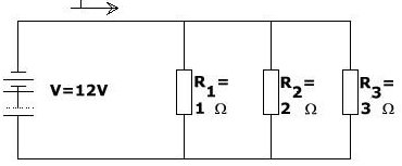
Use Kirchoff`s current law and Ohm`s law to calculate the value of the current I for this circuit.
18 A.
20 A.
22 A.
25 A.
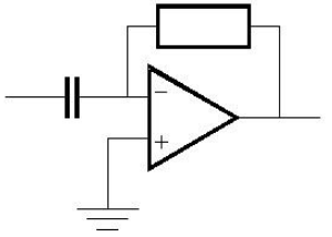
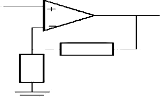
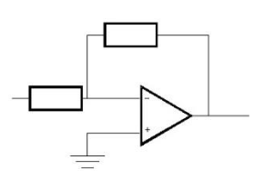
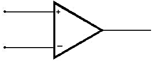
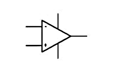
Which function is this operational amplifier circuit performing?
Integrator.
Amplifier.
Differentiator.
Comparator.
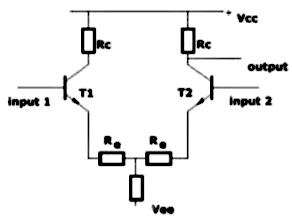
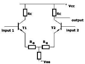
This amplifier circuit is a very common configuration used to amplify the difference in voltage between two input signals; in this case input 1 and 2. What is this amplifier called?
Operational amplifier.
Differential amplifier.
Instrumentation amplifier.
Buffer amplifier.
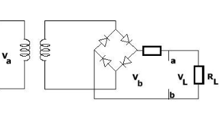
The circuit symbol is a full-wave bridge rectifier. Which electronic component will you connect between «a» and «b» in order to obtain reduced ripple voltage to the load RL?
Inductor.
Resistor.
Capacitor.
Zener diode.
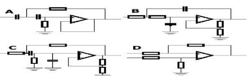
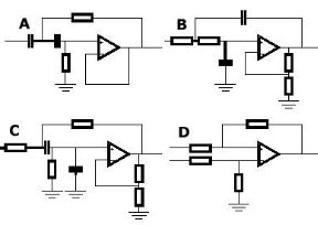
These circuits are all active filters. Which of the circuits is a high-pass filter?
Figure B.
Figure C.
Figure A.
Figure D.
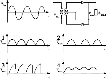
The circuit symbol is a widely used system for rectification of AC into DC. Which of the diagrams is the correct for the output voltage when the input voltage is sine-shaped as shown?
Figure 2.
Figure 3.
Figure 1.
Figure 4.
These circuits are all active filters. Which of the circuits is a band-pass filter?
Figure A.
Figure B.
Figure C.
Figure D.
Ordinary thyristors (SCR) must often be protected against reverse overvoltage transients because even over-voltages of extremely short duration can destroy them. These circuits have been given such over-voltage protection, but only one of them is correct. Which?
Figure 2.
Figure 3.
Figure 1.
Figure 4.
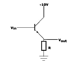
This is a typical emitter follower. What is the main benefit obtained by use of an emitter follower?
The output impedance is made much larger than the input impedance.
The voltage gain is significantly increased.
The input impedance is made much larger than the output impedance.
The current gain is reduced.
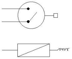
The circuit symbol is a driver for a solenoid (coil) of a solenoid valve S. What is the purpose of the diode IN 4002 connected in parallel to the solenoid S?
Limiting current through the solenoid.
Blocking inductive kick from the solenoid.
Amplifying the voltage across the solenoid.
Rectifying AC voltage applied to the solenoid.
The figures show a graphical symbol for a particular electronic component and a typical working characteristic for the same. Which component?
Diode.
Transistor.
Thyristor.
Triac.
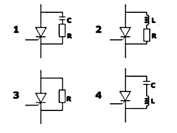
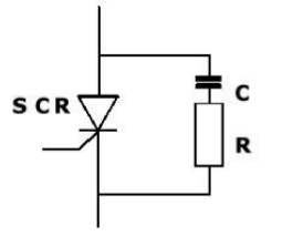
The figure shows a silicon controlled rectifier with a RC circuit connected in parallel. RC circuit is often used in such connection. For which purpose?
To increase the SCR triggering voltage.
To decrease the SCR holding current.
Protect the SCR against damage caused by high voltage spikes.
To improve SCR switching speed.
This figure is a transformer, with two windings, N(1) = 2 000 and N(2) = 1 000 turns, on a common magnetic circuit. Assume that there is no energy loss in the transformer itself. Calculate the current I(2) when the current I(1) = 2 A.
I(2) = 1 A.
I(2) = 2 A.
I(2) = 4 A.
I(2) = 0,5 A.
This circuit is a transformer with two windings, N(1) = 2 000 and N(2) = 1 000 turns, on a common magnetic circuit. Assume that there are no energy losses in the transformer itself. Calculate the output voltage V(2) when the input voltage is V(1) = 100 Volt.
V(2) = 200 V.
V(2) = 100 V.
V(2) = 50 V.
V(2) = 25 V.
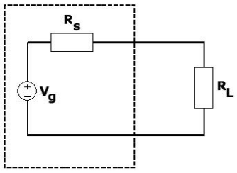
There are many applications in circuit theory where it is important to obtain the maximum possible power that a given source can deliver. This figure consists of a practical voltage source V(g) with internal resistance R(s). A resistance R(L) will maximize the power transmission from the source to R(L)?
R(L) = 0.
R(L) = 2R(s).
R(L) = R(s).
R(L) = R(s)/2.
What is digital signal?
A continuously varying signal over time.
A signal representing 0 = «low» and 1 = «High».
A signal that only changes frequency.
A signal with infinite amplitude levels.
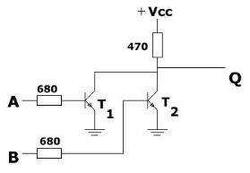
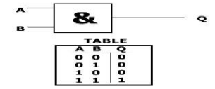
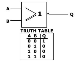
This circuit is a logic gate with two input signals, A and B, and one output signal Q. Which type of logic function is the gate giving?
AND gate.
OR gate.
NOR gate.
XOR gate.
Diodes are widely used in rectification, or the conversion of alternating current to direct current. This circuit symbol is such example. The input voltage V(in) is sine-wave AC. Which of the shown output voltages is correct for this circuit?
Figure 2.
Figure 3.
Figure 1.
Figure 4.
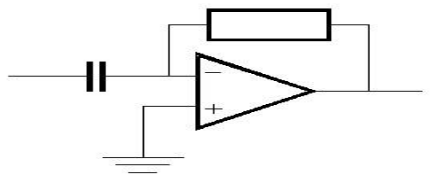
Which function is this operational amplifier circuit performing?
Inverting amplifier.
Voltage follower.
Non-inverting amplifier.
Comparator.
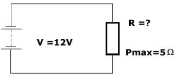
Choose the resistance R from the list A to D which allows highest possible current without exceeding 5W power consumption.
R = 10 ohm.
R = 50 ohm.
R = 25 ohm.
R = 100 ohm.
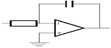
Which function is this operational amplifier circuit performing?
Differentiator.
Comparator.
Integrator.
Non-inverting amplifier.
Which function is this operational amplifier circuit performing?
Integrator.
Comparator.
Non-inverting amplifier.
Differentiator.
This graphical symbol is a logic gate. Which gate?
OR gate.
NAND gate.
AND gate.
XOR gate.
This graphical symbol is a logic gate. Which gate?
AND gate.
OR gate.
XOR gate.
NAND gate.
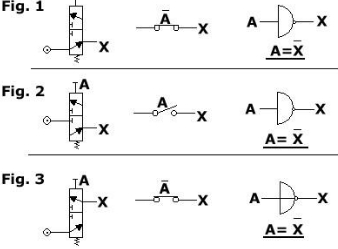
This graphical symbol is a logic gate. Which gate?
AND gate.
OR gate.
XOR gate.
NOR gate.
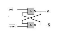
This circuit is a flip-flop. Which type?
Mono-stable flip-flop.
Bi-stable flip-flop.
Uni-stable flip-flop.
T flip-flop.
This is a parallel L-C circuit with curve showing frequency- impedance characteristics. Which of the formulas A to D will you utilize for determining the resonant frequency f?
f = 2π√(L*C).
f = 1/(2π L C).
fo = 1/(2√(L/C)).
f = L/C.
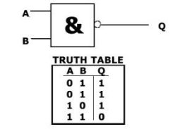
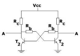
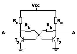
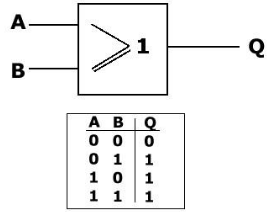
This circuit is a logic gate with two input signals, A and B, and one output signal Q. Which type of logic function is the gate giving?
AND gate.
NOR gate.
XOR gate.
OR gate.
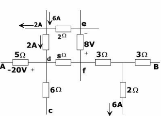
Find the value of the voltage drop from terminal A to terminal B in this circuit:
12 V.
24 V.
38 V.
50 V.
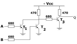
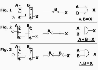
Which of the 3 alternatives given is correct for an AND-gate?
Figure 1.
Figure 2.
Figure 3.
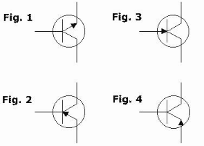
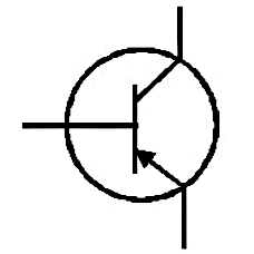
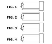
Which of the 4 alternatives shows a PNP transistor?
Figure 1.
Figure 2.
Figure 3.
Figure 4.
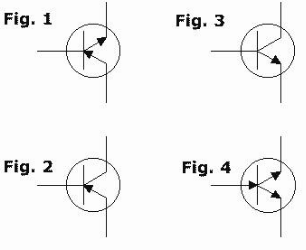
Which of the 4 alternatives shows a NPN transistor?
Figure 1.
Figure 2.
Figure 3.
Figure 4.
What do you understand with a computer`s POST system?
A series of tests run by the computer at power on.
A software update process for the operating system.
A method for cooling the CPU.
A network diagnostic tool.
The picture shows a commonly used 3,5 inches diskette type for storing data. What is the data storing capacity for such diskette?
720 KB.
1 MB.
1,44 MB.
2,88 MB.
The power supply to the hard disk of a personal computer consists normally of two voltages. Which?
3,3 V and 5 V.
5 V and 12 V.
12 V and 24 V.
1,8 V and 3,3 V.
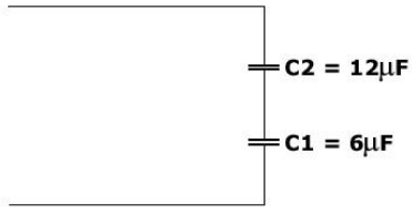
This circuit consists of two capacitors, C(1) = 6 and C(2) = 4. What is the total capacitance if connected in series?
6 F.
10 F.
C(S) = 4
2 F.
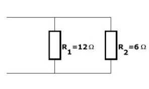
This circuit consists of two resistances, R(1) = 12 ohm and R(2) = 6 ohm, connected in parallel. Calculate the equivalent value R(S) of the two resistances.
2 ohm.
6 ohm.
R(S)= 4 ohm.
8 ohm.
Which function is this operational amplifier circuit performing?
Non-inverting amplifier.
Integrator.
Comparator.
Inverting amplifier.
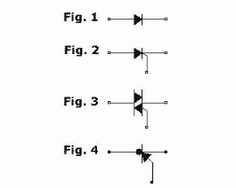
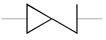
What is the symbol for a THYRISTOR?
Figure 1.
Figure 2.
Figure 3.
Figure 4.
Which of the 3 alternatives given is correct for a NOT-gate?
Figure 1.
Figure 2.
Figure 3.
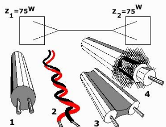
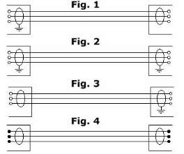
Transmission lines play a central role in radio frequency circuits, where they are used to pipe signals around from one place to another within a circuit, and often to an antenna system. General rules for such transmission line is that they must be «matched». Which of the cables below would you use to obtain a matched transmission between Z1 and Z2?
Figure 1.
Figure 2.
Figure 3.
Figure 4.
This graphical symbol is a logic gate. Which gate?
AND gate.
NOR gate.
XOR gate.
OR gate.
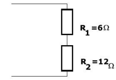
This circuit consists of two resistances, R1 = 6 ohm and R2 = 12 ohm, connected in series. Calculate the equivalent resistance R(S) of the two resistances.
R(S) = 6 ohm.
R(S) = 18 ohm.
R(S) = 12 ohm.
R(S) = 3 ohm.
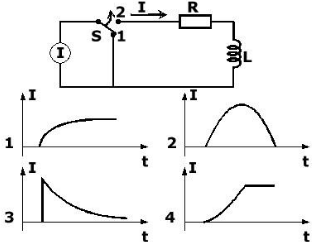
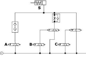
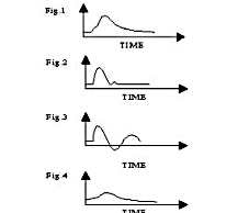
This circuit consists of a current source I, a change-over switch S, a resistor R and an inductor L. The voltage/time figures 1 to 4 show possible changes through L if the switch S is suddenly shifted from position 1 to 2 at time t = 0. Only one of the diagrams is correct. Which?
Figure 1.
Figure 3.
Figure 2.
Figure 4.
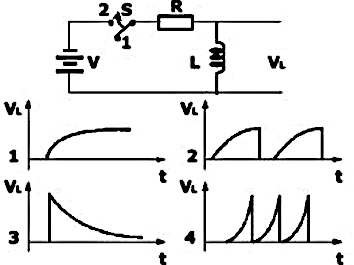
This circuit consists of a voltage source V, a change-over switch S, a resistor R and an inductor L. The voltage/time figures 1 to 4 show possible changes in the voltage V(L) in case the switch S is suddenly shifted from position 1 to 2 at time t = 0. Only one of the diagrams is correct. Which?
Figure 2.
Figure 1.
Figure 3.
Figure 4.
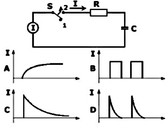
This circuit consists of a current source I, a change-over switch S, a resistor R and a capacitor C. The current/time figures 1 to 4 show possible changes in the current I in case the switch S is suddenly shifted from position 1 to 2 at time t = 0. Only one of the diagrams is correct. Which?
Figure A.
Figure C.
Figure B.
Figure D.
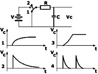
This circuit consists of a voltage source V, a change-over switch S, a resistor R and a capacitor C. The voltage/time figures 1 to 4 show possible changes in the voltage V(C) in case the switch S is suddenly shifted from position 1 to 2 at time t = 0. Only one of the diagrams is correct. Which?
Figure 2.
Figure 3.
Figure 4.
Figure 1.
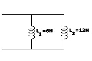
The circuit consists of two inductors, L(1) = 6 H and L(2) = 12 H, connected in parallel. Calculate the equivalent L(S) of the two inductors.
L(S) = 18 H.
L(S) = 6 H.
L(S) = 3 H.
L(S) = 4 H.
Which function is this circuit performing?
Integrating.
Amplifying.
Filtering.
Differentiating.
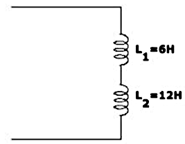
The circuit consists of two inductors, L(1) = 6 H and L(2) = 12 H, in series. Calculate the equivalent L(S) of the inductors.
L(S) = 6 H.
L(S) = 12 H.
L(S) = 9 H.
L(S) = 18 H.
What is an analogous signal?
A digital signal.
A variable electric signal.
A constant signal.
A binary signal.
Where in the personal computer is the BIOS system located?
In the hard drive.
On the motherboard.
In the RAM.
In the CPU cache.
The typical current gain of a common emitter transistor is...
1-10.
10-200.
200-500.
500-1000.
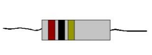
A resistor has three red bands. What is the resistance?
220 ohm.
2 200 ohm.
2 000 ohm.
222 ohm.
The physical size of a resistor is an indicator of its...
Resistance value.
Tolerance.
Power dissipation capability.
Temperature coefficient.
Which electronic component or system of components is this graphical symbol illustrating?
Low-pass filter.
High-pass filter.
Bandpass filter.
Notch filter.
This amplifier circuit is a very common configuration used to amplify the difference in voltage between two input signals; in this case input 1 and 2. What is this amplifier called?
Operational amplifier.
Voltage follower.
Differential amplifier.
Current amplifier.
What is a ZENER BARRIER?
A unit for voltage amplification.
A unit for current regulation.
A zener barrier is a unit made to obtain intrinsically safety in installations for instrumentation in hazardous areas.
A device to convert AC to DC.
These circuits are all active filters. Which of the circuits is a low-pass filter?
Figure 1.
Figure 2.
Figure 3.
Figure 4.
Can a ZENER BARRIER be installed in a hazardous area?
Yes, it can be installed anywhere.
No, as only the output from the barrier is intrinsically safe this is not allowed.
Yes, but only with additional grounding.
Yes, if it is connected to a transformer.
The inductance which will induce an EMF of 1 Volt in a conductor when the current is changing at a rate of 1 Amp per second, is defined as...
Farad.
Ohm.
Henry.
Tesla.
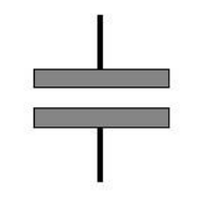
Which electronic component is this graphical symbol illustrating?
Resistor.
Inductor.
Diode.
Capacitor.
Which electronic component is this graphical symbol illustrating?
Resistor.
Variable capacitor.
Potentiometer, 10 kilo-ohms.
Inductor.
Which electronic component is this graphical symbol illustrating?
Diode.
Resistor.
Capacitor.
Transistor.
Which electronic component is this graphical symbol illustrating?
Regular diode.
Light-emitting diode (LED).
Zener diode.
Transistor.
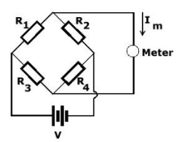
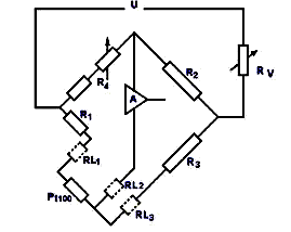
Wheatstone resistance bridge is often used for measuring resistances in, for instance, Pt 100 temperature sensors or strain gauges. This figure is such a bridge. What is the requirement for balance of such a bridge, i. e., the current through the meter i(m) = 0?
R1/R2 = R4/R3.
R1 + R2 = R3 + R4.
R1 * R2 = R3 * R4.
R1/R2 = R3/R4.
Which electronic component is this graphical symbol illustrating?
Capacitor.
Inductor.
Resistance, 3 300 ohms.
Transistor.
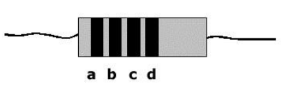
This resistor has the value of 68 k ohm. Which color code will you put on the different color-rings?
a. Red, b. Violet, c. Yellow.
a. Blue, b. Gray, c. Orange.
a. Green, b. Brown, c. Red.
a. Yellow, b. Violet, c. Red.
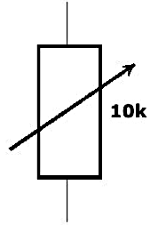
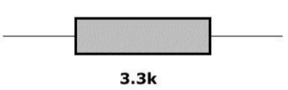
What is the resistance value of this resistor?
1 k ohm.
100 k ohm.
10 k ohm.
22 k ohm.
Which electronic component or system of components is this graphical symbol illustrating?
Transistor.
Differential amplifier.
Operational amplifier.
Resistor network.
A 8-Volt relay is to be used with a 12-Volt power supply. The relay requires a current of 0,1 Amp. What is the series resistance required?
20 ohm.
30 ohm.
50 ohm.
40 ohm.
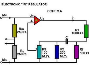
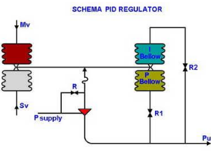
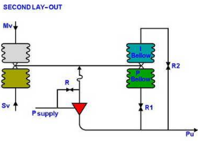
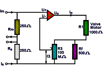
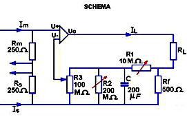
Which resistor determines the proportional band on this electronic proportional integrating controller?
R1.
R2.
R3.
R4.
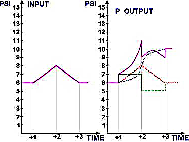
In the output characteristics of this controller, which response lines are clearly shown?
Only proportional.
Only integration and differentiation.
The proportional, integration and differentiation.
None of the above.
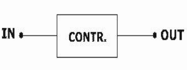
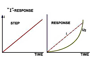
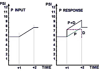
For which kind of controller are the input and output characteristics shown here?
The characteristics shown here indicate a ramp input on the left together with the corresponding output on the right of _____
a proportional controller.
a pure integrator.
a differentiator.
an on-off controller.
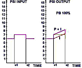
For which control instrument are these the input (left) and the output or response (right) characteristics?
Proportional integrating controller.
Proportional differentiating controller.
Integral controller.
On-off controller.
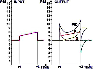
For which type of controller are the input and output characteristics shown here?
Proportional controller.
Proportional integrating controller.
Proportional differentiating controller.
On-off controller.
Fitting a restriction R1 in the supply to the proportional feedback of this PID controller ensures that for an initial small variation on the input, the initial response on the output will be ...
weak.
delayed.
strong.
zero.
What does this symbol represent?
Logic gate (AND).
Binary flip-flop.
Oscillator.
Comparator.
The pick up and the time settings of reverse power relays are adjustable. If the prime mover of the alternator is a steam turbine what is the trip level setting?
5-10 %.
1-2 %.
2-3 %.
10-15 %.
For this PID controller to act only as a P (proportional) controller, what should be the arrangement of restricting valves R1 and R2?
R1 closed, R2 fully open.
R1 fully open, R2 closed.
Both R1 and R2 fully open.
Both R1 and R2 closed.
If the prime mover of an alternator is a diesel engine, what should the Reverse Power Relay`s pick up setting be?
2-3 %.
5-12 %.
12-20 %.
1-2 %.
An ideal operational amplifier is characterised by...
zero input impedance.
infinite input impedance.
low output impedance.
limited gain.
What is a high-pass filter?
A circuit that will only pass low frequency signals.
A circuit that will only pass high frequency signals.
A circuit that blocks both high and low frequencies.
A circuit that amplifies low frequencies only.
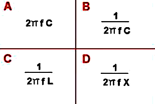
Which of these formulas is used to calculate capacitive reactance (Xc)?
A.
B.
C.
D.
The size of any electrical conductor should be such that in practice, the voltage drop at full load will not exceed _____
5 %.
2 %.
10 %.
1 %.
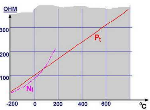
The resistance characteristic of Platinum is linear. The resistance characteristic of Nickel is non-linear. How can the characteristic of Nickel be made linear?
By heating the Nickel.
By fitting another resistance in parallel.
By cooling the Nickel.
By using a series resistor only.
A six pole asynchronous motor is fed from a 60 Hz circuit and has a slip of 5 %. What is the motor speed?
1 200 RPM.
1 000 RPM.
1 080 RPM.
1 140 RPM.
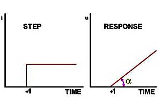
These graphs are, left, the step input and, right, the output response of a controller. What characteristics are shown?
Proportional characteristics.
Differentiator characteristics.
On-off characteristics.
The integrator characteristics.
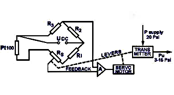
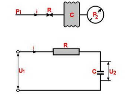
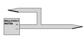
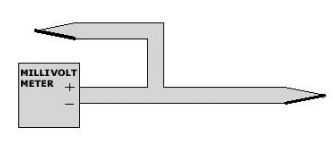
The function of this measuring system is to ...
measure pressure directly.
convert an electric temperature measurement into a pneumatic signal.
convert a pneumatic signal into an electric signal.
display the temperature digitally.
The three conductor system used by Wheatstone Bridge lay-outs is intended to provide...
a more accurate voltage measurement.
compensation for changing conductor resistance by changing temperature.
reduction of power loss.
protection against overload.
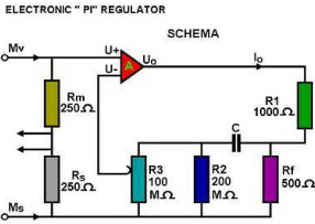
What control equipment drawing is shown here?
An electric PI-controller.
An electric P-controller.
A pneumatic P-controller.
An electric PID-controller.
A six-pole asynchronous motor is connected to a power supply with a frequency of 50 Hz. If the rotor bar frequency is 2,3 Hz, what will be the speed of the motor?
1 000 RPM.
954 RPM.
900 RPM.
975 RPM.
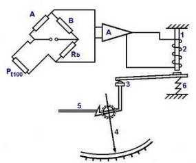
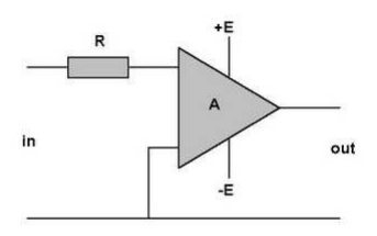
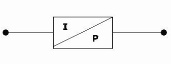
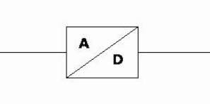
In this drawing, the triangle marked «A» represents _____
a transistor.
an operational amplifier.
a diode.
a resistor network.
How is the differentiating action of this PID controller obtained?
By R2 only.
By C and R1.
By C only.
By R1 and R2.
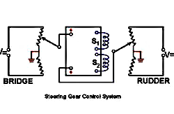
The second potentiometer of this electric command system is located in the steering gear. What moves this potentiometer?
The helm wheel directly.
The rudder position via the trunion connection.
A separate electric motor.
The feedback lever in the bridge.
In these integrator circuits the air flow through the restrictor and the current through the resistance...
increases with time.
decreases with time.
remains constant.
fluctuates randomly.
What is the difference in function between these electrical and the pneumatic integrators?
Electrical integrators are faster.
Pneumatic integrators are more precise.
None.
Electrical integrators cannot handle large currents.
Two 3 phase 4 160 Volt, 60 Hz alternators are operated in parallel. The total load of the system is 1 050 kW with power factor 0,75 lagging. If alternator N°1 is carrying 700 kW at 80 % power factor lagging, _____
the Power Factor of alternator N°2 is leading 0,668.
the Power Factor of alternator N°2 is lagging 0,658.
the Power Factor of alternator N°2 is lagging 0,75.
the Power Factor of alternator N°2 is unity.
From the sample diagrams shown, choose the correct voltage waveform measured across the load.
1.
3.
2.
4.
Alternator (A) 100 kVA runs parallel with alternator (B) 125 kVA, both are 3 phase, 240 V, 60 Hz. The load of A is 60 kW, 90 % power factor and the load of B is 80 kW, 70 % power factor. What is the total load?
400,5 Amp.
429,8 Amp.
450 Amp.
415 Amp.
The power requirements for the excitation winding/circuit for a 3-phase alternator operating at rated output power are supplied by:
An external DC generator.
The alternator's output itself via the automatic voltage regulator.
A battery supply.
A separate AC supply.
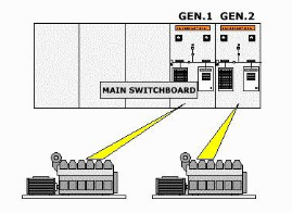
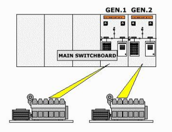
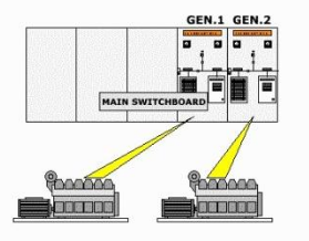
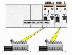
Generator 1 and 2 are working in parallel. Prime-mover 2 suffers a total fuel loss. The likely outcome is:
Both generators continue running.
N°2 generator trips on reverse power.
Generator 1 trips.
No action occurs.
Before taking insulation resistance readings of generator windings the automatic voltage regulators should be isolated and all semiconductor short circuited or disconnected in order to:
Ensure correct voltage readings.
Prevent damage to sensitive electronic components from high voltage tester.
Increase insulation resistance.
Calibrate the generator.
A star connected induction motor operates on 220 V with power factor 0,7 and efficiency of 82 %. Its output is 8 HP. What is the phase current and voltage?
Phase current is 25 A, phase voltage is 127 V.
Phase current is 27,3 Ampere, phase voltage is 127 Volt.
Phase current is 30 A, phase voltage is 110 V.
Phase current is 20 A, phase voltage is 120 V.
How is the set pressure (opening pressure) adjusted on the cylinder head safety valve of a diesel engine?
By changing the valve size.
By adjusting the spring pressure.
By modifying the cylinder head.
By adjusting the fuel injection timing.
Item N° 2 of this Wheatstone Bridge is...
the reference voltage supplied to amplifier A.
the thermal resistance fed by the output of amplifier A.
a fixed calibration resistor used for bridge balancing.
the current-limiting resistor connected to the power supply.
Indicate the correct characteristic of the amplifier «A».
A voltage gain less than 10.
A voltage gain greater than 100,000.
A current gain equal to zero.
A frequency response limited to direct current only.
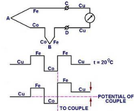
The potential of this thermocouple bridge is zero if all connections are kept at the same temperature. Why is the indication of the potentiometer zero?
Because the thermocouple wires have zero electrical resistance.
Because the connections in A and B and in C and D are opposed.
Because the potentiometer is disconnected from the circuit.
Because the power supply voltage is equal to zero.
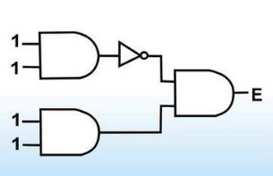
What will be the binary output at E?
1.
0.
High impedance (Z).
Undefined state.
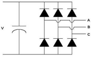
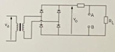
What is the function of the circuit shown here?
Three phase inverter.
Three phase rectifier.
Single phase transformer.
AC voltage regulator.
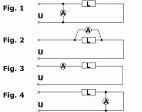
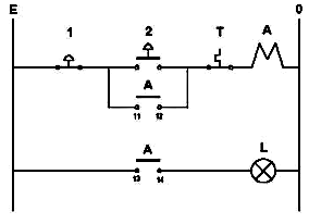
Which alternative is correct for measuring current over the load L?
Figure 1.
Figure 3.
Figure 2.
Figure 4.
A three phase alternator is connected singularly to the main switchboard. The switchboard instruments show 440 Volts/950 amperes. With a power factor of 0,8, what will be the kW load?
724 kW.
579,2 kW.
650 kW.
450 kW.
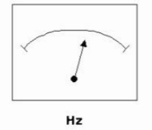
What is Hz the abbreviation for?
Voltage in an Alternating Current (AC).
Frequency in an Alternating Current (AC).
Current in a Direct Current (DC).
Power in an electrical circuit.
Will it matter to the accuracy of the measurement how you are installing a resistance element in a thermo-well?
No, installation position has no effect on accuracy.
Yes, wrong installation will result in a major deviation in measurement.
Only affects response time, not accuracy.
Only affects electrical resistance of the sensor.
After successful synchronising the kW and kVAr loading are respectively transferred by the following controls:
Voltage regulator and speed governor.
Speed governor and voltage regulator.
Excitation system and frequency controller.
Load controller and power factor controller.
It is possible to operate two similar generators in parallel at equal power (kW) but at different power factors. The generator with lower power factor will cause it to run:
Cooler due to reduced current.
Hotter due to increased current.
At the same temperature due to constant kW load.
With reduced mechanical stress only.
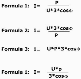
P = U × I × √3 × cos(φ). What is the formula for I?
Formula 1.
Formula 2.
Formula 3.
Formula 4.
What is the purpose of the alternator reverse power trip?
To increase alternator efficiency under load.
To prevent the alternator from «motoring» by being supplied power from other parallel alternator.
To regulate voltage during load changes.
To balance reactive power between generators.
If you alter the field excitation voltage of one alternator operating in parallel, this will cause change in that alternator's:
Active load (kW).
Reactive load (kVAr).
Frequency output.
Mechanical torque only.
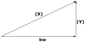
When 3 phase alternators are operating in parallel, it is very important that the reactive load is evenly shared so that the total alternator loads are evenly shared. If the total alternator load is the vector sum of active and reactive loads, which side of the vector diagram shown represents the reactive load?
X.
Y.
kw.
None of the above.
Prior to synchronising, the generator voltage and frequency are respectively controlled by:
Speed governor and AVR.
AVR and speed governor.
Exciter and load controller.
Transformer and regulator.
Regular (at least weekly) testing of the emergency generator must be performed to check:
Its fuel consumption efficiency.
Its readiness to perform as specified.
Its maximum overload capacity.
Its noise and vibration levels only.
Unloading a generator, it is necessary to gradually decrease the load in order to avoid:
Undervoltage.
Undue overspeeding.
Excessive excitation current.
Reverse power flow.
The internal E.M.F. generated in the phase windings of an A.C. generator is controlled by:
Load current and power factor.
The diesel speed and excitation current.
Only the excitation current.
Only the mechanical load torque.
For ideal synchronising, the phase angle difference between the incomer E.M.F. and the busbar voltage should be:
90°.
0°.
180°.
45°.
The correct time to synchronise is usually taken to be when the synchroscope reaches the «5 to 12» position. This is to allow for:
Alternator frequency drift.
Circuit breaker operating time.
Voltage regulation delay.
Load sharing imbalance correction time.
A transformer with 10:1 turns ratio and rated 50 kVA, 2 400/240 Volts, 60 Hz, is used to step down the voltage to a distribution system. The low tension voltage is to be kept constant at 240 Volts. What load impedance connected to the low-tension side will cause the transformer to be fully loaded?
10 Ohms.
15 Ohms.
24 Ohms.
6 Ohms.
A 450 volt 3 phase brushless alternator will have the following combination of items mounted on the rotor:
Permanent magnets/slip rings/AVR.
DC excitation winding/brushes/rotor coils.
3 phase excitation winding/rectifier bank/main field winding.
Stator windings/transformer/diode bridge.
A 450 volt, 859 kW rated generator has not been in operation for several weeks. Prior to starting, insulation resistance readings are taken. The minimum acceptable insulation resistance reading on the main stator winding to allow you to proceed with running the generator is:
1 000 000 Ohms.
100 000 Ohms.
10 000 000 Ohms.
10 000 Ohms.
For two generators running in parallel, their share of additional load (kW) will be determined by the:
AVR settings on each generator.
Governor droop settings on each prime mover.
Excitation current balance.
Load frequency controller.
After main power is restored, a timed sequential restart of motor-driven auxiliaries is necessary to avoid:
Excessive voltage rise on the busbar.
Generator overload due to many motors starting simultaneously.
Reverse power flow into the generator.
Loss of excitation in the alternator field.
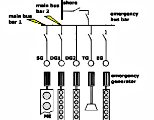
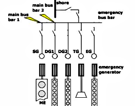
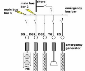
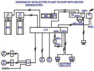
Choose the group of electrical power supplies that best fits the identification of «Mains».
Mains.
N° 1 diesel and N° 2 diesel.
Shore supply and emergency supply.
Battery and UPS supply.
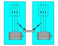
An earth fault exists on the blue line of a 100 A bilge pump circuit. A second earth fault occurs on the yellow line of a 10 A ventilation fan circuit. The likely outcome is that:
Only the bilge pump circuit trips.
A short circuit occurs between earth faults and the ventilation fan fuse blows.
The system continues to operate normally.
Only the insulation monitoring relay alarms without tripping.
A ship's 3-phase a.c. circuit has 440 V and 220 V transformer linked sections. The effect of a single earth fault on a 220 V line will cause the following earth lamp indication:
In 440 V section: One lamp bright, two dim. In 220 V section: One lamp bright, two dim.
In 440 V section: Two lamps bright. In 220 V section: Two lamps bright.
In 440 V section: Two lamps bright. In 220 V section: All lamps off.
In 440 V section: One lamp off, two bright. In 220 V section: One lamp off.
If the A.C. line current in a generator is doubled, the heating effect in the stator windings will:
Double.
Remain the same.
Quadruple.
Be halved.
A motor is protected by a thermal overcurrent relay. After tripping on overload it will not be possible to reset the overcurrent relay because:
The supply voltage is still too high.
The bimetallic strips need time to cool down.
The motor windings are permanently damaged.
The relay requires manual calibration after every trip.
A 3-phase A.C. induction motor is running normally at its rated current of 150 A when a single phasing fault (open circuit) occurs in one line. The likely outcome will be:
Line currents: 150 A, 150 A, 150 A. Trip condition: no trip.
Line currents: 0 A, 180 A, 180 A. Trip condition: trip on overload.
Line currents: 0 A, 75 A, 75 A. Trip condition: trip on undercurrent.
Line currents: 150 A, 0 A, 150 A. Trip condition: trip on reverse power.
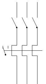
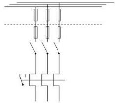
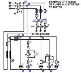
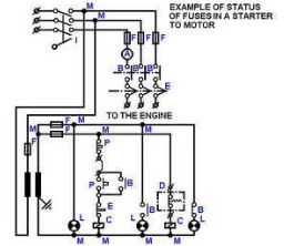
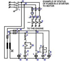
The function of the fuses in a motor starter circuit is to provide:
Overload protection.
Short circuit protection.
Phase sequence protection.
Under-voltage protection.
When a large motor load suddenly is disconnected from the switchboard and the generator is AVR controlled, the voltage will:
Immediately drop and remain below the set value.
Initially rise, then reset to the set value.
Remain constant without any change.
Gradually decrease to zero.
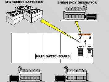
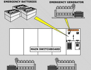
Under normal conditions, the electric power for services supplied from the emergency switchboard is supplied from:
The emergency diesel generator only.
The main diesel generator or shaft generator.
The ship’s battery bank.
A shore power connection.
The insulation resistance (IR) to earth of a new galley hot-plate is measured to be 30 Mohm. When three identical hot-plates are tested together their combined IR will be:
90 Mohm.
10 Mohm.
30 Mohm.
60 Mohm.
The earth lamps in a 3-phase system indicate as follows: Red = bright, Yellow = dark, Blue = dim. The condition indicates:
Hard earth - no fault - light earth.
No fault - hard earth - light earth.
Light earth - hard earth - no fault.
Hard earth - light earth - no fault.
Check-synchroniser equipment is often installed to:
Automatically start the standby generator during a blackout.
Regulate the generator voltage during load changes.
Protect the generator against reverse power.
Due to failure of one of the carbon brushes the excitation voltage is lost on one alternator that is operating in parallel. Will that alternator then:
Take more reactive load while maintaining its share of active load.
Completely loose its share of the load causing the auxiliary engine to speed up.
Trip immediately on reverse power without any change in engine speed.
Increase its terminal voltage and absorb more active power.
A 10 % reduction in generator speed occurs due to a faulty governor. The likely consequence for each motor powered from this generator is to:
Motor will immediately stall due to loss of torque.
Motor speed will increase due to reduced frequency regulation.
Motor speed will remain unchanged because induction motors are independent of supply frequency.
Reduce motor speed by about 10 %.
«Protective discrimination» means the progressive grading of sizes/tripping times of:
Circuit breakers and voltage regulators.
Line fuses and overcurrent relays.
Transformers and alternators.
Motors and synchronising equipment.
A 3-phase induction motor is rated at 200 A. Its initial direct-on-line starting current will be approximately:
600 A.
200 A.
1 000 A.
300 A.
When a blackout occurs: what should be your first reaction?
Immediately restart all machinery without informing anyone.
Wait in engine room until power returns automatically.
Inform the bridge about the reason for blackout, and expected time to restart.
Switch off all breakers and leave the system unattended.
An electrical power emergency source in a ship is required because:
It provides additional propulsion power during heavy weather.
It reduces fuel consumption of the main engine.
It satisfies the SOLAS requirements for ship safety.
It improves the efficiency of cargo handling systems.
Choose the group of electrical power supplies that best fits the identification of «Emergency».
Main switchboard and shaft generator.
Shore supply and main diesel generators.
Emergency diesel and batteries.
Auxiliary generator and alternator AVR system.
What is meant by being intrinsically safe?
The equipment is completely waterproof and dustproof.
The equipment is designed to operate only on low voltage systems.
The equipment cannot produce enough energy to ignite a gas (explode).
The equipment is fully insulated against electric shock.
How do you express the accuracy of an instrument?
In volts per ampere.
In ohms per meter.
In % of full scale.
In watts per second.
Why is it important that a transmitter has been correctly installed at the correct place?
To reduce power consumption of the transmitter.
The control system is depending on the best possible process signal.
To increase the voltage output of the sensor.
To eliminate the need for calibration.
Thermo-elements will typically have:
Very narrow temperature measurement range.
Relatively wide range of temperature measurement.
Fixed single-point temperature measurement only.
No dependence on temperature variation.
Which component does this graphical symbol illustrate?
Local pressure gauge with alarm output.
Remote level controller with indicator.
Temperature transmitter with manual override.
Flow switch with delay timer.
Some equipment may be marked with the following symbol. What does that mean?
Equipment is suitable for high-voltage operation.
Intrinsically safe.
Equipment is waterproof and shockproof.
Equipment is approved for outdoor use only.
Thermistor will typically have:
Completely linear resistance–temperature characteristic.
Relatively non linear characteristic.
No change in resistance with temperature.
Constant output voltage regardless of temperature.
When the cable length from the temperature sensor to the place where we want to read the temperature exceeds approx. 10 meters we normally have to, in case of a Pt 100, in some way compensate for the cable resistance. Do we also have to do this if we choose to use a T802 temperature sensor?
Yes, always, regardless of sensor type.
No.
Only if cable length exceeds 100 meters.
Only if ambient temperature is above 50 °C.
Temperature sensors may be marked Pt 100. What does it mean?
The sensor has a resistance of 100 ohm at 100 °C.
The sensor has a resistance of 100 ohm at 0 °C.
The sensor outputs 100 volts at 0 °C.
The sensor is calibrated for 100 °C maximum temperature.
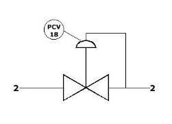
Which component does this graphical symbol illustrate?
Safety relief valve.
Pressure-reducing regulator.
Non-return valve.
Flow control valve.
What is the most common signal from analysis I/P converter?
0–10 V/0–100 psi.
4–20 mA/3–15 psi.
0–20 mA/0–5 psi.
1–5 V/6–18 psi.
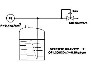
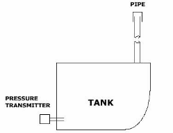
Liquid level in tanks is often measured by measuring the hydrostatic head or differential pressure. One method is the air bubble type which is illustrated here. Calculate the level in the tank, utilizing the figures given on the drawing.
300 cm.
500 cm.
1 000 cm.
250 cm.
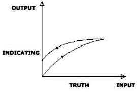
The pressure inlet to a pressure gauge is varied from zero to full scale and back to zero again. The output (indicating pressure) versus true pressure is shown in the diagram. The non-coincidence of loading and unloading curve is due to internal friction in the instrument. What do we call this phenomenon?
Linearity error.
Hysteresis.
Drift.
Repeatability error.
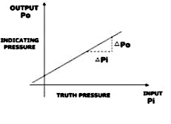
The diagram is a calibration diagram for a pressure gauge. What do you call the slope of the calibration curve?
Hysteresis.
Sensitivity.
Linearity.
Resolution.
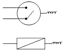
What is the difference between a THERMOSTAT and a TEMPERATURE TRANSMITTER, if any?
A thermostat only measures temperature, while a transmitter only displays it locally.
The thermostat has one or more contacts (open or closed) depending on the temperature/setting. The temperature transmitter converts a temperature signal to an electric signal.
A temperature transmitter is a mechanical device, while a thermostat is electronic only.
There is no difference; both perform identical functions.
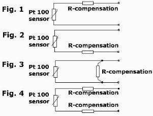
Due to the relatively low resistance of a Pt 100 sensor we might have to compensate for the cable resistance to ensure a correct reading. Which of the 4 alternatives given is correct for the connection of this compensation resistance?
Figure 1.
Figure 2.
Figure 3.
Figure 4.
The range of a transducer is 0–200 bar. The standard output signal is 4–20 mA. What is the output signal when the process value is 100 bar?
10 mA.
12 mA.
16 mA.
8 mA.
When you are calibrating an instrument, what is the most common second step in the procedure (consult the manual)?
Adjust zero offset only.
Check linearity.
Replace the sensor element.
Disconnect the power supply permanently.
In what kind of measuring equipment can we find a Bourdon-tube?
In a temperature transmitter.
In a pressure transmitter.
In a flow meter.
In a level switch.
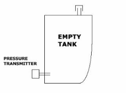
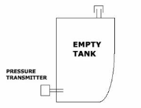
In a fresh water tank we are using a pressure transmitter with a range of 0–0,5 bar/4–20 mA for level measurement. The transmitter is for different reasons installed 30 centimeters from the bottom of the tank, and the tank is 5 meters high. What will the output from the transmitter be when the tank is empty?
20 mA.
12 mA.
4 mA.
0 mA.
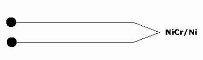
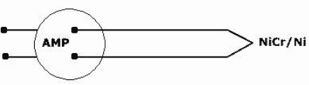
What is the signal we measure from a NiCr/Ni thermocouple?
Ohms (Ω).
Millivolts (mV).
Amperes (A).
Hertz (Hz).
In connection with exhaust gas measurement with a thermocouple we are normally using an amplifier which gives a mA-signal out. Why is this done?
To increase the thermocouple output voltage for local display only.
The signal out from a thermocouple is mV, and cannot be transferred over any longer distance without loss of voltage, giving a very bad accuracy.
To convert temperature directly into a pneumatic signal.
To eliminate the need for calibration of the thermocouple.
Temperature sensors may be marked T802. What does it mean?
802 ohm at 0 °C
802 ohm at 20 °C
802 mV output at 20 °C
802 ohm at 100 °C
What is a typical problem when something is wrong with the span of an instrument?
Hysteresis error.
Zero-point is accurate, but 100 % input is not giving 100 % output.
Linearity error.
Resolution limitation.
What is the advantage of a transmitter with a narrow measurement range?
Faster response time only.
Better linearity and increased accuracy.
Lower power consumption only.
Elimination of calibration requirements.
What is the meaning of instrument calibration?
Adjusting the instrument to increase its range permanently.
Comparing input and output values against a documented standard.
Replacing the sensing element inside the instrument.
Increasing signal strength for remote transmission.
Which of the following detectors will you choose for detecting smoke from fire?
Heat detector.
Ionization type.
Flame detector.
Gas detector.
In installations of INTRINSICALLY SAFE equipment it is required that all equipment should be separated from non-intrinsically safe equipment, and to be of a special colour. What colour is that?
Red.
Yellow.
Blue.
Green.
What is the difference between a PRESSURE SWITCH and a PRESSURE TRANSMITTER, if any?
Both devices only provide a visual indication of pressure without any electrical output.
A pressure switch measures temperature while a pressure transmitter measures flow.
The pressure switch has contact(s) that will change between open and closed position. The pressure transmitter converts a pressure signal into an electric signal.
A pressure switch provides a continuous analog signal, whereas a pressure transmitter only operates in ON/OFF mode.
Which of the following instruments is normally part of a control-loop?
Ammeter.
Thermometer.
Transducer.
Fuse.
When you are calibrating an instrument what is the most common first step in the procedure (consult the manual)?
Disconnect the power supply permanently.
Replace the sensing element.
Record the ambient temperature only.
Adjustment of Zero-point and span.
You have to choose one of the following instruments for measuring pressure in an air bottle in measuring range 0-35 BAR. Which instrument will you install?
Diaphragm level transmitter.
U-tube manometer.
Capsule pressure gauge.
Bourdon Tube manometer.
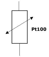
Which type of temperature sensor is used in this temperature measuring system?
Resistance Temperature Detector (RTD).
Thermistor.
Bimetallic temperature sensor.
Thermocouple sensor.
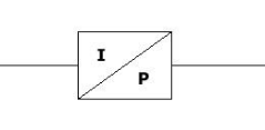
What is an I/P Transducer?
A device that converts pressure into an electrical voltage signal.
A sensor that converts temperature into a pneumatic signal.
A controller that regulates current based on pressure changes.
A transducer that converts a known electric current to a pressure proportional to the current.
Thermocouples are often used for measuring temperatures. Which of the following descriptions are valid for a thermocouple?
A device that measures temperature by changes in electrical resistance.
A junction between two dissimilar metals generates a small voltage.
A sensor that uses infrared radiation to detect temperature.
A mechanical device that expands a bimetal strip when heated.
Which of the listed sensors can not be utilized for detecting temperatures?
Thermocouple.
RTD (Resistance Temperature Detector).
Thermistor.
Strain gauge.
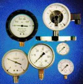
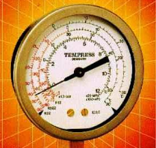
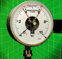
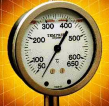
The manometer shown on the picture has an accuracy class 1,0. What is the measuring accuracy if the pointer indicates 6,0 bar?
±0,6 bar.
±0,1 bar.
±0,01 bar.
±0,06 bar.
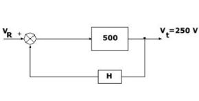
This is a simplified block diagram of a DC generator and its voltage regulator. Find the value of the feedback constant H if the reference VR is a 45-Volt battery and the terminal voltage Vt is to be 250 Volt.
H = -0,15.
H = -0,20.
H = -0,25.
H = -0,178.
Which of the listed physical parameters can be measured by means of a manometer?
Temperature.
Flow rate.
Level.
Pressure.
When calibrating a pressure transducer we have to adjust both SPAN and ZERO. Please indicate in which order these adjustments should be done.
First Span adjustment, then Zero adjustment, then recheck Span.
First Zero adjustment and then Span adjustment. Then Zero should be rechecked.
Zero and Span can be adjusted simultaneously without any sequence.
First adjust Span only, Zero is not required for calibration.
Two reference points for pressure exist, absolute zero and atmospheric pressure. What do you call pressures measured relative to atmospheric pressure?
Absolute pressure.
Differential pressure.
Vacuum pressure.
Gauge pressure.
Two reference points for pressure exist, absolute zero and atmospheric pressure. What do you call pressures measured relative to absolute zero?
Gauge pressure.
Differential pressure.
Vacuum pressure.
Absolute pressure.
U-tube manometers are often used to measure differential pressure. Which of the listed pressures is U-tube manometers mostly used for?
High absolute pressures.
Very high differential pressures.
Medium gauge pressures in industrial systems.
Low differential pressures.
What is an A/D and a D/A converter?
A device that amplifies analogue signals without converting them.
A device that converts only digital signals into mechanical movement.
A converter that converts an analogue signal to a digital signal and vice versa.
A sensor that measures pressure and displays it directly without conversion.
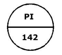
Which component does this graphical symbol illustrate?
Temperature controller installed on panel/console.
Flow transmitter installed in pipeline.
Level switch mounted in tank.
Pressure indicator, installed on panel/console.
Which component does this graphical symbol illustrate?
Pressure indicator.
Flow transmitter.
Temperature sensor.
Pressure to electric current converter.
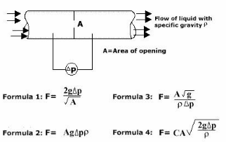
Liquid flow through pipe lines is often measured by means of differential pressure across a restriction (orifice) in the pipe as illustrated by this figure. Which of the listed formulas will you utilize for calculating the volumetric flow F?
Formula 1.
Formula 2.
Formula 3.
Formula 4.
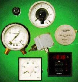
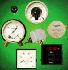
Which type instrument is shown on this picture?
Bourdon tube pressure gauge.
Differential pressure transmitter.
Digital pressure indicator.
Electric Contact manometer.
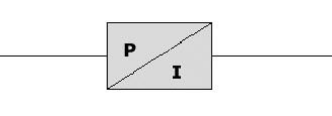
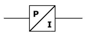
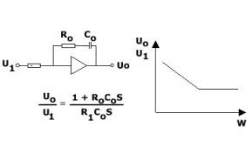
This circuit symbol is an amplifier system and its frequency response diagram. Which control function is the system performing?
Proportional (P).
Proportional + Derivative (PD).
Integral (I) only.
Proportional + integral (PI).
When we are measuring flow of fluids with a fixed area flow meter, the name of the sensing device is:
Venturi tube.
Pitot tube.
Rotameter.
Orifice plate.
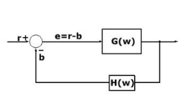
This block diagram illustrates an elementary control system. What do we call such system in general?
Open loop control system.
Manual control system.
Feedforward control system.
Closed loop feed back system.
The range of a transducer is 0–200 bar. The output signal is 4–20 mA. What is the span of the output signal?
4 mA.
16 mA.
12 mA.
20 mA.
Which of the following detectors will you choose for detecting torque of a steel shaft?
Thermocouple.
Pressure transducer.
Displacement sensor.
Strain gauge.
Which of the following detectors will you use for detecting if a watertight steel door is closed or open?
Pressure switch.
Temperature sensor.
Flow meter.
Proximity switch.
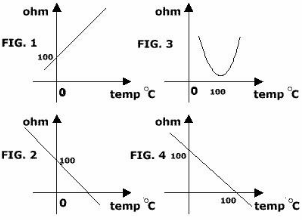
Temperatures are often measured by means of platinum resistance sensors. These curves are all calibration curves. Which of the curves is calibration curve for a Pt 100 sensor?
Figure 2.
Figure 3.
Figure 4.
Figure 1.
The picture shows a liquid filled thermometer. Liquid filled thermometers and manometers are often installed onboard ships. What is the main purpose by the liquid filling of such pointer instruments?
To increase measurement range of the instrument.
To improve electrical conductivity inside the sensor.
To reduce response time of temperature changes.
Reduce mechanical wear on the internal parts caused by vibration.
These circuit diagrams illustrate four different methods of wiring between a Pt 100 temperature sensor and its signal processing electronics. Which of the wiring methods gives the best measuring accuracy?
Figure 2.
Figure 3.
Figure 4.
Figure 1.
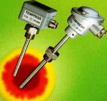
Which type temperature sensors are shown on this picture?
Thermocouple sensors.
Infrared sensors.
Bimetallic sensors.
Resistance sensors.
Which of the following temperature sensors does normally give the highest measuring accuracy?
Thermocouple sensor.
Thermistor sensor.
Bimetallic sensor.
Resistance sensor, Pt 100.
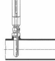
Temperature sensors of all types are normally mounted in a well, or pocket, when used in pipelines. Why?
To increase the electrical signal strength of the sensor.
To reduce heat loss from the pipeline to the surroundings.
To improve pressure measurement accuracy.
Allow removal of the sensor also when liquid is flowing in the pipe.
In a fresh water tank we are using a pressure transmitter with a range of 0–0,5 bar/4–20 mA for level measurement. The transmitter is installed 30 cm from the bottom of the tank, and the tank is 5 meters high. What will the output from the transmitter be when the tank is full (no calibration is made)?
20,0 mA.
16,0 mA.
12,0 mA.
18,8 mA.
In a fresh water tank with a height of 5 meters we shall use a pressure transmitter for level measurement. The tank has a vent-pipe leading to deck 8 meters above the top of the tank. What pressure shall we use as a guidance when ordering the pressure transducer?
0,5 bar.
0,8 bar.
2,0 bar.
1,3 bar.
What is the definition of DEAD BAND?
The time delay between input and output response of a system.
The range of input in which no output change occurs.
The maximum output of a control system.
The change needed in the input signal to produce a change in the output signal.
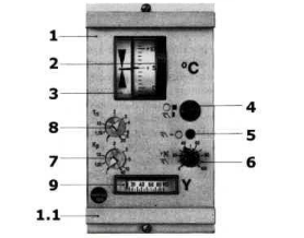
This is an electronic temperature controller. You have been asked to adjust the controllers integrating action. Which button on the front of the controller shall be utilized for this adjustment?
Pos. 6.
Pos. 8.
Pos. 2.
Pos. 9.
When we are measuring viscosity with a restricted flow viscometer, the name of the sensing device is:
Rotational spindle.
Capillary tube.
Ultrasonic probe.
Pressure diaphragm.
Which of the following letter combinations represents a flow indicating controller on a process and instrumentation diagram?
FIS.
FIC.
FCV.
FIT.
Which of the following letter combinations represents a temperature controller on a process and instrumentation diagram?
TI.
TC.
TT.
TV.
What is the purpose of the Oil Mist Detector?
To measure the lubrication oil pressure in the engine.
To monitor the temperature of the crankcase.
To detect oil mist (explosive atmosphere in the crankcase).
To control the fuel injection timing.
Which component does this graphical symbol illustrate?
Thermocouple.
Resistance temperature sensor.
Pressure transmitter.
Flow switch.
When we are measuring level of liquids with a differential pressure meter, the name of the sensing device is:
Capillary tube.
Float switch.
Pressure diaphragm.
Ultrasonic transducer.
When we are measuring temperature with a thermistor, the name of the sensing device is:
Bimetallic strip.
Thermocouple junction.
Temp sensitive semi-conductor.
Gas-filled bulb.
When we are measuring salinity with a salinometer, the sensing device is:
Capillary tube.
Electrodes.
Bimetallic strip.
Optical prism.
One or a certain number of smoke sensors are switched off during routine maintenance work to prevent false alarm. During coffee break the following precautions are taken:
The fire detection system remains disabled until maintenance is completed.
Only the audible alarms are reengaged while the sensors remain switched off.
All alarms are reengaged prior to switching to UMS-mode.
The ventilation system is stopped instead of reactivating the alarms.
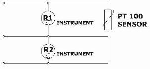
In the diagram below we want to verify the resistance of the PT100 sensor. What is the correct calculation?
R(Pt100) = R1 + R2.
R(Pt100) = R1 × R2.
R(Pt100) = R1 - R2.
R(Pt100) = R2 - R1.
Which of the following letter combinations represents a level indicating controller on a process and instrumentation diagram?
LIT.
LIC.
LCV.
LS.
When we are measuring level of liquids with a conductivity level indicator, the name of the sensing device is:
Float mechanism.
Ultrasonic transducer.
Electrodes.
Pressure diaphragm.
Which of the following measurements will include a D/P transmitter in the control-loop?
Flow.
Level.
Pressure.
Temperature.
The pair of instruments necessary for generator synchronising are:
Ammeter and frequency meter.
Voltmeter and synchroscope.
Wattmeter and ohmmeter.
Phase meter and tachometer.
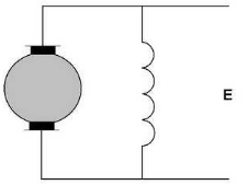
In a «shunt» DC motor how are the pole windings connected?
In series with the armature.
In parallel with the armature.
Not electrically connected to the armature.
Connected only during starting.
Before starting any maintenance on an electrical motor what should you do?
Only isolate the control circuit.
Check the motor temperature only.
Run the motor at low speed for testing.
All of these.
What determines the power factor of an alternator when it is connected singularly to the switchboard?
The excitation current of the alternator only.
The speed of the prime mover.
The load connected to the switchboard.
The ambient temperature of the generator room.
With two alternators running in parallel, you wish to stop one. The first step is to:
Trip the circuit breaker immediately.
Increase the load on the alternator to be stopped.
Remove the load from the alternator to be stopped.
Switch off the excitation system first.
With N°1 and N°2 alternators running in parallel and the kW loads equally shared, one alternator is drawing much higher current than the other. What does this indicate?
The frequency settings are incorrect and both governors must be adjusted.
One alternator is overloaded and must be immediately disconnected.
The alternators are not generating the same voltages and should be adjusted on automatic voltage regulator rheostats.
The excitation system of both alternators is faulty and must be replaced.
At which point do you engage the main circuit breaker of the incoming alternator when paralleling two alternators?
When the voltage difference between the alternators is at maximum.
When the synchronoscope pointer is rotating rapidly clockwise.
When the pointer of the synchronoscope is at 0.
When the incoming alternator frequency is much lower than the busbar frequency.
With two alternators operating in parallel at 75 % load capacity, one trips without any warning. What is the first action that should be taken?
Immediately restart the tripped alternator.
Increase excitation on the remaining alternator.
Trip/stop all nonessential loads that are connected to the switchboard.
Open the bus tie breaker immediately.
You have just synchronized a second alternator onto the main switchboard, and want to equally share the load between the «on» and incoming alternators. What would you do first?
Increase excitation on the incoming alternator and reduce excitation on the running alternator.
Trip the incoming alternator breaker and resynchronize.
Raise the governor speed controller of the incoming alternator and reduce the governor speed controller of the alternator already on the switchboard.
Increase the busbar voltage to force equal load sharing.
When paralleling two alternators they must have:
Same frequency.
Same voltage.
Same phase sequence.
All of the mentioned alternatives.
You are paralleling two alternators and the pointer of the synchronoscope slowly stops rotating and remains stopped in one position before the circuit breaker is closed. This would indicate:
The voltage of the incoming alternator is too high.
The phase sequence is incorrect.
The frequency of the incoming alternator is the same as that of the main switchboard.
The alternator is not excited.
Why should a stationary alternator not be connected to live bus bars?
Because the alternator will immediately reach overspeed.
Because the bus bars will be short circuited.
Because the alternator frequency will automatically synchronize.
Because the excitation system will be permanently damaged.
How would you initiate a test, if found necessary, to find out if an alternator preference system is working?
By increasing the excitation voltage of the generator.
By lowering the generator frequency.
By disconnecting the voltage regulator.
By increasing the generator terminal voltage.
What happens to the terminal voltage of a generator when it supplies a leading power factor load?
It falls significantly.
It remains constant.
It rises.
It becomes zero.
How many sliprings with carbon brushes are fitted on the rotor of a separately excited three-phase alternator?
One.
Two.
Three.
Four.
At what percentage of the motor name plate rating can a thermal overload relay be safely set for continuously rated motors with service factor 1,15?
100 %.
105 %.
115 %.
125 %.
Which are the two requirements to make electricity generation possible?
Presence of high temperature and insulation.
Presence of magnetic flux, relative motion between conductor and flux.
Presence of resistance and capacitance.
Presence of alternating voltage and current.
What is the advantage of a fuse over a circuit breaker with regard to short circuit protection?
It can be reset immediately after operation without replacement.
It provides adjustable tripping characteristics.
Its very high speed breaking operation.
It allows remote control and monitoring.
What happens to the characteristics of a 3 phase induction motor if the applied voltage is slightly reduced?
Current increases, torque increases, and speed decreases significantly.
Current and torque decrease, speed remains constant.
Current decreases, torque increases, and speed increases.
Current remains constant, torque increases, and speed decreases.
For instantaneous operation of preference overload tripping, at what percentage of the total rated current is the device usually set?
90 %.
100 %.
110 %.
125 %.
If open circuit and interruption of current continuity occur in the windings of an electric motor it is called _____
Earth fault.
Short circuit fault.
Winding break.
Overload condition.
What are the functions of the Under Voltage Release Unit on the generator circuit breaker?
It only provides short-circuit protection for the generator.
It prevents overcurrent conditions in the stator windings.
It allows manual synchronizing of alternators.
All of these.
If a total short circuit occurs on a 3 phase alternator and the short-circuit trip fails to operate, what back-up safety device will activate?
The overcurrent relay.
The reverse power relay.
The earth fault relay.
The under voltage trip.
A generator's Reverse Power protection relay is fitted between _____
the exciter and the rotor.
the governor and the fuel system.
the generator and the bus bars.
the transformer and the load.
How many seconds time delay is considered normal before a generator's Reverse Trip Relay operates?
0,5-1 second.
1-2 seconds.
3-5 seconds.
10-15 seconds.
The phase-to-phase voltage of a star connected alternator is 254,34 Volt. What is the equivalent line-to-line voltage?
415 Volt.
380 Volt.
440 Volt.
220 Volt.
If the governor of the driving machine of an alternator malfunctions, which safety device will trip the main breaker?
The reverse power relay.
The overcurrent relay.
The high/low frequency trip.
The earth fault relay.
For an overload of 25 % of the full rated current how long compared to tripping a circuit breaker would a fuse take to blow?
Much faster.
Slightly faster.
Longer.
Instantaneous.
When parallel running alternators, what affects the reactive power of each alternator (kVAR)?
The engine governor setting.
The load current only.
The excitation current.
The frequency of the system.
The ship's insulation meter indicates a low resistance in the electrical distribution system, which of these is the most likely cause?
A dry cable joint in a terminal box.
An open circuit in one phase conductor.
A connection box has been filled with salt water.
A correctly installed insulated cable system.
The Main as well as the Emergency switchboard are panels where the electric power is _____
locally.
individually.
centrally.
fed into, monitored and supplied to the consumers.
In which part of a large alternator is the electric power produced?
In the rotor.
In the exciter.
In the stator.
In the governor system.
How is the voltage output of an alternator controlled?
By the alternator speed.
By the excitation current.
By the load current.
By the power factor of the load.
Typically, how many times full load current are motor fuses rated in order to withstand the large starting current?
1-1,5 times.
2-3 times.
5-6 times.
10-12 times.
What happens to the terminal voltage of an alternator producing 440 Volt when it supplies a lagging power factor load, example induction motors?
The terminal voltage will rise above 440 Volt.
The terminal voltage will remain exactly 440 Volt.
The terminal voltage will drop below 440 Volt.
The terminal voltage will become unstable and oscillate to zero.
What is the meaning of item «CP» in this ship's electric plant diagram?
Control panel.
Circuit protector.
Charging panel.
Main switchboard.
The principle of an automatic voltage regulator (AVR) is to produce an excitation current proportional to what?
Only the output current of the alternator.
Only the output voltage of the alternator.
The speed of the prime mover.
The output voltage and the output current of the alternator.
How can the direction of a three phase induction motor be reversed?
By increasing the supply voltage.
By changing the frequency of the supply.
By changing the position of the entry cable on two terminals.
By reducing the load on the motor.
Which of the following safety devices fitted on the main breaker will trip the alternator if a major cabled line to the distributors should fail and the insulation break through?
The reverse power protection.
The under voltage protection.
The earth fault protection.
The short circuit protection.
If the governor of the driving machine of an alternator malfunctions, which safety device will trip the main switch breaker?
The reverse power relay.
The overcurrent protection.
The earth fault protection.
The high/low frequency trip.
A breakdown in insulation between a motor winding and the motor frame is called _____
a short circuit.
an open circuit.
an overload.
an earth.
How is the excitation current transmitted to the rotor?
Via a rectifier and inverter system.
Via transformer windings only.
Via slip rings and brushes.
Via the stator windings.
The breakdown in insulation between one or more windings or one or more coils inside an electric motor is called _____
an earth fault.
a short circuit fault.
an overload condition.
an insulation breakdown.
When a DC generator is short circuited, how is the output voltage affected?
It increases sharply.
It remains constant.
It becomes unstable and fluctuates.
It falls to zero.
When two generators are being manually synchronized, when should the circuit breaker be closed?
When the synchroscope is stationary at 12 o’clock position.
When the synchroscope is rotating quickly clockwise at any position.
When the synchroscope is rotating slowly clockwise and at the 11 o’clock position.
When the synchroscope is rotating rapidly counterclockwise.
In a Star-connected 3-phase motor...
The line current is equal to the phase current.
The line current is √3 times the phase current.
The phase current is always zero.
The line current is half of the phase current.
What will be the most likely equipment to be disconnected by the preferential trip?
Steering gear.
Emergency lighting.
Galley.
Fire detection system.
The kWatt indicator shows 300 kW and the kVAR indicator shows 200 kVAR. What is the Power Factor?
0,60
0,75
0,832
0,95
In an alternator what effect does increasing the excitation have?
It increases the speed of the alternator.
It decreases the frequency of output.
It increases the voltage produced in the conductor.
It reduces the load current automatically.
The torque developed by a three phase induction motor is dependent on which of the following?
Its speed only.
Its voltage, current and impedance.
Its frequency only.
Its power factor only.
When two diesel generator sets are running in parallel during your engine room watch, what should you periodically check?
That both diesels have the same load in kW only.
That both diesels have the same frequency only.
That both diesels have the same load in kWat, same reactive load in kVAR, and same amperage.
That both diesels have identical fuel consumption rates.
What is the result if a motor runs at a frequency higher than its designed operating frequency?
It will run slower and reduce torque.
It will stop immediately due to protection.
It will run faster and be overloaded.
It will maintain constant speed regardless of frequency.
What will happen when push-button 2 is pressed?
The relay coil A will activate only while button 2 is pressed.
The relay coil A will not activate at all.
The relay coil A will activate and remain activated even after button 2 has been released.
The relay coil A will activate and immediately de-energize due to overload.
If the insulation fails on a major distribution cable, which alternator breaker trip will operate?
The reverse power protection.
The under voltage protection.
The earth fault protection.
The short circuit protection.
Why are interpoles fitted to DC generators?
To increase the generated voltage.
To reduce mechanical vibration.
To counter field distortion.
To increase the speed of the generator.
Complete the sentence. A series-wound generator has the field windings in series with its _____.
shunt.
parallel.
auxiliary.
armature.
What can cause etched or burned bands on the contact faces of brushes in a DC motor?
Excessive lubrication of the commutator.
Low supply voltage.
Brushes improperly positioned.
Oversized motor windings.
An unidentified feeder supplies three motors with full load currents of 15, 40 and 52 Amps each. What is the minimum size of the motor feeder in «ampacity»?
100 Amps.
120 Amps.
140 Amps.
160 Amps.
The phase current in a Delta connected alternator is found to be 127 A. What is the line current?
127 A.
180 A.
219,97 A.
240 A.
In the event of total immersion of an electric motor in sea water what corrective action should you take to make the motor operational again?
Dry it by running the motor under load immediately.
Rinse with fresh water only and put it into service.
Wash with tetrachloride, heat to 80 °C.
Apply oil to the windings and energize slowly.
What are the items «PP» indicated in this electric starting diagram?
Pressure switches.
Pilot lamps.
Power panels.
Stop push buttons.
What should be the minimum current carrying capacity of branch circuit conductors supplying a single motor?
100 % of the full load current name plate rating.
110 % of the full load current name plate rating.
125 % of the full load current name plate rating.
150 % of the full load current name plate rating.
What does item «CE» stand for in this ship's electric plant drawing?
Control Equipment.
Charging Engine.
Central Earth.
Emergency Switchboard.
How many watts are there in one horsepower?
736 Watts.
746 Watts.
1 000 Watts.
550 Watts.
A split-phase motor is an induction motor where the magnetic fields are produced by _____ that causes the motor to rotate.
a single stator winding only.
DC excitation of the rotor.
the main and the auxiliary windings.
permanent magnets in the rotor.
Three motors with full load currents of 15, 40 and 52 Amps each are fed by an unidentified feeder. What is the minimum size of the motor feeder current carrying capacity?
107 A.
120 A.
134 A.
160 A.
A 20 Amp motor operates from a 240 V insulated system. The cable impedance is 0,01 Ohm. What current will flow in case of an earth fault?
2 400 A.
20 A.
240 A.
0 A.
How is the direction of rotation changed in an asynchronous motor?
By increasing the supply voltage.
By changing the supply frequency.
By switching two of the three connections on the motor terminal.
By reducing the load on the motor.
What possibilities exist to supply power via direct connection to the Emergency Switchboard?
Supply by shore connection only.
Supply by main switchboard and supply by emergency diesel.
Supply only by batteries.
Supply only by main generator.
How can you monitor the correct instant for synchronising alternators should your synchronising system (synchronoscope or lamps) be defective?
By using a frequency meter only.
By fitting a voltmeter over one phase.
By measuring only the current of the incoming generator.
By increasing excitation of both generators.
A current clamp meter is clipped around a cable supplying a balanced three phase motor working at full load. The motor is rated to consume 100 A. What will the meter show?
100 A.
173 A.
0 A.
300 A.
What does item «C» indicate in this electrical starting circuit?
Start push button.
Overload relay.
Auxiliary contact.
The main contactor.
What does item «RT» represent in this schematic electrical starting diagram?
The timer relay.
The overload relay.
The main contactor.
The start push button.
What are the electric power suppliers on board this ship?
2 Main Diesels, 2 Emergency Diesels, 1 Shore Connection.
2 Main Diesels, 1 Emergency Diesel, 1 Turboalternator.
1 Main Diesel, 1 Emergency Diesel, 2 Battery Banks.
3 Main Diesels and 1 Shaft Generator.
If a fault has occurred (shorted, earthed) in an electric motor, you should ____.
replace only the blown fuse
replace all three fuses, blown or not.
reset the motor and continue operation
interchange the remaining fuses
What information would you find on the name plate of any industrial transformer?
Power factor, frequency, lubrication type, and cooling water pressure.
kVAR rating, voltage, impedance, BIL rating, polarity.
Shaft speed, torque, bearing type, and insulation resistance.
Fuel consumption, exhaust temperature, and engine efficiency.
When will the left hand lamp «L» illuminate? (Assume there is no defect in the installation)
When the start push button is pressed.
When the main breaker is switched on.
When the overload relay trips.
When the emergency stop button is activated.
Arc chutes in circuit breakers are efficient devices for quenching arcs in air because they _____.
increase the contact resistance and reduce the current
confine the arc, control its movement and provide rapid cooling.
store electrical energy for later discharge
convert electrical energy into mechanical motion
DC generators are rated in...
kVA.
kW.
Hertz.
Amperes.
The voltage in a 60Hz AC generator is adjusted by _____.
changing the load current.
the magnetic field strength.
changing the frequency.
altering the rotor speed only.
In DC generators what effect can be caused by armature reaction?
Increased output voltage stability
Arcing at the brushes.
Reduced mechanical vibration
Improved commutation
What are items F indicating in this starting box drawing?
The contactors.
The fuses.
The overload relay.
The control transformer.
What is the function of the voltage regulator fitted to AC generators operating in parallel?
To control the frequency of the system.
To divide the reactive current equally between the generators.
To increase the mechanical output of the prime mover.
To synchronize the phase sequence of the generators.
What could item D represent in this electric starting diagram?
The main contactor.
Any of these.
The overload relay.
The control fuse.
The failure of an AC generator to pick up voltage may be caused by:
Overspeed of the prime mover.
Failure of the exciter.
Excessive load on the generator.
Incorrect frequency setting.
When an electric motor is operated at a higher frequency, it will run _____ and it may be operating _____.
slower and underloaded
faster in overload.
at constant speed with reduced current
slower in overload conditions
What are items «E» in this starting circuit diagram?
The main contactor.
An overload relay/stop button.
The control transformer.
The fuse holders.
What is the purpose of the preference load tripping system?
To increase generator voltage during peak load conditions.
To disconnect non-essential equipment in case of generator overload.
To synchronize generators automatically.
To balance reactive power between generators.
How will you find out if an electric motor has developed an earth fault?
By measuring the running current under load.
By carrying out a Megger test.
By checking the shaft speed with a tachometer.
By measuring the supply frequency.
How is the power output of an alternator controlled?
By changing the mechanical speed of the prime mover.
By the excitation current in the rotor.
By changing the load frequency directly.
By reducing the stator resistance.
With large load change what maintains steady voltage?
Automatic voltage regulator (AVR).
Flywheel & governor.
Circuit breaker and fuse system.
Synchronizing panel.
What do items «C» represent in this starter diagram?
Contactors.
Relays.
Fuses.
Push buttons.
How is the direction of a three-phase induction motor reversed?
By increasing the supply voltage.
Change the position of the entry cable on two terminals.
By reducing the load torque.
By changing the rotor resistance only.
What is required to generate 50 Hz using a slow speed prime mover?
Increased rotor speed.
Increased number of poles.
Reduced excitation current.
Decreased load resistance.
An earth fault on an electrical motor can be defined as an electrical connection between its wiring and its...
rotor windings.
supply terminals.
metal frame work.
control circuit.
What units are used to measure back EMF?
Amperes.
Ohms.
Volts.
Watts.
What is the first step when removing a generator from parallel operation with other generators?
Trip the circuit breaker immediately.
Reduce excitation to zero.
Remove the load from the generator to be stopped.
Increase engine speed before disconnecting.
Which is true in a Star-connected 3-phase motor?
The line voltage is equal to the phase voltage.
The line current is equal to the phase current.
The phase voltage is higher than line voltage.
The power factor is always unity.
AC generators are rated in...
kW.
kVA.
Hertz.
Ohms.
What units measure counter electromotive force or back EMF?
Amperes.
Watts.
Volts.
Hertz.
Which is the best way to give an electric motor a complete winding and insulation test?
Using only a multimeter resistance test.
All of these.
Running the motor under load only.
Checking only phase continuity.
What is the purpose of the reverse power relay connected to an AC diesel generator?
To increase generator output during overload conditions.
To prevent the generator being run as a motor.
To regulate the frequency of the system.
To balance reactive power between generators.
The best way of testing the «stand-by» function of the emergency diesel alternator is by _____
manually starting the engine locally.
simulating a load increase on the generator.
by switching off the emergency switch board supply breaker on the main switch board.
disconnecting the battery charger only.
What type of instrument can be used to locate an earthed field coil in a synchronous motor?
A megger (insulation tester).
An ohmmeter.
A wattmeter.
A clamp ammeter.
What will happen when an earth fault occurs on one line of an insulated distribution system?
The system will immediately shut down automatically.
No fuses will trip, the system is isolated from the earth.
All loads will lose power instantly.
The generator will reverse rotation.
If an alternator runs at 900 RPM and delivers AC current at 60 Hz, how many pole pairs has this alternator got?
Two.
Four.
Six.
Eight.
What type of equipment is represented by this symbol?
A series motor.
A shunt motor.
A synchronous generator.
A transformer.
In extreme circumstances what is the allowable max & min voltage tolerance?
90 % - 110 %.
85 % - 120 %.
95 % - 105 %.
80 % - 100 %.
In the event of total immersion of an electric motor in sea water or oils, what corrective action should you take to make the motor operational again?
Dry the motor by running it under load immediately.
Wash with fresh water, wipe dry and re-varnish windings.
Apply compressed air only and return to service.
Replace only the bearings and reuse the windings.
What are the items «CD» shown in this ship`s electric plant diagram?
Control relays.
Distribution panels.
Circuit breakers.
Synchronizing lamps.
Which of the following groups of motors are all DC motors?
Squirrel cage, slip ring and synchronous.
Shunt, series and compound.
Induction, synchronous and reluctance.
Single phase, three phase and universal.
What are items «T» shown in this ships electric plant schematic diagram?
Transformers.
Circuit breakers.
Alternators.
Busbars.
In a DC generator, where is the current generated?
In the field windings.
In the armature windings.
In the commutator segments.
In the brushes.
What determines the output voltage of an AC alternator?
The speed of the prime mover.
Strength of magnetic field.
The resistance of the stator windings.
The number of connected loads.
When taking over the engine room watch, what should you check in the first place concerning the auxiliary diesels and electric power supply?
The color of the exhaust gases and the temperature of the engine room.
That the load, Hertz and Voltage are normal, any other power requirements are in Chief Engineer`s standing orders, number of generators on load.
The quantity of fuel in the storage tanks only.
The cleanliness of the switchboard and lighting conditions.
It is said sometimes that alternators are operating as a load, i. e. as a motor. What are the circumstances for this to occur?
When the excitation current of the alternator is increased above its rated value.
When the alternator is operating at a higher frequency than the main switchboard.
When the alternator in question has lost prime mover input.
When the alternator is supplying power to an inductive load.
When taking over the engine room watch, what should you verify on the electrical main switch board?
The color coding of the cables and the cleanliness of the switchboard.
The ambient temperature and ventilation of the engine control room only.
Power Generation, power distribution inclusive secondary circuit, any unusual power consumer switched on/off, earth faults main and secondary systems.
The paint condition and mechanical fastening of the switchboard panels.
In a series wound generator what is the connection between field and armature currents?
They are connected in parallel and operate independently.
The field current is supplied from an external excitation source.
Series connected.
The field current flows only during starting and is then disconnected.
What is the purpose of the parts circled in red?
To increase the motor starting torque.
To provide electrical insulation between windings.
To assist the motor cooling.
To reduce mechanical vibrations of the motor.
If a cable length 100 m, dia. 1,25 mm has a resistance of 30 Ohm, what length cable of the same material with dia. 0,75 mm has a resistance of 25 Ohm?
15 metres.
30 metres.
50 metres.
75 metres.
What is the function of component number 6?
To provide electrical insulation between the rotor and the stator.
To locate the bearing.
To increase the rotational speed of the shaft.
To supply lubrication to the winding system.
The commutator of a DC generator is examined and is found to have a smooth appearance and a dark chocolate colour. What action would you take?
Clean the commutator with emery cloth to make it shiny.
Increase the brush spring pressure to improve contact.
None, this is how it should appear.
Replace the commutator due to overheating.
Why is synchronization required when one alternator is to be paralleled with another?
To ensure the output voltage is reduced before connection.
To match the insulation resistance of both machines.
If two unsynchronized generators are connected, both the diesel prime mover and the generator can be damaged.
To allow the frequency to automatically correct itself after connection.
Can the speed of an asynchronous motor be regulated?
No, it is fixed and cannot be changed under any conditions.
Yes, if a thyristor regulator is used.
Only by changing the rotor resistance permanently.
Only by mechanically changing the number of poles during operation.
What would be the correct setting of the current relay for a three phase induction motor?
At 50–75 % of the rated current.
At exactly the rated current (100 %) to ensure immediate tripping.
At 5–15 % over the rated current.
At twice the rated current for short circuit protection.
The principle of an automatic voltage regulator (AVR) is to produce an excitation current proportional to _____
the inverse of.
only the output voltage, ignoring current variations.
the phase angle between.
the output voltage and the output current of the alternator.
What is the purpose of the component number 5?
To increase the starting torque of the motor.
To provide electrical protection against overload conditions.
Motor cooling.
To reduce noise and mechanical vibration during operation.
What is the purpose of the part circled in red?
To provide mechanical support for the rotor shaft.
To house the terminals.
To act as the cooling fan cover for the motor.
To increase magnetic flux in the stator core.
What could cause sparking and grooving of the commutator in a DC motor?
Excessive brush pressure or worn brushes.
Incorrect brush position or poor commutation.
Overload conditions causing heavy current.
Any of the other options.
In a «shunt» DC motor how are the pole windings connected?
In series with the armature winding.
In parallel with the armature.
Connected only during motor starting.
Connected to an external excitation transformer.
Before starting any maintenance on an electrical motor what should you do?
Only check the mechanical condition of the motor casing.
Ensure the motor is running at no load.
Disconnect and lock out the electrical supply and verify isolation.
All of these.
Which is the best way to give an electric motor a complete winding and insulation test?
Using a megohmmeter (insulation resistance test).
Performing a continuity test on all windings.
Conducting a high-potential (hipot) test where applicable.
All of these.
What prevents a stationary alternator from being connected to live bus-bars?
Reverse power relay.
Overcurrent protection relay.
No volt trip.
Underfrequency relay.
What would be the correct setting of the current relay for a three phase induction motor?
At 20–30 % below the rated current.
At exactly the rated current (100 %) for instant protection.
At 5–15 % over the rated current.
At double the rated current for short-circuit protection.
What is component number 2?
The rotor shaft.
The stator winding.
The cooling fan assembly.
The terminal box cover.
What method should be used for achieving «reduced voltage starting» for large AC motors?
Direct-on-line (DOL) starting.
Star-delta starting or autotransformer starting.
Rotor short-circuiting during start.
Any of these options.
For what type of load would a star/delta starter be employed?
High starting torque loads such as cranes and winches.
Very light no-load motors only.
An air start compressor.
DC motor applications requiring field control.
In a series wound generator what is the connection between field and armature currents?
They are independent of each other.
The field current is supplied externally and controlled separately.
Series connected.
The field current flows only during starting conditions.
What is the purpose of the parts circled in red?
To provide mechanical alignment of the rotor shaft.
To act as electrical insulation between rotor and stator.
To assist the motor cooling.
To increase starting torque of the motor.
If a cable length 100 m, dia. 1,25 mm has a resistance of 30 Ohm, what length cable of same material with dia. 0,75 mm has a resistance of 25 Ohm?
20 metres.
30 metres.
45 metres.
60 metres.
The commutator of a DC generator is examined and is found to have a smooth appearance and a dark chocolate colour. What action would you take?
Clean the commutator using emery cloth to restore a bright copper finish.
Increase brush pressure to improve contact quality.
None, this is how it should appear.
Replace the commutator due to overheating damage.
Why is synchronization required when one alternator is to be paralleled with another?
To ensure the incoming alternator produces higher voltage than the busbars.
To match insulation resistance before connection.
If two unsynchronized generators are connected, both the diesel prime mover and the generator can be damaged.
To allow automatic load sharing without governor control.
Can the speed of an asynchronous motor be regulated?
No, it is fixed and cannot be changed under any conditions.
Yes, if a thyristor regulator is used.
Only by mechanically changing the rotor design during operation.
Only by increasing the supply voltage above rated value.
An electrical three phase motor connected to a pump repeatedly trips on the «over current» relay. What action would you take?
Increase the relay trip setting to prevent nuisance tripping.
Bypass the overcurrent protection temporarily to test the system.
Stop the motor and check the electrical and mechanical function.
Reduce the pump discharge pressure by partially closing the suction valve.
How many times full load current are motor fuses rated in order to withstand the large starting current?
1,1–1,5 times.
2–3 times.
5–6 times.
10–12 times.
What determines cycles per second in an AC alternator?
The load connected to the alternator.
The excitation current only.
The generator speed and number of poles.
The resistance of the stator windings.
What can happen if only one generator is connected to the mains and several large fans are started at the same time?
The generator voltage will increase significantly above rated value.
The generator frequency will become unstable and rise sharply.
The generator may trip on overload.
The power factor will automatically correct itself to unity.
Before starting any maintenance on an electrical motor what should you do?
Ensure the motor is operating at normal load conditions.
Verify the motor is correctly lubricated and cooled.
Isolate, lock out and verify the electrical supply is disconnected.
All of these.
How would you initiate a test, if found necessary, to find out if an alternator preference system is working?
By increasing the excitation current of the running alternator.
By manually tripping the main circuit breaker of the busbars.
By lowering the generator frequency.
By increasing the load on the emergency generator only.
How many seconds time delay is considered normal before a generator’s Reverse Power Trip Relay operates?
1–2 seconds.
3–5 seconds.
10–15 seconds.
Instantaneous (no delay).
What units is the output of DC generators rated in?
Volts (V).
Amperes (A)
Kilowatts (kW).
Hertz (Hz).
In a shunt generator the armature current is 100 Amps and the field current is 5 Amps. What is the load current of the generator?
105 Amps.
95 Amps.
100 Amps.
110 Amps.
Where is a generator’s Reverse Power protection relay fitted?
Between the generator and the bus bars.
In the excitation circuit of the alternator.
On the diesel engine governor control system.
In parallel with the voltage regulator (AVR).
Why are alternator poles fabricated in laminated form?
To increase magnetic flux density in the rotor.
To reduce mechanical stress in the rotor body.
Prevent build up of unwanted eddy currents.
To improve cooling of the stator windings.
A six pole 50 Hz three phase induction motor has a full load at 950 rpm. What will the speed of the motor be at half load?
750 rpm.
900 rpm.
975 rpm.
1 200 rpm.
What is the purpose of thermistors fitted to motor windings?
To increase motor efficiency during light load operation.
To measure shaft vibration levels.
Protect from overheating.
To regulate supply voltage automatically.
Which area of the DC generator requires the most maintenance?
The stator frame and base mounting.
The cooling fan assembly.
The terminal box and external cabling.
Commutator and brushes.
How would you test the insulation on an AC motor?
By measuring the running current under full load conditions.
By carrying out a Megger test.
By checking the shaft vibration levels.
By measuring the motor speed with a tachometer only.
A motor controlled by thyristors is to be tested. What precautions would you take?
Increase the firing angle to maximum before testing.
Disconnect all cables to the motor.
Bypass the thyristor control unit temporarily.
Reduce the supply voltage gradually while testing.
When synchronising a generator what does clockwise movement of the synchronising dial indicate?
The incoming generator is running slower than the generator on load.
The incoming generator is running faster than the generator on load.
The voltage of the incoming generator is too low.
The phase sequence is incorrect.
When would you undertake resistance tests on an AC motor?
Only after the motor has been running at full load for several hours.
When the motor has reached its normal operating temperature.
Only when the motor is completely cold and disconnected from supply.
During operation under full electrical load.
Two generators are running in parallel. Generator one is delivering 300 Amps more than the second generator. What is the best course of action?
Increase the load on the second generator by adding extra consumers.
Trip the generator delivering higher current immediately.
Adjust the excitation of the two generators to bring them level.
Reduce system voltage by lowering busbar frequency.
Sparking and grooving of the commutator in a DC motor may be caused by _____
Incorrect brush pressure or worn brushes.
Poor commutation due to incorrect brush position.
Overload conditions causing excessive current.
Any of these.
What will be the probable outcome if the amplification is set too high on the controller?
The system response will become very slow and stable.
The process will oscillate and get out of control.
The controller will automatically reduce the gain to zero.
The process will remain unaffected.
PT-100 sensors are sometimes used with 3 or even 4 wires. What is the reason for this?
To increase the sensor temperature range.
Higher measuring accuracy.
To allow faster temperature response time.
To increase the output voltage of the sensor.
What is static amplifying?
The maximum output signal produced at full input saturation.
Change in output signal divided by change in input signal.
The time delay between input and output signals.
The ratio of power consumption to output load.
What precaution is to be taken when the Engineer on Duty is entering an UMS-mode operated engine room due to an alarm or due to a scheduled routine check?
Inform the bridge only and continue normal operation without changes.
Immediately shut down all running machinery before entry.
Switch the UMS selector switch to manual mode and engage the «dead man alarm».
Disconnect all alarm systems to avoid nuisance alarms during inspection.
What principle of measurement is the viscosity controller based on?
Measurement of temperature variation in the fluid.
Measurement of flow velocity only.
Measurement of differential pressure.
Measurement of electrical conductivity of the fluid.
Prior to the lunch break, the Engineer on Duty observes that the operating generator set has an output of 90 %. With regard to operation of the generator, what is the - most important - assumption(s) for him to check before switching to UMS-mode?
That the generator is manually loaded to maximum capacity before leaving.
That all non-essential consumers are disconnected from the switchboard.
That a secondary auxiliary set is switched to automatic standby mode.
That the excitation system is switched to manual control.
The thermal expansion valve responds to the...
Pressure of refrigerant entering the compressor.
Temperature of liquid refrigerant in the condenser.
Amount of superheat in the vapor leaving the coil.
Flow rate of cooling water in the condenser.
During routine checking of alarm functions of main and auxiliary equipment, some setpoints are canceled due to a mistake. What will be the appropriate routine to ensure correct setpoints are set?
Leave the system running and wait for the next alarm to verify settings.
Estimate the setpoints based on previous operator experience.
Consult with the instruction manual for the equipment in question for correct values.
Reset all alarms to default maximum values.
Please indicate the correct sequence of action to take place in an alarm/monitoring and safety system.
Shutdown → Alarm → Standby start → Slowdown.
Alarm → Shutdown → Standby start → Slowdown.
Alarm → Standby start → Slowdown → Shutdown.
Standby start → Alarm → Shutdown → Slowdown.
For any engine room operated in UMS-mode, defined checks are to be carried out prior to switching to UMS-mode. Is it the Engineer on Duty`s responsibility to have the full control of condition of any check items prior to switching to UMS-mode and leaving the engine room, or may he leave the engine room for a short period trusting the alarms and automatic functions are sufficient for safe operation?
He may leave the engine room for a short period if alarm systems are operational.
A described UMS-mode check shall always be carried out prior to leaving the engine room, irrespective of the time he will be absent.
Only critical systems need to be checked before leaving the engine room.
Checks can be skipped if automatic safety systems are recently tested.
In some cases we can see that a resistor is connected over an alarm contact (see diagram). Why is this connection used?
To reduce the current flowing through the alarm circuit.
To stabilize the voltage across the alarm contact.
To monitor the cable/wires for break.
To increase the sensitivity of the alarm system.
During synchronising, the incoming generator should be running slightly «fast» compared to the busbar frequency. This is to ensure that the:
Incoming generator operates as a motor after connection.
Synchronising lamps remain dark for a longer period.
Incomer picks up as a generator.
Voltage of the busbar increases immediately after connection.
During a routine seapassage the cooling water high temperature alarm system for one of the auxiliary engines is out of function and blocked. What will be the appropriate immediate action?
Stop the auxiliary engine immediately and wait for repairs.
Increase manual monitoring of temperature only.
Inform the bridge but continue normal operation.
All the actions listed in the other alternatives.
What is the meaning of the expression dead-band?
The controller reacts instantly to any small process change.
The controller will not react on a process change in a specific range.
The controller increases output continuously regardless of input.
The controller shuts down when the process variable is constant.
In a circuit diagram of a simple hydraulic circuit, what does the following symbol indicate?
Pressure relief valve.
Directional control valve.
Double check valve.
Flow control valve.
Which group of electrical services are likely to be supplied from an emergency generator?
Main propulsion motor and cargo pumps.
Galley equipment and air conditioning systems.
Steering gear and alarm system.
Lighting in cabins and entertainment systems.
Which of the logic statements is correct for this pneumatic system?
S = A and (B or C).
S = (A and B) or C.
S = (A or B) and C.
S = A or (B and C).
Which push-button valve A, B or C must be pushed (operated) in order to obtain movement of the pneumatic cylinder S?
A.
B.
C.
All valves must be operated simultaneously.
In a cascade control system, what is the correct mode of the slave controller during normal operation?
The slave controller shall be in manual mode during normal operation.
The slave controller shall be in local mode and not connected to the master.
The slave controller shall be in remote mode.
The slave controller must be bypassed during cascade operation.
What is dynamic amplifying?
The time delay between input and output signals.
The difference between steady-state and transient response.
Amplitude of output signal divided by amplitude of input signal.
The frequency at which the system becomes unstable.
Which controller must be tuned first in a cascade control system?
The primary controller.
The secondary controller.
Both controllers are tuned simultaneously.
The primary controller is tuned first and then detuned.
What do you understand by the expression Master Controller?
The final control element such as a valve or actuator.
The primary controller in a cascade control system.
The sensor measuring the process variable.
A backup controller used only in emergency mode.
What is this kind of controller normally called?
Proportional controller.
On/off controller.
Cascade controller.
Feedforward controller.
Which of the following parameters will not result in oscillation?
Too short I-time.
Too high proportional gain.
Too long I-time.
Excessive controller gain combined with fast integral action.
In a PID controller we have possibility to change the setting of the Proportional band (P), the Reset time (I) and the Rate time (D). Please indicate which curve shows the typical response to a change in input, if the setting of the proportional band is too wide.
Figure 4.
Figure 2.
Figure 3.
Figure 1.
In a PID controller we have possibility to change the setting of the Proportional band (P), the Reset time (I) and the Rate time (D). Please indicate which curve shows the typical response to change in input, if the setting of the reset time is too fast.
Figure 1.
Figure 2.
Figure 3.
Figure 4.
What is the most common type of controller?
P-controller.
PI-controller.
PD-controller.
On/off controller.
What is the ideal relation between two following amplitudes on the response curve?
1:2
1:3
1:4.
1:5
Earthing of signal cables. Which of the 4 alternatives is correct for a cable for analogue signals?
Figure 3.
Figure 2.
Figure 1.
Figure 4.
In a PID controller we have possibility to change the setting of the Proportional band (P), the Reset time (I) and the Rate time (D). Please indicate which curve shows the typical response to change in input, if the setting of the rate time is too short.
Figure 1.
Figure 2.
Figure 3.
Figure 4.
What is the meaning of split-range?
Several control-valves are connected to the same controller output signal.
One valve is controlled by multiple controllers at the same time.
The controller output is divided so that multiple valves operate in different ranges.
Two controllers share the same sensor input signal.
What are the prime movers that can be used to drive medium to large size industrial alternators?
Electric motors only.
Hydraulic pumps only.
Steam turbines, gas turbines, or diesel engines.
Any of the other options.
Which of the following statements about shaft alternators is true?
They are used only in port to supply shore power.
They produce electrical power when a ship powered by medium speed diesels is at sea.
They replace all auxiliary generators during cargo operations.
They are only used on gas turbine driven ships.
When wiring a modern 13 amp square pin electric plug, which colour wire is attached to earth?
Brown.
Blue.
Yellow and green.
Black.
Ohms are a measure of which of the following?
The amount of electrical power produced by a circuit.
The speed at which electrons move through a conductor.
A conductor's resistance to electricity flowing along it.
The voltage supplied by a power source.
If excessive current flows in a circuit, which of the following automatically isolates the circuit?
Transformer.
Switch.
Fuse.
Resistor.
220 volts would supply which of the following on a modern ship?
Main propulsion motors.
Steering gear hydraulic pumps.
Engine room lighting.
Ship's bow thruster main drive.
A small electrical circuit can be used to switch on a larger circuit with which of the following?
Transformer.
Diode.
Relay.
Capacitor.
Which of the following statements about electrical fuses is true?
Fuses regulate voltage in the circuit.
Fuses store electrical energy temporarily.
Fuses protect circuits and people from excess current automatically.
Fuses increase current flow during overload conditions.
On board modern ships the majority of the lights are powered by...
110 volts.
220 volts.
440 volts.
24 volts.
On board ship an electrical transformer is used to...
Convert A.C. voltage to D.C. voltage.
Change A.C. voltage from one value to another.
Store electrical energy.
Increase electrical frequency.
The main switchboard on a ship is usually situated in which of the following places?
The bridge.
The Machinery Control Room.
The accommodation area.
The cargo hold.
The charge in a lead acid battery can be measured with which of the following?
A voltmeter.
A hydrometer.
An ammeter.
A thermometer.
The electrolyte in a charged lead acid battery consists of water and...
Concentrated hydrochloric acid.
Dilute sulphuric acid.
Sodium chloride solution.
Pure distilled water only.
Which of the following duties would NOT be served by primary batteries?
Emergency lighting systems.
The powering of hand torches.
Portable radios.
Remote control devices.
The name given to the force that drives electrical current is which of the following?
Resistance.
Voltage.
Power.
Frequency.
When wiring a modern 13 amp square pin electric plug which colour wire is attached to neutral?
Brown.
Blue.
Green.
Yellow.
When changing a fuse care must be taken...
to always replace it with a higher rating.
not to replace it with one of a higher rating.
to bypass it if it keeps blowing.
to use any available wire instead of a fuse.
Behind the main switchboard are copper bars carrying electrical current. These are called...
conductors.
busbars.
cables.
terminals.
Onboard modern ships the main electrical power circuits are served by...
220 volt.
440 volt.
110 volt.
24 volt.
The piece of electrical equipment used for changing a voltage, up or down, is called...
rectifier.
inverter.
a transformer.
resistor.
Concerning modern 13 amp square pin electric plugs which of the following statements is true?
The live wire goes to the centre top connection.
The earth wire goes to the centre top connection.
The neutral wire goes to the fuse connection.
The earth wire is not connected in a 13 amp plug.
A conductor’s electrical current is measured in...
Volts.
Amperes.
Ohms.
Watts.
When wiring a modern 13 amp square pin electric plug which colour wire is attached to live?
Blue.
Brown.
Green/Yellow.
Black.
A valve which is operated by an electric circuit is called a...
manual valve.
pneumatic valve.
solenoid valve.
check valve.
What is the proper name of the lamp shown here item N°12?
LED lamp.
A TL fluorescent lamp.
incandescent bulb.
halogen lamp.
What is item N°14 as shown here in this fluorescent lamp assembly?
The ballast.
The starter.
The tube.
The capacitor.
The instrument used to measure electrical insulation is called...
a multimeter.
an ammeter.
a megger.
a voltmeter.
An electrical breaker is defined as which of the following?
A device that stores electrical energy.
A device that acts as a fuse as well as a switch.
A device that increases voltage.
A device that measures current.
Watts are a measurement of...
electrical resistance.
electrical power.
electrical current.
electrical voltage.
Which of the following would be powered by 440 volts A.C. on a modern ship?
Navigation lights.
Electric motors running pumps.
Cabin reading lights.
Radio equipment.
When working with bonded resins what is their useable pot life?
10 to 15 minutes.
2 to 3 minutes.
30 to 45 minutes.
1 to 2 hours.
What is a trammel used for?
Measuring electrical current.
For scribing large circles.
Cutting metal sheets.
Tightening bolts.
When fitting new bottom ends to a small diesel engine, the bottom end bolts have no locking devices. Which of the following should be fitted?
Washers.
Split pins.
Seals.
Circlips.
The figure shows welded tee joints. What preparation is required for N°2?
Single bevel.
Square edge preparation.
Fillet preparation.
Double bevel.
What general name is given to files which remove maximum metal in the shortest time?
Single cut.
Rasp cut.
Bastard cut.
Double cut.
All mechanical cutting devices have the same basic features. These are?
Two rotating blades.
One moving and one fixed blade.
Two fixed blades.
Hydraulic cutting system.
Given a set of odd-leg calipers and a small cork, what use is the cork?
To measure internal diameters.
To clean the caliper legs.
Cork is to protect the point.
To increase measurement accuracy.
When tempering use is made of the microscopic oxide film formed on the surface, in what sequence does change occur?
Blue → Purple → Straw → Brown.
Straw → Brown → Purple → Blue.
Brown → Straw → Blue → Purple.
Purple → Straw → Blue → Brown.
The drawing of an engine mechanism component gives some surfaces as angles. How would these angles be marked out?
With a steel rule.
With a micrometer.
With a vernier protractor.
With dividers.
Identify the powered hand tool N°2?
Impact driver.
Input wrench.
Electric drill.
Angle grinder.
What may be done to improve the finished appearance of a self-secured joint?
Paint it.
Grind it down.
Solder.
Heat treat it.
Identify the powered hand tool in N°1?
Grinder.
Drill.
Sander.
Saw.
Thick plates require a multi-run weld. Which type of runs are used?
N°2.
N°1.
N°4.
N°3.
Which is the preferred table to be checked to ensure a sound weld is produced during an arc welding process?
What presents the greatest danger when sharpening a chisel on a grinding machine?
Excessive wheel speed.
Excessive rest clearance.
Dull grinding wheel.
Overheating of the motor.
Sketch shows a gas cutting blowpipe. What is control N°1 used for?
Fuel gas control.
Cutting oxygen.
Heating oxygen.
Air intake control.
Code: XIWJ The circuit shows a full-wave bridge rectifier. Which electronic component should be connected between "a" and "b" in order to obtain reduced ripple voltage to the load RL.
Capacitor.
Inductive reactor.
Resistance.
Zener diode.
Did you find mistake? Highlight and press CTRL+Enter