The transportation of Liquefied Natural Gas (LNG) has emerged as a cornerstone of the global energy trade, catering to the increasing demand for cleaner and more efficient fuel sources. As the maritime industry continues to adapt to stringent environmental regulations and seeks to reduce its carbon footprint, the propulsion systems utilized on LNG carriers play a pivotal role in ensuring both operational efficiency and environmental sustainability.
This article explores the various types of propulsion systems employed on ships dedicated to the transportation of LNG. From traditional steam propulsion to modern advancements such as dual-fuel engines and electric propulsion, each system offers distinct advantages and challenges in terms of performance, safety, and environmental impact.
Propulsion systems for LPG and chemical gas carriers are traditional, ie they are diesel engine propulsion systems using fuel oil or distillates as fuel. More specifically, the propulsion system consists of direct-drive, slow-speed diesel engines. As technology advances, other cargo fuels are possible, but as the experience has been obtained on LNG it will be the focus of the following sections. The principles will be generally similar for non-LNG gas carriers using LNG or other gaseous cargoes as fuel.
Propulsion System Types on LNG Carriers
The IGC Code requires that, unless the cargo tanks are “designed to withstand full gauge vapour pressure of the cargo under conditions of the upper ambient design temperatures, cargo tanks’ pressure and temperature shall be maintained at all time within their design range” by one or a combination of several listed methods The italicised wording is from the 2016 Edition of the IGC Code. The previous editions contain different wording but similar intent.x. These include reliquefaction of cargo vapours and thermal oxidation of cargo vapours. One allowable oxidation method is the burning of cargo BOG in propulsion machinery.
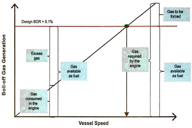
The cargo system of an LNG carrier is designed for a specified BOR, typically 0,10 to 0,15 % of the cargo volume per day during the loaded passage. The design BOR, BOG generation and the vessel speed are related as shown in Figure 1.
While other sectors of commercial shipping had moved on to the greater propulsion efficiencies of diesel engines, the steam turbine was the traditional propulsion system used for LNG carriers. To generate steam, BOG generated during the course of an LNG carrier voyage can be burned in a steam vessel’s boilers as readily as fuel oil. Steam propelled vessels are also able to handle any excess cargo BOG by dumping surplus steam to the seawater cooled condenser in the engine room. This capability means that low propulsion system loads pose no undue problems. It also removes the need for expensive ancillary equipment, such as reliquefaction plants and GCUs. In addition, turbines have proved to be extremely reliable throughout the history of LNG carrier operations and they have low maintenance requirements.
Read also: Contingency Plans for Liquefied Natural Gas Carrier
Technological advances (for using BOG as fuel directly in diesel engines) and the drive to reduce exhaust emissions and improve efficiencies have resulted in the industry using diesel engine alternatives to steam propulsion.
A comparison of general propulsion plant thermal efficiencies is provided in Table 1.
| Table 1. General propulsion plant thermal efficiencies | |
|---|---|
| Alternative | Approximate Overall Plant Thermal Efficiency (%) |
| Conventional steam turbine | 30 |
| Steam turbine with reheat | 34 |
| Dual fuel diesel engine | 38 |
| Combined cycle gas turbine | 42 |
| Slow speed diesel with reliq | 42 |
| Slaw speed diesel with gas injection and reliq | 45 |
At the publishing date of this edition, several orders have been placed for LNG carriers utilising slow speed, gas fuelled, direct drive propulsion systems. Both high pressure and low pressure gas fuel supply is utilised, depending on the engine supplier. A multi-gas carrier design has been approved for using ethane as fuel. As technology advances, other gas fuels, such as LPG, are likely.
As with other ship types, propulsion system alternatives can vary greatly, from steam to diesel to gas turbine, with direct drive, reduction geared drive and electric drive as further options. The final decision usually comes down to an economic analysis although, as some ports and terminals have restrictions on gas carriers disabling propulsion systems for maintenance, resilience will also form part of the consideration. Finally, there may be gas fuel quality concerns (ie ethane purity) that need to be coordinated between the engine supplier and operational aspects of the vessel.
There are four main types of propulsion systems fitted on LNG carriers:
- Steam:
- conventional;
- ultra steam turbine (reheat);
- dual/tri fuel diesel electric:
- with and without reliquefaction and/or GCU;
- slow speed diesel (oil only):
- with reliquefaction and GCU;
- slow speed diesel (gas fuel) either with or without reliquefaction and/or GCU:
- high pressure;
- low pressure.
Only the four basic systems listed above are discussed further in the following sections. Other systems, such as hybrid (ultra steam turbine combined with a dual fuel diesel engine and an electric motor) and gas turbine designs exist but are not discussed in this publication.
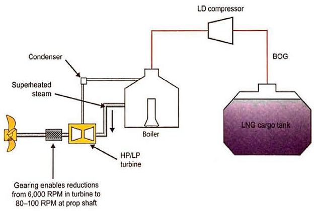
Steam
Traditional steam turbine propulsion plants operate at 60 to 70 bar pressure and 520 °C superheat steam temperature. A typical installation includes two main boilers, both of which can burn fuel oil and BOG to generate superheated steam fed to HP (high pressure) and LP (low pressure) turbines for propulsion, and two steam turbo-generators for electrical power generation. One conventional 4-stroke diesel generator is normally installed as a standby.
A single stage centrifugal type low duty (LD) gas compressor is used to supply BOG from the cargo tanks to the boilers. The plant is capable of burning fuel in any combination, such as fuel only, gas only, and any combined ratio of fuel and gas. The installation of two boilers and the steam dump system allows for proper management of tank pressures in accordance with the IGC Code.
Steam turbine propulsion plants handle excess cargo BOG by dumping surplus steam to the seawater cooled condenser in the engine room. Any shortfall of natural BOG can be replaced by forced gas (through a vaporiser) or fuel oil.
While highly reliable and simple, steam propulsion plants still have drawbacks. The overall efficiency of a traditional steam plant is the lowest of the alternatives and becomes lower as the turbine load is reduced. The efficiency of the turbo generators is even lower than the main propulsion turbine.
To enhance steam plant efficiency a reheat cycle has been introduced.

The main difference between the simple steam turbine plant and the reheat steam turbine plant is that steam is extracted from the HP turbine and sent through a reheater section of the boiler. In the reheat, the steam temperature and pressure are raised and the resultant steam is then routed to an intermediate pressure (IP) turbine. The steam pressures involved, both in the main boilers and the reheat boilers, are considerably higher, while steam temperatures are slightly higher than in the traditional, simple steam turbine plant.
Dual fuel diesel electric (DFDE)
While originally introduced as DFDE propulsion, most of the LNG carriers built with this type of propulsion plant are “tri-fuel” or TFDE, capable of burning gas, MOO or HFO. For convenience and simplicity, the term “dual fuel” will be used in this publication.
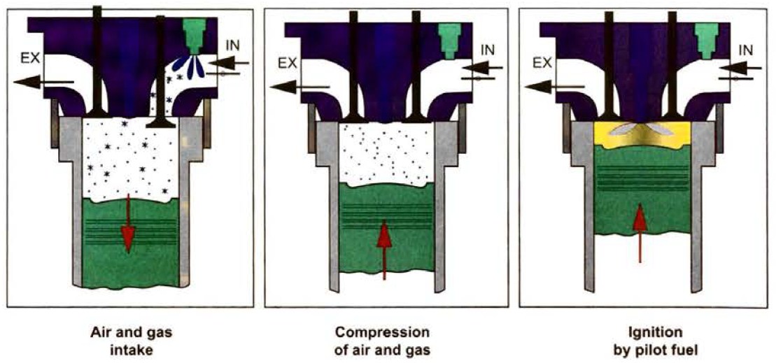
The dual fuel engine is a normal 4-stroke, medium speed diesel engine that has been adapted to burn natural gas as a fuel. It operates on the Otto cycle, where the gas is injected into the intake air supply to the cylinder. Combustion of the resulting gas/air mixture is initiated by ignition of MDO. MDO or HFO can be used to backup or augment any shortfall of BOG.
One issue with medium speed engines using the Otto cycle is that of knocking. Knocking in a 4-stroke engine occurs when the peak of the combustion process no longer occurs at the optimum moment. The methane number of a gas provides an indication of the knock tendency of the gas. It is a calculated value based on the proportion of heavier constituent gases, such as ethane, propane, and butane, within the natural gas. These heavier hydrocarbon constituents have a higher flame speed and are easier to ignite than methane and higher proportions of non-methane components will result in a lower methane number. High methane numbers mean high knock resistance.
It will be interesting: Individual Responsibilities on Liquefied Natural Gas Vessel
In the case of natural BOG, the methane number is not normally a problem as the evaporating temperature of methane (minus 162 °C (-162 °C)) is much lower than that of the heavier hydrocarbons and the natural BOG temperature is normally lower than the evaporating temperature of the heavier hydrocarbons. Forced BOG may, however, contain a higher content of heavy hydrocarbons in the gas fuel. Knocking will result in the need to reduce engine load and, if it becomes severe, will result in the engine automatically changing over to liquid backup fuel.
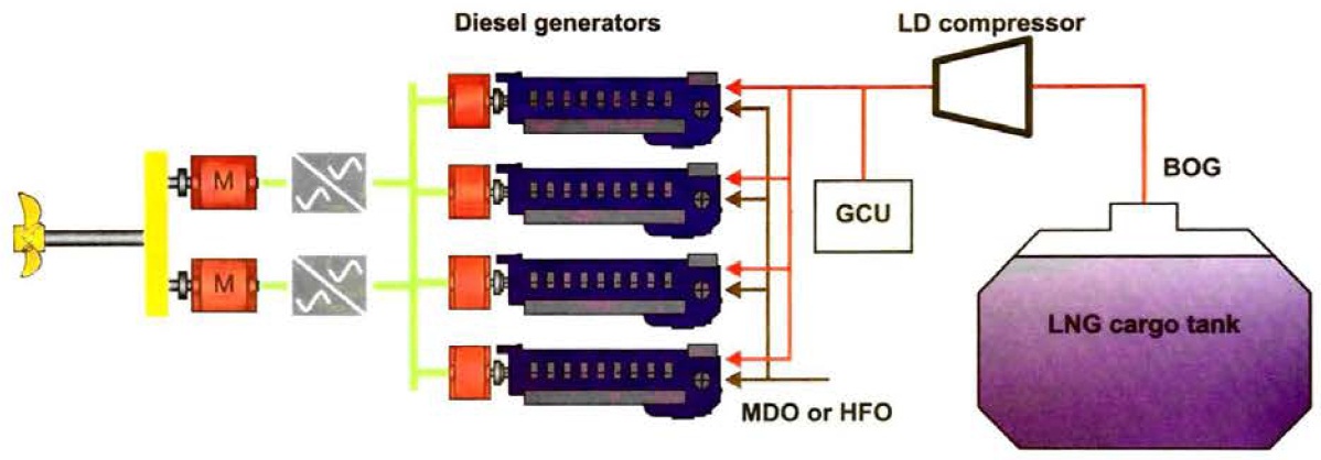
The diesel-electric components of a typical diesel-electric propulsion plant are shown in Figure 6.
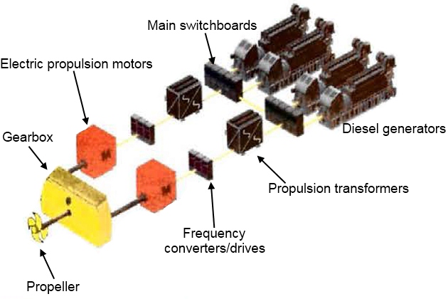
The diesel generators produce electricity for both propulsion power and for auxiliary loads and they can be located anywhere in the engine room, providing flexibility in engine room configuration. Although there may not be multiple shafting and gearbox arrangements, there are multiple diesel generator sets so some level of redundancy is provided in the design.
The diesel-electric propulsion takes advantage of the efficiency of high voltage distribution systems and the design uses 6,6 kV instead of the more traditional 440 V generation systems. The total installed power on DFDE ships is lowest of the alternative propulsion systems, as the generators are used more efficiently in port (ie high discharge loads) and at sea.
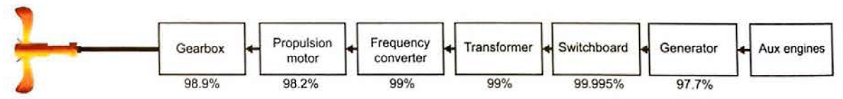
While the overall efficiency of a diesel-electric plant is higher than a simple steam propulsion plant, there are some drawbacks. By virtue of design, there are higher losses through the drive train of a diesel-electric plant than through a direct drive design (which is normally in the order of 1 %).
Slow speed diesel (oil fuel)
This propulsion system is identical to those in use on most of the commercial merchant fleet; 2-stroke slow speed diesel engines with direct drive coupling to the propeller shaft. Auxiliary electrical load is typically provided by 4-stroke diesel generators. To manage tank pressures a reliquefaction plant is installed, along with a GCU.
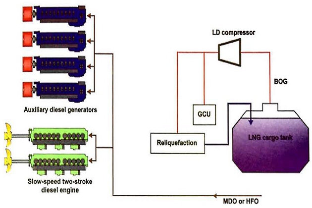
While the overall propulsion system is, therefore, simplified and somewhat “standard“, the reliquefaction plant does introduce some complexity to the overall ship design.
Slow speed diesel (gas fuel)
2-stroke diesel engine technology has advanced to a point where it is now possible to reliably use gas as a fuel. The advantages of this propulsion option include the higher efficiency of a slow speed diesel engine coupled with direct drive, and the flexibility of fuel supply. Pilot and backup fuel can be HFO or MDO.
There are two alternatives for gas fuel in a 2-stroke engine. One uses higher pressure gas injection, sometimes referred to as ME-GI. The other uses lower pressure gas supply, similar to that of the dual fuel plant described earlier in this section, which is referred to as 2-stroke X-DF.
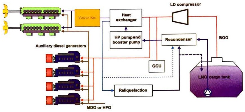
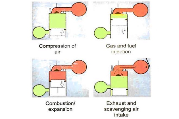
The first alternative is to inject the gas fuel directly into the combustion chamber, along with a small amount of liquid pilot fuel, with the subsequent combustion process following the diesel cycle. It requires gas fuel pressure in the order of 250 bar to introduce the gas fuel into the compressed scavenging air.
The higher gas pressure required can be supplied via either a compressor or a high pressure fuel pump/vaporiser unit.
Given the higher fuel gas pressures utilised in the ME-GI design, a risk assessment and gas dispersion study for the high pressure gas system in the engine room is recommended. Although the probability of gas leakage may be regarded as low, the severity of the consequences of a leak are high.
2-stroke DF engines
These designs utilise lower pressure gas, in the order of 10 to 15 bar, with a gas fuel system similar to dual fuel 4-stroke propulsion plant designs. As with the 4-stroke designs, the lean burn combustion process follows the Otto cycle.