This article covers the weld processes, failures and weld testing techniques, like Non-Destructive Testing (NDT), Magnetic Particle Inspection (MPI), Dye Penetrant Inspection (DPI) and others.
Weld failures – the need for regular weld inspection and non-destructive inspection techniques
Introduction to weld failures
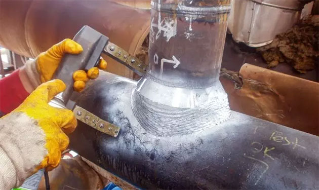
When steel structures are fabricated, the most common method of joining the steel components together is by welding. Consequently, the need for welds that are of good quality and properly applied is of great importance.
There are many types of welding processes, including:
- Electrode (stick);
- Manual Inert Gas (MIG);
- Tungsten Inert Gas (TIG);
- Brazing techniques using oxyacetylene gas.
The reasons why welding is a favoured method of joining steel components together is because it is speedy and efficient and results in a joint which has strength and is usually reliable, although there are exceptions to this reliability factor which we shall discuss later in this article.
When a weld is being formed, certain chemical and metallurgical actions take place in the metal adjacent to where the weld is being deposited. Understanding what these actions are, and how it will affect the final construction, is part of the welder’s initial consideration in designing the weld and choosing the correct welding process for a particular job.
These chemical and metallurgical actions are complex in themselves, but with the added influences such as personal welding techniques, potential contamination, influx of moisture and air movement around the weld, to name but a few, it’s not surprising that welds occasionally fail.
Most weld failures can be attributed to:
- Improper design of weld joint;
- Poor selection of base materials and filler materials;
- Inappropriate welding processes;
- Residual stresses;
- Ineffective or non-existent inspection procedures;
- Welded components operating outside their safe parameters.
Types of weld failures – cracks
Cracks are a significant element in weld failure. This is because the crack has the potential to grow into a total failure once the weld is under load conditions.
There are a number of reasons why a crack will present itself within a weld. These include poor welding technique, faulty welding equipment and poor joint design. Furthermore, there can be porosity within the weld, or even an amount of slag which can encourage cracks to develop.
Finally, the welding operation itself introduces stress in the vicinity of the weld, with intense localized heating which causes expansion and contraction that can itself cause cracking.
Hot cracks and cold cracks
Cracks in welds can be classified into two types, hot cracks and cold cracks. This refers to the condition of the weld when the crack first presents itself.
Hot cracks, as the name suggests, develop when the weld is still at a high temperature. Initially, they propagate between the grains of the weld material whilst it is still molten and develop into a full crack during the solidification process.
Cold cracks develop at low temperatures, generally because of stresses which develop as the weld solidifies. The influx of hydrogen during the weld process can also have an embrittling effect (loss of ductility) which can encourage cold cracking.
Cold cracks are also known as delayed cracks.
Porosity
Weld porosity is the presence of air bubbles within a weld. If seen through a microscope, the surface of a weld which suffers from porosity would be full of holes. However, those holes are not only on the surface, but they are likely to continue throughout part or even the whole of the weld.
Porosity is a weakening factor in a weld’s integrity. If a weld has been designed at the outset to work within certain parameters, then it is indeed possible that an unexpected weld failure will occur under normal working conditions if porosity within a weld is not recognized before the component goes into service.
Read also: Types of Failure Modes that may lead to Loss of Containment from Hydrocarbons
Porosity happens when the molten weld pool absorbs certain gases (nitrogen, oxygen or hydrogen) which become trapped and result in tiny bubbles once the weld solidifies. The main reason for this absorption is poor gas shielding during the welding process. Gas shields can also be contaminated by draughts of air around the welding process which can break through the shield and introduce any of the alien gases to the weld process, resulting in porosity.
Contamination from hydrogen – which stems from moisture – can be attributed to moisture being present on the electrodes, the fluxes or the components being welded.
Weld profile
Weld profile refers to the size of the weld.
Weld profiles can have a significant influence on the integrity of a weld. If a weld is too small in section, then its load carrying capability will be limited and may well not meet the parameters expected of the finished component.
However, if a weld is too big this can also create problems which may lead to a weld failure. Too much root penetration, which is associated with welds regarded as too big, can create defects and cracks. Excessive weld profiles can also distort components to the extent that if those components are subject to a compressive load when put into service, they could buckle under the strain.
Weld testing techniques
Weld testing techniques – Non-Destructive Testing (NDT)
Given that there are so many factors which can affect the integrity of a weld, it makes sense to use a system of inspection and/or testing at appropriate points in time to ensure any defects are detected before they manifest themselves in a failure. The use of Non-Destructive Testing (NDT) has proved to be a valued procedure in reducing the number of weld failures occurring on components which are in service.
As we’ve just mentioned, NDT should be conducted at appropriate points in time, those being:
- Once the component has been fully fabricated to ensure the welds do not have unacceptable defects;
- On a regular basis during the service life of the welded component to ensure that no unacceptable defects have developed since fabrication or since the last non-destructive testing was conducted.
There are a number of non-destructive testing methods that can be used.
These include:
- Magnetic Particle Inspection (MPI);
- Dye Penetrant Inspection (DPI);
- Ultrasonic flaw detection;
- Radiography testing.
We will now look at each of these methods in more detail.
Weld testing techniques – Magnetic Particle Inspection (MPI)
Magnetic Particle Inspection (MPI) is a non-destructive testing process which can detect surface or near sub-surface defects in ferrous metals. It does this by first of all putting a magnetic field into the material about to be tested. Once this has been done, ferrous iron particles, which have previously been coated in a fluorescent dye, are introduced to the magnetized area.
Source: flyability.com
Where a surface or sub-surface abnormality (defect) exists, the magnetic flux will leak out, allowing the iron particles to be attracted to that location. This is known as an indication. At this point in the testing process, an ultraviolet light is shone onto the area being tested and this illuminates the fluorescent-coated particles, which indicates the magnetic flux leakage caused by the presence of a defect. The defect can then be analysed as to its severity and what action, if any, is required to rectify the situation and avoid a failure.
Weld testing techniques – Dye Penetrant Inspection (DPI)
Dye Penetrant Inspection (DPI), also known as Liquid Penetration Inspection (LPI), or Penetrant Testing (PT), is a low-cost, non-destructive testing process which can detect surface-breaking defects in non-porous materials. The principle behind the process is that dye will penetrate into any surface-breaking defect and highlight it.
Because of its relative low cost, it is an effective way of detecting defects in a wide range of components which are in service, as well as newly constructed fabrications.
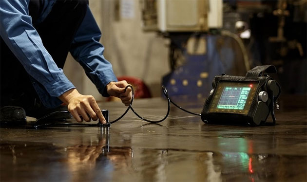
Weld testing techniques – ultrasonic flaw detection
Ultrasonic flaw detection is a non-destructive testing process which uses energy waves (high frequency vibrations – ultrasound) to read the exact structure of a component and thus detect any flaws or defects that may be present.
Its main advantages are:
- It can detect defects which are deep inside any component;
- It can detect very small defects;
- It offers a greater accuracy of analysis than other non-destructive testing systems;
- In certain circumstances, the size, shape, orientation and location of the defect can be established;
- The procedure is non-hazardous.
However, there are some disadvantages, which include the fact that the operator has to be highly trained and experienced not only to operate the equipment effectively, but also to fully understand the readings from the test procedure, which are displayed in a spiked graph form. Also, components which are irregular in shape, are very thin or have a rough surface can be difficult to analyse.
Weld testing techniques – radiography testing
Radiographic Testing (RT) is a non-destructive testing process which uses short-wavelength electromagnetic radiation to penetrate the material being inspected and highlight any defects.
This electromagnetic radiation is emitted from one side of the component and detected and measured on the opposite side of the component. This allows an analysis of the composition of the material to be made. This is usually in the form of a film or negative (X-ray).
Source: Amparo Engineering Limited
However, developments in this form of Non-Destructive Testing (NDT) have evolved into real time radiography. This is where images are reproduced on a monitor screen and can be displayed live as a positive image rather than as a negative X-ray image.
Safety controls and measures when conducting radiography testing processes
Radiography testing involves using intense radiation sources which can expose people who conduct the testing, as well as those in the vicinity, to significant amounts of radiation. Consequently, radiography testing should be conducted under a permit-to-work system which sets out the control measures to be put in place and the checks that must be carried out.
Prior to the work commencing, a Risk Management Techniques used in the Oil and Gas Industriesrisk assessment should be conducted. This should include considering the possibility of a radiation accident occurring and how it can be prevented, or how the consequences can be mitigated by establishing emergency procedures and designating an appropriate person to administer them if needed.
If the testing is to be conducted on readily movable components, this should be done in an adequately shielded enclosure or cabinet. Conducting radiography in this way should always be the first choice wherever possible.
Where it is not possible to place the components to be tested within a shielded enclosure or cabinet, such as onsite fabrications, personal exposure and risks should be controlled by using local shielding, safe systems of working, and applying Radiation Controlled Area designation.
There may also be local regulations regarding giving notice to enforcing authorities that radiography testing is being conducted.
Those conducting the testing should use dose rate monitoring instruments so they can confirm that sealed sources of radiation have fully retracted into their containers once the testing has concluded, or that X-ray sets have stopped emitting radiation. In addition, the use of personal electronic alarming dosimeters can give immediate warning of high dose rates, but these should be used only as an addition to dose rate monitoring and not as an alternative.
REVISION QUESTIONS FOR ELEMENT 3 CONTINUED
Answer 1
- Magnetic Particle Inspection (MPI);
- Dye Penetrant Inspection (DPI);
- Ultrasonic flaw detection;
- Radiography testing.