There is a wide range of materials used in the construction of facilities in the oil and gas process industry, the majority of which are steels of varying grades and types, although plastics are also extensively used, especially for the storage of hydrocarbons. These facilities include offshore rigs, onshore refineries and storage facilities.
- Introduction and terminology
- Introduction
- Tension
- Compression
- Tension and compression
- Shear
- Properties of materials
- Failure modes
- Introduction
- Creep
- Stress
- Stress corrosion cracking
- Thermal shock
- Brittle fracture
- What is meant by a safe operating envelope
- Use of knowledge of failure modes in initial design, process and safe operating procedure
- Failure of the annular rim (bottom rim of storage tank)
- REVISION QUESTIONS FOR ELEMENT 3
Introduction and terminology
Introduction
The properties required of materials to cope with the wide variation of conditions can be extensive, and the process of considering which material is best for any given situation is a complex one. Consequently, understanding how certain conditions will affect any material in a given situation and then applying the most appropriate material to that situation is the ideal approach.
The first step in this approach is to understand the different ways in which the failure of materials can occur and what controls can be put in place to counteract these failures.
First of all, we will look at some of the terms and phrases used in relation to forces to which materials can be subject and what they mean.
Tension
Tension – sometimes referred to as tensile force – is a force which is acting in two opposite directions. It could also be described as trying to stretch the material or pull the material apart.
An example would be a chain being used by a crane to lift a heavy load.
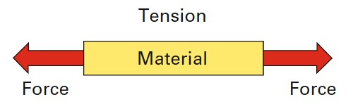
Source: Wise Global Training
All materials have a breaking point, and if we take our example and say the load lifted by the crane was greater than the threshold of the material the chain was made from, it will fail (break).
Compression
Compression force is the opposite of tension in that the material is being compressed by pressure. An example might be the legs of an offshore rig mounted on the seabed. The legs carry the weight of the rig and transfer this weight to its standpoint on the seabed.
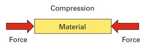
Source: Wise Global Training
Most materials will compress to some extent when pressure is applied. However, if the pressure exceeds the characteristic threshold of the material, given its current dimensions, the forces will have to be dissipated in some way. Again, using our example of legs on an offshore rig, if the rig was exceptionally loaded, the pressure would likely be dissipated by the legs buckling.
Tension and compression
We have covered tension and compression but under certain conditions, these two forces can be applied to one piece of material at the same time.
For example, if a bending motion is exerted on a steel bar, this creates both tension and compression forces within the bar.
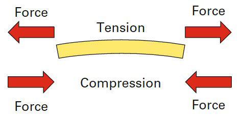
Source: Wise Global Training.
A practical example of this is a steel beam suspended between two points which is carrying the weight of a piece of machinery.
Shear
Shear is where two forces are being applied to a material but in opposite directions (see diagram).
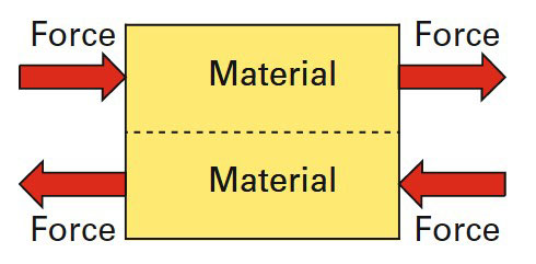
Source: Wise Global Training
The shear force acts on the dotted line in our diagram as if it is trying to tear the material apart.
Properties of materials
Now we’ve looked at some forces which materials can be subject to, we should now look at properties of materials. Each material has its own properties, and understanding what these properties are will help us understand which materials are best applied to specific situations.
Properties of materials – ductile
A material which is ductile is one which can be subjected to tensile forces without it fracturing. An example of this is where a wire is drawn through an extrusion die.
Properties of materials – malleable
A material which is malleable is one which can have its shape changed without it cracking. This could be through compression (hammering) or by bending. Lead, tin and copper are all malleable materials.
Properties of materials – brittleness
A material which is brittle is one which has no plastic deformation characteristics. This means that if a force is applied which exceeds its characteristic threshold, it will crack or shatter with very little deformation. If the broken pieces were then brought back together, they would fit almost perfectly, much like a jigsaw.
Cast iron is an example of a brittle material.
Properties of materials – elasticity
A material which has elasticity is one which can resume its former shape or dimension after a deforming force is applied and then released.
All materials, if they have the characteristic of elasticity, have a limit to how much force can be applied before permanent deformation enters the equation. If this limit is exceeded, the molecular structure of the material changes and the new shape becomes a permanent feature.
Failure modes
Introduction
Now we have had an introduction to some of the forces materials can be subjected to and some of the properties of materials, we can turn our attention to various failure modes experienced by materials used in the oil and gas industry.
The failure modes we shall be looking at are:
- Creep;
- Stress;
- Stress corrosion cracking;
- Thermal shock;
- Brittle fracture.
Creep
Creep is where a solid material is subject to long term exposure of high stress levels and gradually deforms in shape or dimension. Creep is exacerbated when the material is also subjected to heat for long periods of time. Most cases of creep are insignificant but in certain situations, the amount of deformation may be unacceptable and may lead to failure of the component.
Control and monitoring of creep
The main control measure in managing or preventing creep is applied at the design stage of any facility. Process design should specify the use of appropriate materials in all situations which have the tolerances adequate for the expected parameters to which they will be exposed.
At the stage where the materials are in use within the process or application for which they were acquired, these parameters should be made known to the operators and should not be exceeded so that creep does not occur, or is kept within acceptable limits. Over and above these control measures, regular maintenance checks and inspections should be conducted.
Source: Mee-Inc
If the processes are complex and/or the consequences of failure due to creep are significant, then more in-depth non-destructive checks may be appropriate, such as ultrasonic methods or the continuous monitoring of vibration.
There are certain situations where creep is a well-known Risk Management Techniques used in the Oil and Gas Industriesrisk factor, such as water tubes in boilers and furnaces. In these cases, a creep failure would present itself as a rupture of the water tube.
In these cases, monitoring and controlling tube metal temperatures is the ideal control measure. However, where super-heater and reheat super-heater water tubes are used, creep is a factor that can only be controlled by scheduled replacements of the tubes within their predicted life expectancy.
Stress
Stress is created when a load is applied to a material.
For example, a girder carrying the weight of a piece of machinery is under stress due to the weight of the machine.
Where heavy weights or loads are involved, there may be some visible deflection or movement, but this may be part of the design.
Stress can be described as “the load divided by the cross-section area”:
newtons ÷ m2
Stress can occur during normal operations.
For example, where components are subjected to warming and/or cooling, this will lead to those components expanding or contracting.
It is essential that these movements and variations in sizes of these components are allowed for at the design stage, otherwise stress can be created at critical points such as anchor bolts and welds.
Stress is often built into components inadvertently during the manufacturing process, especially when welding has been part of that process or where components are bolted together, and especially when they have been forced into position.
On pipework which has been welded, stress is often unavoidably introduced due to the application of heat during the welding process.
However, these stresses can be mitigated to some extent by allowing the pipework, once it has been welded, to remain at a controlled temperature for a specific period of time by wrapping ceramic blankets around the pipework and then gradually reducing the temperature in a controlled way. This allows the pipework to find its natural configuration, which has the effect of reducing the stress levels introduced by the welding process.
This method of introducing measures that allow stress to dissipate naturally after components have been welded together is called Post Weld Heat Treatment (PWHT).

Source: Metallurgyfordummies
It is generally applied where the standards or codes of construction demand that inbuilt stresses must be reduced to an acceptable level, for example as in pressure vessels.
Post weld heat treatment involves heating the steel, immediately after welding has been completed and before it starts to cool, to a temperature dictated by the particular type of steel used, but this is generally around 230 °C. This temperature is held for a period of time dictated by the thickness of the material, but in line with 1 hour for every 25 mm of thickness. The steel is then allowed to cool gradually under controlled conditions.
There is another, similar stress reducing treatment, called stress relief heat treatment, which is used on larger structures where the stresses have been built in as the structure has been constructed, and where the stresses are widely dispersed throughout the structure. In this case, the whole structure is heated to a temperature dictated by the particular type of steel used, but it’s generally around 650 °C. This temperature is again held for a period of time dictated by the thickness of the material, but in line with 1 hour for every 25 mm of thickness. The steel is then allowed to cool gradually under controlled conditions.
The effect of both these treatments is to introduce conditions to the component or structure where residual stresses are allowed to relax and dissipate.
Stress corrosion cracking
Stress Corrosion Cracking (SCC) is where a material is subjected to both stress and corrosion. The corrosion has the effect of reducing the threshold of the material at a particular point (i. e. it weakens it), resulting in the stress causing the material to crack at that point. If the material had been subject to stress without corrosion, the crack would not have occurred. If the material had been subject to corrosion without stress, again, the crack would not have occurred. It is where these two factors combine that stress corrosion cracking can occur.
The environment can play a big part in introducing corrosion.
For example, offshore facilities are subject to salt water as well as severe weather conditions.
Cleaning can introduce chemicals which can be corrosive. Carbon steel pipework, which is lagged, may be subject to sweating.
Typical stress corrosion cracking failures occur in:
- pressure vessels,
- pipework,
- highly stressed components
- and in systems when a deviation from normal operating conditions or the environment occurs.
SCC can be highly chemical-specific and some alloys can undergo SCC after a few exposures to a specific chemical environment. The surface of the material can appear bright and shiny whilst inside the material many microscopic cracks may be present. Consequently, SCC can lead to sudden and unexpected failure with possible catastrophic consequences.
Because stress corrosion cracking can be so highly chemical-specific, certain pairings of materials with specific environments should be avoided.
These include:
- Brass paired with ammonia;
- Stainless steel paired with chlorides;
- High strength steel paired with hydrogen.
The following controls will help in the prevention of stress corrosion cracking:
- Selection of appropriate material;
- Controlling service stress;
- Use of corrosion inhibitors;
- Coating material;
- Isolating material from the local environment.
Thermal shock
Thermal shock is the stress introduced into a material as a result of a sudden and dramatic change in temperature. The result is that the thermal gradient of the affected area of the material is uneven, causing stress within the material. The temperature change causes the molecular structure of the material to expand, but as this expansion is not uniform, the bonds which hold the molecules in formation are weakened, which may lead to a failure (crack) in the material.
An everyday example of thermal shock would be if boiling water is poured into a glass jar. Inevitably, the glass jar breaks, and this is because the molecular structure on the inside of the glass expands more rapidly than that on the outside of the glass.
Let’s look at an example of where thermal shock might occur. Superheated steam introduced into cold pipework would cause thermal shock on the pipework by expanding the inner surface of the pipes rapidly, whilst the outer surface would expand more slowly. This would create the possibility of cracks occurring in the pipe material when the strength of the material is overcome by the stresses of differing expansion rates. Furthermore, flanged joints may start to spring because the sections of pipework are expanding at different rates, and leaks may occur quite suddenly.
Expansion in pipes can be expected under normal operating conditions as well as exceptional circumstances such as the example just quoted. In order to prevent the critical effects of expansion on steam pipework, it is normal to design in expansion loops in order to allow the pipes to expand without building up stresses and strains at flanged joints. You can clearly see these loops (the U-shaped configuration) in the pipes on the right of the photograph in Figure 7.
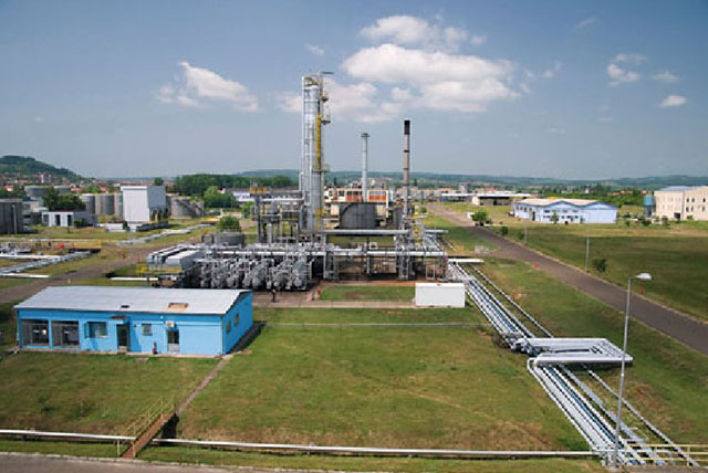
Source: iStock.
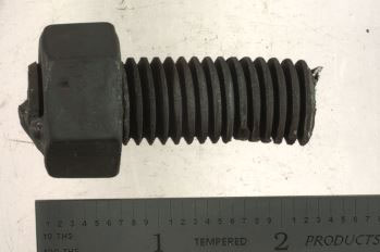
Expansion bellows are also used to prevent the critical effects of expansion. These are fitted directly into the pipework allowing the bellows to expand and contract, thus reducing the effects of expansion on the pipework and material.
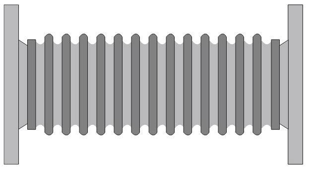
Source: Wise Global Training.
Other means of reducing thermal shock would be to:
- Change the temperature more slowly;
- Change the temperature more evenly;
- Increase the thermal conductivity of the material;
- Reduce the material’s coefficient of thermal expansion;
- Increase the material’s strength.
Brittle fracture
An example of brittle fracture would be if someone tried to bend an engineering file, which is made of a very hard but brittle metal, it would snap. There would be little or no permanent deformation and the broken pieces of the file could be offered together in near-perfect alignment.
However, under certain circumstances low carbon and medium carbon steels, which are used widely in the petrochemical industry and which are normally considered to have ductile properties, can also be subject to brittle fracture.
The conditions where low and medium carbon steel can be affected by brittle fracture are as follows:
- A stress concentration must already be present in the steel. This may be a welding defect, a fatigue crack, a stress corrosion crack or a designed notch such as a sharp corner, a threaded hole or something similar;
- A tensile stress must be present. The tensile stress must be of a magnitude sufficient to cause deformation;
- The temperature must be relatively low for the steel concerned;
- Susceptible steel has been used.
The absence of any one of the above conditions will reduce the possibility of brittle fracture occurring.
Brittle fracture in normally ductile steel has caused many unexpected failures in the past, with some resulting in catastrophic consequences. Part of the reason for this behaviour is that it is not always necessary to have high stresses present for failure to occur. Brittle fracture can occur solely because of residual tensile stresses.
Brittle fracture of normally ductile steels occurs primarily in box-like structures such as box beams, tanks and pipes, particularly where their construction has involved welding.
What is meant by a safe operating envelope
A safe operating envelope is defined as the parameters and conditions a plant must operate within to ensure it is not subjected to excessive stress which might introduce or encourage failure modes. These parameters and conditions will be clearly set out in the operating procedure document. Any changes and adjustments to a process must remain within this safe operating envelope in accordance with normal operating procedures.
Some examples of parameters and conditions include:
- Safe working loads;
- Maximum flow rates;
- Maximum pressures;
- Maximum and/or minimum temperatures.
There are conditions, usually external environmental conditions, where a process has the potential to be operated outside of its safe working envelope. These include high wind speeds, sea state, lightning, etc. In these cases, the process may have to be shut down until conditions return to normal.
An example of a situation where parameters can be exceeded by adverse factors is as follows. A gas compressor unit is compressing gas in order to push it through a pipeline. Whilst the gas is moving forward, the equipment is within its safe working envelope. However, a discharge valve fails shut and the gas compressor unit goes into a condition known as “surge”. This is where the compressor unit cannot move the gas forward through the outflow side so it tries to pump the gas through itself to the inflow side. The gas compressor unit is now outside its safe working envelope and is likely to destroy itself, with potential catastrophic consequences.
Read also: All you need to know about Process Safety Management in Liquefied Petroleum Gas Industry
In order to counteract this particular scenario, it is necessary to anticipate this kind of event at the design stage, usually at the Hazard and Operability study (HAZOP) stage of development. In this particular scenario it would be possible to design into the process anti-surge valves and a bypass system which would allow the compressor to recirculate the gas without adverse effects until an operator could reset the process.
Use of knowledge of failure modes in initial design, process and safe operating procedure
Previously, we have discussed how failure can be introduced at the design and/or the manufacturing stage of a process plant. We have also discussed different failure modes, and finally we have discussed what the consequences of operating outside a safe operating envelope are.
Consequently, it can be seen that because these elements of failure may well lie unseen within the process plant, it is important that when the plant is in operation, it remains within the parameters of the plant that were set at the design stage.
At the very outset it is possible to ensure parameters are designed into the plant, which give the plant safe margins of operational limits.
When plant is being designed, careful thought and consideration should be given to the process itself and the extent of stresses that may be encountered in extreme circumstances and how these stresses might be controlled.
Some simple control techniques include:
- Fitting expansion loops and expansion bellows in steam pipes. We showed examples of these earlier;
- Ensuring the materials used are correct and capable of coping with the conditions they will be exposed to;
- Ensuring the thicknesses of the materials used are adequate to cope with the stresses they will be exposed to;
- Ensuring the strength of materials used is adequate;
- Ensuring equipment is correctly supported;
- Ensuring pipework and machinery is correctly aligned;
- Automatic shutdown trips are set to activate where parameters are exceeded;
- Ensuring the control systems are adequate;
- Having operating procedures to hand.
Failure of the annular rim (bottom rim of storage tank)
The bottom plate in a storage tank is known as an annular plate and the junction between this bottom plate and the wall of the storage tank is known as the annular rim. The annular plate usually sits on a foundation of hard-core or a concrete ring wall, and is joined to the walls of the tank. Although the annular plate is not subject to high levels of stress, the joint of the plate to the walls is. This is because the weight of the product within the tank wants to push the walls outwards whilst at the same time push the annular plate downwards. This creates a high level of bending stress. The quality of the foundations will have a bearing on the downward deflection of the annular plate.
A further complicating factor to this stress is the fact that annular plates are prone to corrosion attacks both on the outer side where the tank shell sits on the annular rim and on the underside of the annular plate where trapped water may lie undetected. This corrosion, coupled with the prolonged stress, can lead to stress corrosion cracking and failure occurring without warning.
REVISION QUESTIONS FOR ELEMENT 3
- Explain what stress corrosion cracking is and under what circumstances it might be encountered;
- Define what a safe working envelope is;
- Many fixed and floating roof storage tanks have annular rims:
- Outline what an annular rim is;
- Explain what problems can be associated with annular rims.
Answer 1
Stress corrosion cracking is where a material is subjected to both stress and corrosion. The corrosion has the effect of reducing the threshold of the material at a particular point (i. e. it weakens it), resulting in the stress causing the material to crack at that point. If the material had been subject to stress without corrosion, the crack would not have occurred. If the material had been subject to corrosion without stress, again, the crack would not have occurred. It is when these two factors combine that stress corrosion cracking can occur.
Answer 2
A safe operating envelope is defined as the parameters and conditions a plant must operate within to ensure it is not subjected to excessive stress which might introduce or encourage failure modes.
Answer 3
The bottom plate in a storage tank is known as an annular plate. The annular plate usually sits on a foundation of hard-core or a concrete ring wall, and is joined to the walls of the tank. This junction between this bottom plate and the wall of the storage tank is known as the annular rim.
Answer 4
The joint where the annular plate and the tank walls meet (the annular rim) is subject to constant stress. This is because the weight of the product within the tank wants to push the walls outwards whilst at the same time push the annular plate downwards. This creates a high level of bending stress. The quality of the foundations will also have a bearing on the downward deflection of the annular plate.
A further complicating factor to this stress is the fact that annular plates are prone to corrosion attacks both on the outer side where the tank shell sits on the annular rim, and on the underside of the annular plate where trapped water may lie undetected. This corrosion, coupled with the prolonged stress, can lead to stress corrosion cracking and failure occurring without warning.