Learn about the advantages and applications of High Duty (HD) compressor in LNG carrier cargo systems. Explore how these specialized compressors optimize LNG transportation efficiency and safety.
Reference: SIGTTO “LNG Shipping Suggested Competency Standards”, Sections:
1 Have an awareness of their purpose and operating principles.
2 Know and understand design features:
- blower;
- driving mechanisms;
- capacity control mechanisms;
- shaft sealing arrangements;
- bulkhead sealing arrangements;
- principles of operation and purpose of surge control.
3 Know and understand operational requirements and procedures:
- setting up:
- nitrogen sealing;
- lubrication.
- automatic control requirements;
- starting of 2nd compressor;
- shutdown.
4 Know and understand their alarm settings and resulting actions.
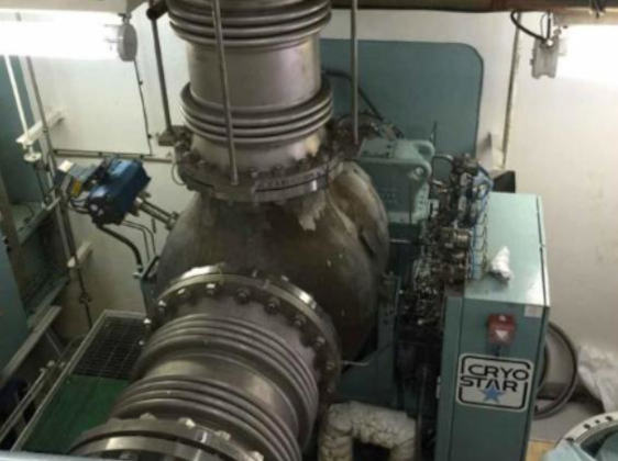
Two high duty (HD), equally sized electric motor driven centrifugal compressors are installed in the compressor room on deck. They are provided for handling and returning ashore the LNG cargo vapours created during cooldown and cargo loading. This keeps the cargo tank pressure within accepted limits.
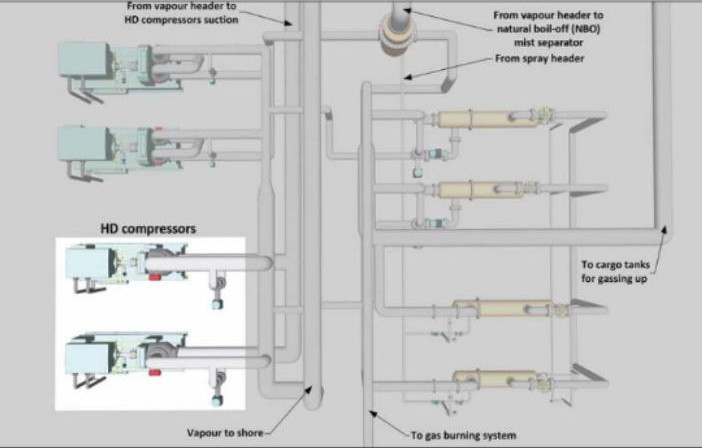
HD compressors are used for pressurisation of a Cargo System – Tank ConstructionMoss cargo tank if an emergency discharge is necessary, because the pumps in the cargo tank would not be available. Gas is discharged through the vapour header into the top of the cargo tank, where the resulting pressure in the tank forces any liquid out via the liquid loading pipe.
| HD Compressor/Typical Details | |
|---|---|
| No. stages | single stage motor driven |
| Capacity | 34 000 m3/h |
| No. on board | 2 |
| Suction temperature | minus 140 °C (-140 °C) |
| Discharge temperature | minus 105 °C (-105 °C) |
| Suction pressure | 1,0 bar |
| Discharge pressure | 2,0 bar |
| Power | 455 kW |
| Shaft speed | 11 200 rpm |
| Capacity | 6 600 V, 198 A, 1 095 kW |
| Motor speed | 3 580 rpm |
The compressors must be suitable for both vapour return duties and warming-up duties and be able to handle methane vapour, IG or mixtures of both. Undersized compressors will lead to extended cargo handling times, particularly in the case of cooldown. For both duties it may be assumed that the maximum capacity can be met by running both compressors in parallel.
A typical HD compressor has the following characteristics:
| Type | Centrifugal. Single stage. Fixed speed with adjustable guide vanes. |
|---|---|
| Volume flow | 33 980 m3/h |
| Inlet pressure | 1 030 mbar |
| Outlet pressure | 2 000 mbar |
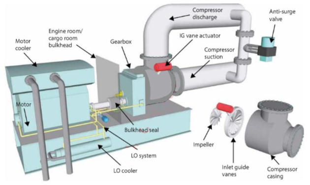
Driving mechanisms/shaft sealing arrangements
The HD/LD compressors are driven by electric motors that are installed in an electric motor room and segregated from the compressor room by a gas-tight bulkhead. The shaft penetrates the bulkhead with a gas-tight shaft seal.
The compressors are operated locally or remotely from the IAS in the cargo control room (CCR).
Capacity control mechanisms
The capacity of each should be based on the need to achieve the times specified for evaporating the unpumpables (liquids remaining after “heel out”) and warming up.
Each compressor will have an independent automatic anti-surge control and safety system. The compressors and associated control systems should be designed to ensure stable operation in parallel.
Suction flow control
To achieve the required gas flow, the compressors have inlet guide vanes fitted at the suction end. The vanes are operated by a pneumatic actuator, that receives control signals from the suction flow controller in the IAS. The vanes can be rotated from an approximate angle of minus 30° to +80°. The position is indicated on both local and remote panels
The operator should be able to adjust the gas flow rate according to the desired vapour header pressure.
A control system may be provided for the suction flow control of each high duty compressor and the process value (PV) of the flow controller is compensated according to the temperature and pressure variation.
Bulkhead sealing arrangements
The motor should be installed in the adjacent motor room and should drive the compressor via an intermediate shaft that penetrates the bulkhead through a gas-tight gland.
The motor, gearbox and compressor should be mounted on a common bedplate that incorporates the gas-tight gland and partial bulkhead, with the whole installation designed to minimise vibration.
The seal gas system is provided to prevent lube oil (LO) mist from entering the process stream (compressed LNG vapour) and to avoid cold gas flow into the gearbox and into the LO system. Seal gas is N2 produced by the Nitrogen Generator System on Liquefied Natural Gas Carriersnitrogen generators on board.
After a period of ~ 7 days of non-operation, the unit must be purged with dry warm N2. There is an interlock fitted so that the nitrogen generator cannot be started with the seal gas system inhibited.
Principles of operation and purpose of surge control
An automatic surge control system is provided to ensure that the compressor flow rate does not fall below the designed minimum during start-up and steady state operation. Below this rate, the gas flow will not be stable and the compressor will be liable to surge, causing shaft vibration that could damage the compressor.
Both HD compressors are equipped with an automatic surge control system that consists of:
- a flow transmitter;
- differential pressure transmitter;
- a ratio station;
- an anti-surge controller;
- a surge control valve on the gas stream.
On the basis of a preset ratio between the gas flow and compressor differential pressure signals, the anti-surge controller produces a signal that modulates a compressor surge control valve.
Setting up nitrogen sealing lubrication
Bulkhead seal and lube oil (LO) system
The seal gas is injected into the carbon ring with back-up “labyrinth type” seals between the gearbox shaft bearing and the compressor wheel. The system is maintained by a pressure control valve, where seal gas pressure is always higher than the suction pressure (usually adjusted at 300 mbar).
LO in the system is stored in a vented LO sump (typically 400 litres). An integrated steam immersion heater with a thermostatic temperature control valve will be fitted in the sump. This maintains a constant temperature and avoids condensation when the compressors are stopped, so the heater will automatically switch off if the LO temperature reaches +25 °C. The auxiliary LO pump will not operate when the LO temperature is below +15 °C.
LO is supplied from the sump through separate suction strainer screens and one of the two LO pumps. Discharge from the LO pump passes through check valves to a common LO supply line feeding the bulkhead seal.
The main operational pump is driven by the high speed shaft gear. If the main operational pump fails the standby electric motor driven auxiliary pump is immediately activated. This standby pump is also used during start-up of the compressors. The LO passes through a fresh water cooled oil cooler and a 3-way temperature control valve, to maintain the LO inlet temperature at approximately +40 to +50 °C. The oil supply to the bearings is fed via a 25 micron duplex filter.
The duplex filter should be changed over as soon as the differential pressure across the filter element reaches 2 bar. The outgoing clogged filter cartridge should be changed/cleaned as soon as possible.
A pressure control valve will regulate the oil flow to the bearings and excess oil will be by-passed and discharged to the sump. Pump relief valves act as back up and are set at 6 bar.
Each compressor shaft is equipped with a forced lubricated bulkhead shaft seal, preventing any combustible gas from entering the electric motor room. Bulkhead seal lubrication comes from the main LO circuit.
The LO system will feed the following:
- journal bearings on both sides of the high-speed shaft;
- the journal bearing on the driven end of the low-speed shaft;
- integral thrust and journal bearing on the non-driven end of the low-speed shaft;
- sprayers for the gear wheels;
- HD compressor bulkhead seals.
Starting
Starting instructions:
The manufacturer’s manual should always be referred to for specific operating instructions. Compressors can be operated in the following modes:
- local manual with stop and start push-buttons;
- remote manual;
- remote automatic.
Compressors can be stopped or started from either the local or remote control positions but must be manually started.
Before any start-up, always ensure that the electric motor driven lubricating oil pump is operating and that the fresh water cooling system and bulkhead seal system are in use.
Caution
The temperature in the LO sump tank is a controlled parameter. The LO temperature should be kept between approximately +38 to +50 °C under normal operating conditions. Do not operate the auxiliary LO pump at temperatures below +15 °C.
In preparation for running the HD compressors:
- check the LO level in the sump tank;
- start the LO heater at least 1 hour or more before (depending on ambient temperature) before the expected time of compressor start-up;
- open the seal gas supply manual valve;
- open the compressor suction and discharge valves;
- run the auxiliary LO pump to warm up the gearbox and bearings for about 15-30 minutes prior to compressor start up;
- check the LO system for leaks;
- open the freshwater cooling inlet and outlet for the LO cooler;
- open the instrument air supply to the control panel;
- ensure that the inlet gas vane’s (IGV) position is set at 0 % (start position);
- switch on power to the control cabinet;
- press the compressor reset button and check that all alarms/trip lamps are off and that the “ready to start” lamp is on.
At least two alternators should be coupled to the main switchboard to have sufficient power available at the cargo switchboards.
When stopping the compressor, leave the auxiliary LO and seal gas until the compressor casing is just warm to the touch (approximately 1 hour) or as per manufacturer’s recommendations.
Read also: Ship conversion to use Liquefied Natural Gas as Fuel
There will be no surge control protection while in the manual control mode, so it is important to setup steady state operation and accomplish transition from manual to automatic surge control as quickly and smoothly as possible.
The compressors are subject to a maximum number of starts and restarts, with the manufacturer specifying the period between each.
Automatic control requirements. The HD compressor control maintains the required cargo tank pressure (vapour header pressure) during cargo loading operations by adjusting the quantity and rate of cargo vapour that is discharged to the receiving facility.
Starting of 2nd compressor
If two compressors are in use, the set values to the flow controllers may be subject to a balance correction signal.
After the initial start-up of both compressors, it is necessary to balance their output to prevent surge conditions occurring. There is normally a facility to automatically control and balance the compressors by using the IAS in the CCR.
Balance is achieved by comparing the suction flows of the compressors and applying any differential, via a bias and gain function, as an addition to, or subtraction from, the common flow control set value.