Discover the detailed process of gassing up the cargo system on LNG carriers with this comprehensive guide. From preparation to operational description, learn how LNG tanks are filled with vapor and safely vented, ensuring efficient and secure operations.
Reference: SIGTTO “LNG Shipping Suggested Competency Standards”, Sections:
1 Have an awareness of the procedures for gassing up the cargo system:
- method of changing tank atmospheres to be used;
- procedure for venting to atmosphere via vent;
- procedure for venting to atmosphere via shore.
2 Know and understand the procedures for gassing up the cargo tanks:
- method of changing tank atmospheres to be used;
- how gases should be introduced and vented to ensure correct operation;
- preparation:
- purging of supply line with nitrogen – asses operation procedure.
- operation of LNG vaporiser to supply vapour for gassing up operation:
- start-up procedures – with bypass valve;
- start-up procedures – without bypass valve;
- control of LNG supply from shore;
- outlet temperature requirements for vapour;
- line up and supply vapour to cargo tanks;
- operating and monitoring procedures;
- final tank condition regarding dew point and CO2.
3 Know and understand the procedures for gassing up of the cargo pipelines:
- principles for a plan for gassing up pipelines and equipment;
- dangers associated with incorrect gassing up procedure;
- line up and supply to cargo pipelines;
- lines and equipment;
- areas requiring special consideration;
- final line and equipment condition regarding dew point and CO2.
Overview
The LNGC will have inerted prior to arrival at the Equipment and cargo system of LNG onshore terminalsloading terminal, so the cargo tanks will have to be purged (gassed up) with warm LNG vapour from the ship’s vaporiser and subsequently cooled down.
During purging, the IG in the cargo tanks is replaced, in the first instance, with warm LNG vapour that removes gases, such as CO2, that could freeze at the cryogenic temperatures of LNG. This stage is commonly known as purge drying, purging or gassing up.
The gassing up operation is considered complete when the methane content exceeds 88 % in each cargo tank. Note that LNG consists of approximately 95 % methane.
Preparation for gassing up
Preparations are as follows:
- a detailed plan of the operation must be prepared and a risk assessment completed;
- all portable gas detectors must be checked and calibrated prior to operations;
- when a vaporiser is in use, it is essential to monitor the operating parameters of associated equipment with care. Before introducing LNG, carefully warm through the unit. Test all associated trips, alarms and controls beforehand and prove them operable;
- prepare the vaporiser for use in vapour purge mode (outlet vapour temperature +20 °C);
- depending on the type of LNGC, the pipeline configuration usually requires spool pieces to be fitted. Two are required:
- liquid header to vapour header;
- liquid header to HD compressor.
- it is prudent to purge the spray line piping with N2 prior to the operation.
The line up of the cargo piping must be as per the ship’ specific cargo operating manual. Typically, it will be as follows:
- open the manifold ESD valve of the intended line to be used (one liquid line and vapour line will be used);
- open the manifold cooldown valve of the line to be used;
- verify that the manifold double-shut valve is fully closed;
- open the spray crossover valve to connect the manifold/crossover section of the spray line with the spray header;
- open the vaporiser isolating valve, allowing flow to the vaporiser;
- the terminal will initially cool down the MLAs. As the LNGC is still inerted, no cold vapour is allowed into the liquid header and this creates back pressure ashore and slows down the arm cooldown operation. It is possible to open spray nozzles to release the back pressure, although the nozzles must be closed when cold vapour is observed at the nozzles inlets;
- line up the vapour header to terminal or vent mast as appropriate.
Note: normally, at 5 % CH4 at the vent mast riser, flow will be returned to shore. However, due to local regulations on venting CH4 gas to the atmosphere, many port authorities may require the entire operation to be carried out with the exhausting gases being returned to the shore facility.
Operational description – gassing up the cargo tanks with LNG vapour and to vented to atmosphere
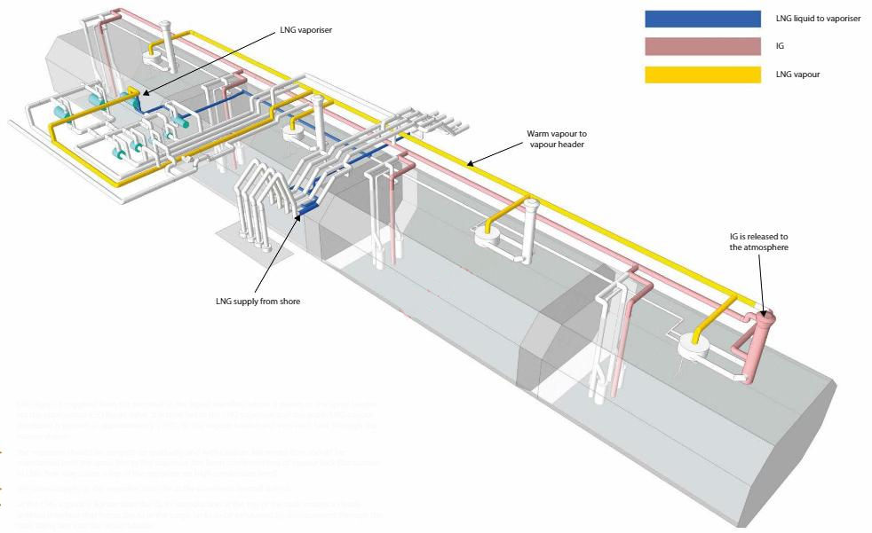
- LNG liquid is supplied from the terminal to the liquid manifold where it passes to the spray header via the appropriate ESD liquid valve. It is then fed to the LNG vaporiser and the warm LNG vapour produced is passed at approximately +20 °C, to the vapour header and into each tank through the vapour domes;
- the vaporiser should be ramped-up gradually and with caution. Minimum flow should be maintained until the spray line to the vaporiser has been confirmed free of vapour lock (fluctuation in LNG flow may cause a trip of the vaporiser on high condensate level);
- the steam supply to the vaporiser must be at the maximum normal output;
- as the LNG vapour is lighter than the IG, its introduction at the top of the tank creates a clearly defined interface that forces the IG in the cargo tanks to be exhausted by displacement through the tank filling line into the liquid header;
- the IG then vents to atmosphere, usually through No. 1 (forward) vent mast;
- because the flow of liquid from the terminal is relatively small for this operation, problems may be experienced due to vapour locking at the loading arms;
- when approximately 5 % CH4 by volume (the actual percentage figure will be specified by the particular Port Authority) is detected at the No. 1 vent mast, the exhausting gas is directed ashore via the HD compressors.
On completion of the gassing-up procedure, the cooldown of the General Overview of LNG Cargo Tanks (Typical Operations)cargo tanks and associated system normally follows immediately.
| Required heat energy at initial purging for a typical 140 000 m3 conventional membrane type LNGC | |||||
|---|---|---|---|---|---|
| Tank | Tank volume (m3) | Required vapour (m3) | Required LNG (kg) | Required LNG (m3) | Heat Energy (MMBTU) |
| No. 1 | 21 943 | 39 497.04 | 32 071,6 | 68,4 | 1 648,5 |
| No. 2 | 40 432 | 72 777,06 | 59 095,0 | 126,0 | 3 037,5 |
| No. 3 | 40 443 | 72 796,9 | 59 111,1 | 126,0 | 3 038,3 |
| No. 4 | 37 831 | 68 095,62 | 55 293,6 | 117,9 | 2 842,1 |
| Total | 140 648 | 253 167,00 | 205 571,0 | 438,0 | 10 566,0 |
| Note: | 1. LNG density: 469,0 kg/m3 | ||||
| 2. LNG heating value: 51 400 MMBTU/ton | |||||
Total vapour required:
Required LNG, LNG total requirement:
- 1,8 · V (100 %) · ρ NG;
- 1,8 · 140 648 · 0,8120;
- 205 571 kg;
- 430,2 m3 of LNG.
Density of ρ NG = 0,8210 kg/m3 AT +20 ° C and 1 060 mbar A.

- The international group of liquefied natural gas importers (GIIGNL). LNG custody transfer handbook / 6th Edition: 2020-2021.
- ©Witherby Publishing Group Ltd. LNG Shipping Knowledge / 3rd Edition: 2008-2020.
- CBS Publishers & Distributors Pvt Ltd. Design of LPG and LNG Jetties with Navigation and Risk Analysis / 4th Edition.
- NATURAL GAS PROCESSING & ITS ENERGY TRANSITION ROLE: LNG, CNG, LPG & NGL Paperback – Large Print, November 14, 2023.
- OCIMF, ICS, SIGTTO & CDI. Ship to Ship Transfer Guide for Petroleum, Chemicals and Liquefied Gases / 1st Edition, 2013.
- The Society of International Gas Tanker and Terminal Operators (SIGTTO). Ship/Shore Interface / 1st Edition, 2018.