This article contains information about cargo tanks placement and also rules survivability of the vessel, that should be followed.
General
Ships subject to this Rules should survive the normal effects of flooding following assumed hull damage caused by some external force. In addition, to safeguard the ship and the environment, the cargo tanks should be protected from penetration in the case of minor damage to the ship resulting, for example, from contact with a jetty or tug, and given a measure of protection from damage in the case of collision or stranding, by locating them at specified minimum distances inboard from the ship’s shell plating.
Both the damage to be assumed and the proximity of the cargo tanks to the ship’s shell should be dependent upon the degree of hazard considered to be presented by the product to be carried.
Guidance: When applying the requirements of this article attention should be given to IMO-document MSC/Circ 406 of 14.06.1985 “Guidelines for the Uniform Application of the Survival Requirements of the IBC/IGC-Codes”.
Ships subject to this Rules is to be designed to one of the following standards.
- A Type 1G Ship is a gas carrier intended to transport products as indicated in “Summary of Minimum Requirements for LNG and LPG tankers”Minimum requirements which require maximum preventative measures to preclude the escape of such cargo.
- A Type 2G Ship is a gas carrier intended to transport products as indicated in “Summary of Minimum Requirements for LNG and LPG tankers”Minimum requirements which require significant preventative measures to preclude the escape of such cargo.
- A Type 2PG Ship is a gas carrier of 150 m in length (Lc) or less intended to transport products as indicated in “Summary of Minimum Requirements for LNG and LPG tankers”Minimum requirements which require significant preventative measures to preclude escape of such cargo, and where the products are carried in independent tanks type C designed (see “Cargo containment system of gas vessel”Type C independent tanks) for a MARVS of at least 7 bar gauge and a cargo containment system design temperature of -55 °C or above. Note that a ship of this description but over 150 m in length is to be considered a Type 2G ship.
- 4A Type 3G Ship is a gas carrier intended to carry products as indicated in “Summary of Minimum Requirements for LNG and LPG tankers”Minimum requirements which require moderate preventative measures to preclude the escape of such cargo.
Thus a Type 1G ship is a gas carrier intended for the transportation of products considered to present the greatest overall hazard and Types 2G/2PG and Type 3G for products of progressively lesser hazards. Accordingly, a Type 1G ship shall survive the most severe standard of damage and its cargo tanks should be located at the maximum prescribed distance inboard from the shell plating. The ship type required for individual products is indicated in column “c” in the table of “Summary of Minimum Requirements for LNG and LPG tankers”Minimum requirements.
If a ship is intended to carry more than one product listed in “Summary of Minimum Requirements for LNG and LPG tankers”Minimum requirements, the standard of damage should correspond to that product having the most stringent ship type requirement. The requirements for the location of individual cargo tanks, however, are those for ship types related to the respective products intended to be carried.
Freeboard and stability
Ships subject to the Rules may be assigned the minimum freeboard permitted by the International Convention on Load Lines, 1966. However, the draught associated with the assignment shall not be greater than the maximum draught otherwise permitted by these Rules. The stability of the ship in all seagoing conditions and during loading and unloading cargo shall be to a standard which is acceptable to the Administration.
When calculating the effect of free surfaces of consumable liquids for loading conditions it shall be assumed that, for each type of liquid, at least one transverse pair or a single center tank has a free surface and the tank or combination of tanks to be taken into account shall be those where the effect of free surface is the greatest. The free surface effect in undamaged compartments shall be calculated by a method acceptable to the Administration.
Solid ballast shall not normally be used in double bottom spaces in the cargo area. Where, however, because of stability considerations, the fitting of solid ballast in such spaces becomes unavoidable, then its disposition should be governed by the need to ensure that the impact loads resulting from a bottom damage are not directly transmitted to the cargo tank structure.
The master of the ship shall be supplied with a Loading and Stability Information booklet. This booklet shall contain details of typical service conditions, loading, unloading and ballasting operations, provisions for evaluating other conditions of loading and a summary of the ship’s survival capabilities. In addition, the booklet shall contain sufficient information to enable the master to load and operate the ship in a safe and seaworthy manner.
Shipside discharges below the freeboard deck
The provision and control of valves fitted to discharges led through the shell from spaces below the freeboard deck or from within the superstructures and deckhouses on the freeboard deck fitted with weathertight doors shall comply with the requirements of Regulation 22 of the International Convention on Load Lines 1966, except that the choice of valves shall be limited to:
- one automatic non-return valve with a positive means of closing from above the freeboard deck, or
- where the vertical distance from the summer load waterline to the inboard end of the discharge pipe exceeds 0,01 Lc, two automatic non-return valves without positive means of closing, provided that the inboard valve is always accessible for examination under service conditions, i.e. the valve is to be situated above the tropical or subdivision load line.
For the purpose of this article “summer load waterline” and “freeboard deck”, have the meanings as defined in the International Convention on Load Lines, 1966.
The automatic non-return valves referred above shall be fully effective in preventing admission of water into the ship, taking into account the sinkage, trim and heel in survival requirements (see below) and shall comply with Recognized Standards. For automatic non-return valves see Rules for Machinery Installations, Volume III, Section 11.
Condition of loading
Damage survival capability shall be investigated on the basis of loading information submitted to the Administration or all anticipated conditions of loading and variations in draught and trim. The survival requirements need not be applied to the ship when in the ballast condition, provided that any cargo retained on board is solely used for cooling, circulation or fuelling purposes.
Note: Small independent purge tanks on deck need not be taken into account in the stability calculations for the ballast condition.
Damage assumptions
The assumed maximum extent of damage shall be in accordance with Table 1.
| Table 1. Damage assumptions | ||
|---|---|---|
| Side damage | ||
| Longitudinal extent | 1/3 or 14,5 m whichever is less | |
| Transverse extent | measured inboard from the ship’s side at rightangle to the centre line at the level of the summer load line | B/5 or 11,5 m whichever is less |
| Vertical extent | from the moulded line of the bottom shelplating at centre line | upward without limit |
| Bottom damage | ||
| For 0,3 from the forward perpendicular of the ship | Any other part of the ship | |
| Longitudinal extent | 1/3 or 14,5 m whichever is less | 1/3 or 5 m whichever is less |
| Transverse extent | B/6 or 10 m whichever is less | B/6 or 5 m whichever is less |
| Vertical extent | B/15 or 2 m whichever is less, measured from the moulded line of the bottom shell plating at the centre line (see below). | B/15 or 2 m whichever is less, measured from the moulded line of the bottom shell plating at the centre line (see below). |
Other damage:
- If any damage of a lesser extent than the maximum specified above would result in a more severe condition, such damage should be assumed.
- Local side damage anywhere in the cargo area extending inboard 760 mm measured normal to the hull shell should be considered and transverse bulkheads should be assumed damaged when also required by the applicable .
Location of cargo tanks
Cargo tanks are to be located at the following:
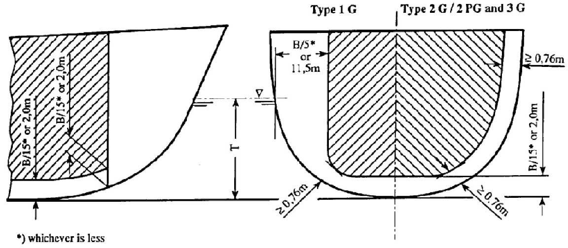
- Type 1G ships: from the side shell plating not less than the transverse extent of damage specified above and from the moulded line of the bottom shell plating at center line not less than the vertical extent of damage specified in above, and nowhere less than 760 mm from the shell plating.
- Types 2G/2PG and 3G ships: from the moulded line of the bottom shell plating at center line not less than the vertical extent of damage specified above and nowhere less than 760 mm from the shell plating.
For the purpose of tank location, the vertical extent of damage is to be measured to the inner bottom when membrane or semi-membrane tanks are used, otherwise to the bottom of the cargo tanks. The transverse extent of damage is to be measured to the longitudinal bulkhead when membrane or semi-membrane tanks are used, otherwise to the side of the cargo tanks (see Pic. 1). For internal insulation tanks the extent of damage is to be measured to the supporting tank plating.
Except for Type 1G ships suction wells installed in cargo tanks may protrude into the vertical extent of bottom damage specified above provided that such wells are as small as practicable and that the protrusion below the inner bottom plating does not exceed 25 % of the depth of double bottom or 350 mm whichever is less. Where there is no double bottom, the protrusion below the upper limit of bottom damage is not to exceed 350 mm. Suction wells installed in accordance with this paragraph may be ignored in determining the compartments affected by damage.
Flooding assumptions
The survival requirements shall be confirmed by:
- calculations which take into consideration the design characteristics of the ship;
- the arrangements, configuration and contents of the damaged compartments;
- the distribution, relative densities and the free surface effects of liquids;
- and the draught and trim for all conditions of loading.
The permeabilities of spaces assumed to be damaged are to be taken as given in Table 2.
| Table 2. Permeability of spaces | |
|---|---|
| Space | Permeability |
| appropriated to stores | 0,60 |
| occupied by accommodation | 0,95 |
| occupied by machinery | 0,85 |
| voids | 0,95 |
| intended for consumable liquids | 0 to 0,95 The permeability of partially filled compartments shall be consistent with the amount of liquid carried in the compartment.x |
| intended for other liquids | 0 to 0,05 The permeability of partially filled compartments shall be consistent with the amount of liquid carried in the compartment.x |
Wherever damage penetrates a tank containing liquids, it shall be assumed that the contents are completely lost from that compartment and replaced by salt water up to the level of the final plane of equilibrium.
Where the damage between transverse watertight bulkheads is envisaged as specified in “Standard of damage” and “Damage assumptions” in order to be considered effective. Where transverse bulkheads are spaced at a lesser distance, one or more of these bulkheads within such extent of damage should be assumed as non-existent for the purpose of determining flooded compartments. Further, any portion of a transverse bulkhead bounding side compartments or double bottom compartments shall be assumed damaged if the watertight bulkhead boundaries are within the extent of vertical or horizontal penetration required by damage assumptions.
Also, any transverse bulkhead shall be assumed damaged if it contains a step or recess of more than 3 m in length located within the extent of penetration of assumed damage. The step formed by the after peak bulkhead and after peak tank top shall not be regarded as a step for the purpose of this paragraph.
The ship shall be so designed as to keep asymmetrical flooding to the minimum consistent with efficient arrangements.
Equalization arrangements requiring mechanical aids such as valves or cross-levelling pipes, if fitted, shall not be considered for the purpose of reducing an angle of heel or attaining the minimum range of residual stability to meet the requirements of survival and sufficient residual stability shall be maintained during all stages where equalization is used. Spaces which are linked by ducts of large cross-sectional area may be considered to be common.
If pipes, ducts, trunks or tunnels are situated within the assumed extent of damage penetration, as defined in “Damage asumptions” arrangements shall be such that progressive flooding cannot thereby extend to compartments other than those assumed to be flooded for each case of damage.
The buoyancy of any superstructure directly above the side damage shall be disregarded. The unflooded parts of superstructures beyond the extent of damage, however, may be taken into consideration provided that:
- they are separated from the damaged space by watertight divisions and the requirements of survival in respect of these intact spaces are complied with;
- and openings in such divisions are capable of being closed by remotely operated sliding watertight doors, and unprotected openings are not immersed within the minimum range of residual stability; however, the immersion of any other openings capable of being closed weathertight may be permitted.
Standard of damage
Ships shall be capable of surviving the damage indicated in “Damage assumptions” with the flooding assumptions to the extent determined by the ship’s type according to the following standards:.
- A Type 1G ship shall be assumed to sustain damage anywhere in its length;
- A Type 2G ship of more than 150 m in length shall be assumed to sustain damage anywhere in its length;
- A Type 2G ship of 150 m in length or less shall be assumed to sustain damage anywhere in its length, except involving either of the bulkheads bounding a machinery space located aft;
- A Type 2PG ship shall be assumed to sustain damage anywhere in its length, except involving transverse bulkheads spaced further apart than the longitudinal extent of damage as specified in “Damage assumptions”;
- A Type 3G ship of 125 m in length or more shall be assumed to sustain damage anywhere in its length, except involving transverse bulkheads spaced further apart than the longitudinal extent of damage specified in “Damage assumptions”;
- A Type 3G ship of less than 125 m in length shall be assumed to sustain damage anywhere in its length, except involving transverse bulkheads spaced further apart than the longitudinal extent of damage specified in “Damage assumptions” and except damage involving the machinery space when located aft. However, the ability to survive the flooding of the machinery space shall be considered by the Administration.
In the case of small Type 2G/2PG and Type 3G ships which do not comply in all respects with the appropriate requirements listed above, special dispensations may only be considered by the Administration provided that alternative measures can be taken which maintain the same degree of safety. The nature of the alternative measures shall be approved and clearly stated and be available to the Port Administration. Any such dispensation shall be duly noted on the International Certificate of Fitness for the Carriage of Liquefied Gases in Bulk.
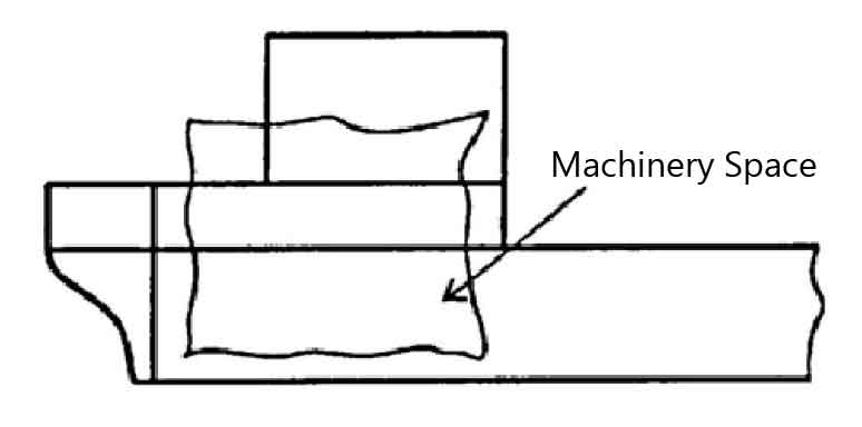
The longitudinal extent of damage to superstructure in the instance of side damage to a machinery space aft shall be the same as the longitudinal extent of the side damage to the machinery space (see Pic. 2).
Survival requirement
Ships subject to the Rules shall be capable of surviving the assumed damage specified in “Damage assumptions” to the standard provided in “Standart of damage” in a condition of stable equilibrium and shall satisfy the following criteria:
In any stage of flooding:
- The waterline taking into account sinkage, heel and trim shall be below the lower edge of any opening through which progressive or downflooding may take place. Such openings shall include air pipes and openings which are closed by means of weathertight doors or hatch covers, and may exclude those openings closed by means of watertight manhole covers and watertight flush scuttles, small watertight cargo tank hatch covers which maintain the high integrity of the deck, remotely operated watertight sliding doors, and side scuttles of the non-opening type;
- the maximum angle of heel due to unsymmetrical flooding shall not exceed 30°;
- and the residual stability during intermediate stages of flooding shall be to the satisfaction of the Administration. However, it shall never be significantly less than that required below.
At final equilibrium after flooding:
- the righting lever curve shall have a minimum range of 20° beyond the position of equilibrium in association with a maximum residual righting lever of at least 0,1 m within the 20° range; the area under the curve within this range shall not be less than 0,0175 meter radians. Unprotected openings shall not be immersed within this range unless the space concerned is assumed to be flooded. Within this range, the immersion of any of the openings listed above and of other openings capable of being closed weathertight may be permitted;
- and the emergency source of power shall be capable of operating.
The 20°range may be measured from any angle commencing between the position of equilibrium and the angle of 30° see Pic. 3.
