The custody transfer system for Liquefied Natural Gas (LNG) is a critical component of the LNG supply chain, designed to ensure accurate and reliable measurement during the transfer of ownership. The general arrangement of a custody transfer system is carefully planned to minimize measurement uncertainty and maintain the integrity of the LNG being transferred. This arrangement usually involves a series of sophisticated instruments, including flow meters, densitometers and temperature and pressure sensors, strategically placed to provide precise data for accurate calculations of the LNG mass or volume.
The physical layout of the custody transfer system is a vital aspect of its overall effectiveness. Components must be easily accessible for maintenance and calibration, and the overall design should minimize potential sources of error, such as vapor formation or stratification. Redundancy is often integrated into the custody transfer system arrangement to ensure continuous operation and data validation, enhancing reliability. Strict adherence to industry standards and regulations is paramount in the design and operation of any custody transfer system to guarantee fair and transparent fiscal transfer.
Custody Transfer System
Introduction
Custody transfer refers to the process that takes place when one company purchases a quantity of crude oil, chemicals, natural gas, or any similar product from another company, and that product is transferred by loading it into, or from, a ship, rail car, storage tank, pipeline, or truck.
If you transfer a large amount of material, accuracy becomes important, because a small error can mean thousands of dollars in lost revenue to one company and extra profit to the other. In Europe, where custody transfer is governed by very strict government regulations, level transmitters are an accepted method.
In the U.S. however, acceptable methods of measuring custody transfer are determined by mutual agreement between buyer and seller, and usually invoke American Petroleum Institute (API) standards.
Many accountants and contract writers (but few engineers) disagree on whether automatic tank gauging (ATG) systems are accurate enough for custody transfer, and stick to manual gauging practices.
LNG is bought and sold on its calorific content, normally expressed in Btu’s rather than on a volume or weight basis. However, at the present time there are no practical instruments available to determine the net calorific content transferred during loading and discharge so that for the moment this value is determined partly by measurement and partly by analysis of cargo calculation by means of the following formula:
where :
Q – Total energy transferred.
V – Cargo volume loaded or discharged at an average temperature TL (m3).
d – Density of cargo at temperature TL (kg/m3).
HL – Gross heating value of the cargo (Btu/kg).
Ts – Standard temperature (°K).
Tv – Average temperature of gas in the cargo tanks (°K).
TL – Average temperature of liquid in cargo tanks (°K).
Pv – The absolute pressure of the gas in the cargo tanks, that is, gauge pressure of gas + barometric pressure (kPa).
Hv – The gross heating value of gas vapor at 15,6 °C and 101,3 kPa (Btu/m3). This value is assumed to be a constant 36 000 Btu/m3 based on pure methane.
In establishing the value of the cargo transferred to and from the ship, the vessel’s responsibility is limited to measurement/calculation of the following values:
- V,
- Tv,
- Pv.
These measurements/calculations are made by ship and shore representatives and are normally verified by an independent surveyor. The values HL and d are determined ashore at the loading and discharge ports and the calculations are completed by the buyers and sellers.
The quantity of cargo delivery is expressed in MMBtu or tons.
History of Custody Transfer Systems
The original technology, developed by Robert Blanchard and Arthur Sherburne of Trans-Sonics, Inc., provided precise capacitance liquid-level gauging, a capability required by NASA for real-time rocket fuel gauging on the Saturn V and lunar landing modules. The accurate readout of remaining fuel was critical to the performance of the rockets, as was shown in 1969 when Apollo 11 achieved the first manned lunar landing.
Known as the Liquefied Natural Gas (LNG) Custody Transfer System, this Apollo-born technology is used by more than three-quarters of the world’s Comprehensive Framework: Primary & Secondary Barrier Testing Protocols on LNG TankersLNG tankers and is manufactured by the Foxboro Company of Massachusetts (now Invensys Process Systems/Foxboro).
Although recent technologies are now starting to replace this type of LNG system, it is still used on 115 tankers worldwide with a trade valued at $20 billion a year.
Custudy Transfer Measurement
The Custody Transfer System provides the high accuracy measurements and data logging of levels, temperatures and pressures required for the calculation of total LNG cargo loaded or discharged.
All custody transfer measurements can be displayed on a VDU in the CACC and in addition liquid level measurements of each tank can be individually displayed on the remote 5-digit LED-type digital indicators on the cargo area console.
The system automatically scans and prints the values of the selected measurement. In addition, the data is converted to volumetric and mass measure, corrected for the ship’s list and trim based on manual and automatic inputs from a software configured to handle various functions.
The software configuration includes manually input density data representative of the total cargo from a cargo composition library stored in memory:
- 2 analogue inputs for list and trim;
- volume expression in m3;
- mass expression in tons.
Custody transfer measurement takes place before and after loading and discharging. During gauging, all cargo systems on the ship should be closed and the shore connections isolated or disconnected. No ballast operations should take place during measurement and the vessel should, if possible, be on even keel and upright. However, the operation can be conducted with a slight trim if the corrections included in the tank calibration tables are applied.
Custody transfer documents are produced detailing the volumes of cargo and vapor transferred during both loading and discharge operations.
Custody Transfer System – Level Measurement
a) FOXBORO CAPACITIVE LEVEL GAUGES
In 1969 Foxboro first introduced capacitive level gauges for LNG applications.
In the following 30+ years, capacitive sensors have been the heart of custody transfer systems used for liquified natural gas (LNG) production and transport aboard ships.
Until recently, Foxboro Transonics and its affiliate companies were the only companies that provided LNGC Custody Transfer Systems (CTS).
The level measurement system consists of a long coaxial sensor installed in the tank and extends over the full depth in, which the level is to be measured.
The liquid level is determined by measuring the electrical capacitance of the sensor segment intersecting the liquid level. The capacitance of this segment is compared with the capacitance of a reference segment located below the liquid surface. The ratio of these two measurements results in the accurate determination of liquid level that is independent of liquid properties such as dielectric constant, temperature and density.
This ratiometric method of cargo level measurement includes a calibration assurance feature incorporated to maintain the accuracy of the level measuring sub-system; this system is called the ON-LINE Validation System.
The level measurement accomplished provides an accuracy of ± 7,5 mm over the entire gauging height. The display resolution is 1 mm at the system workstation and printer.
b) SAAB MARINE RADAR TANK GAUGING SYSTEM
In 1996, SAAB Marine Electronics revolutionized CTS by introducing its “radar” tank gauging system for General information and Rules for Ships carrying LNG and LPGLNG ships.
In comparison to the Foxboro Capacitive Sensor system, the SAAB system is completely outside of the tank and accessible at all times – even with cargo in the tank(s).
Typically, level gauges used for legal custody transfer in Europe have an intrinsic accuracy within 1 mm and an installed accuracy within 2-3 mm.
Figure 1 shows the principle of functioning of a radar level gauge.
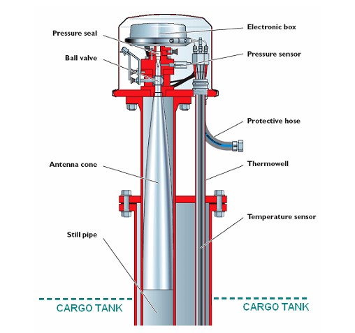
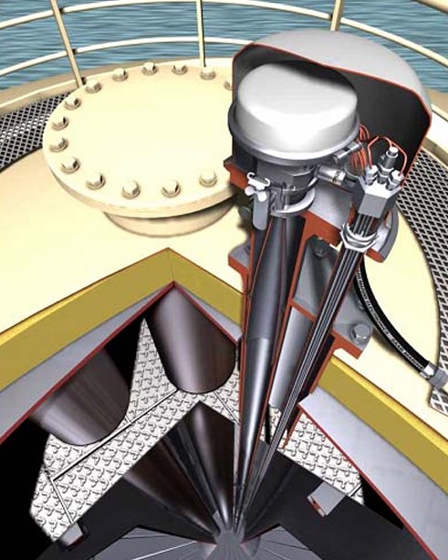
The still pipe guides the radar waves. The electronic box generates and transmits radar waves into the antenna cone. It provides a smooth transition for the waves into the still pipe. Because the still pipe guides the radar waves, very little signal energy is lost. This results in a strong echo from the liquid surface. Figure 2 is an artistic view of the actual arrangement of a SAAB level gauge.
The Saab Tank Radar gauge is installed on top of a still pipe. The temperature sensors are installed in a thermo-well. This means that the electronic box and the temperature sensors can be easily replaced, with the tank in operation.
The main components for Saab Tank Radar are:
- the tank gauges that measure ullage, vapor pressure as well as liquid and vapor temperature;
- the level unit that contains much of the calculation power for the signal processing and the circuits for ensuring the intrinsic safety. The tank gauges are connected to the level unit. The signal processors and memory circuits are doubled for internal redundancy in the level unit;
- the work stations that calculate the cargo volume from tank parameters and measured values. They also supervise and warn of any alarms that may occur. A work station consists of a PC that is type approved for operating in the marine environment. A printer is included for printing custody transfer reports and various logs;
- the redundancy box that automatically switches master Work Station, if the active master fails.
c) AUTRONICA RADAR TANK GAUGING SYSTEMS
Kongsberg Simrad acquired Autronica and in 1984 introduced the first radar level gauging system certified for LPG/LNG.
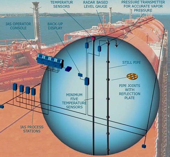
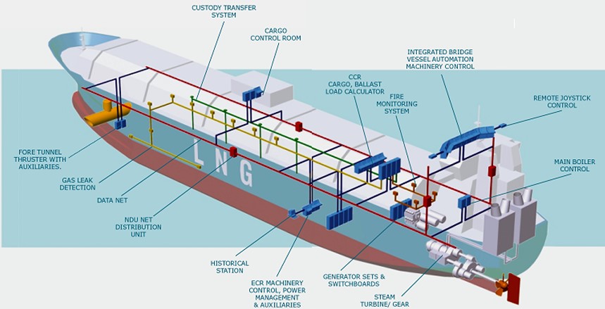
Today’s radar head is based on the 2nd generation technology and includes features to make the system a complete Custody Transfer System (CTS). It can be installed as a stand-alone system with a serial line interface to a general IAS Additional functionality is added if it is supplied as a part of Kongsberg Simrad’s IAS. See Figures 3 and 4.
d) FOXBORO LASER TANK GAUGING SYSTEM
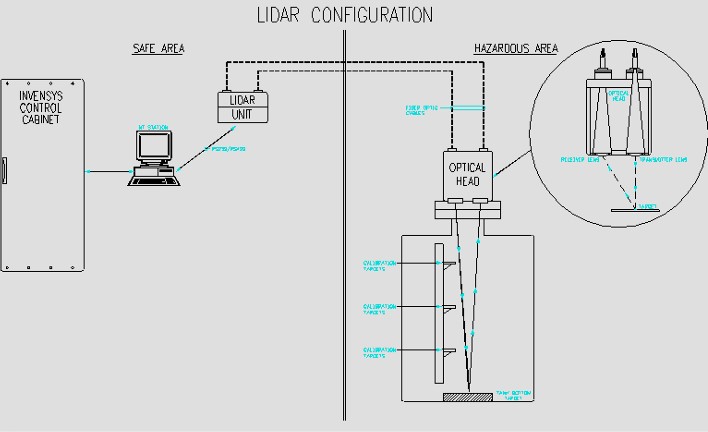
Not to be outdone by competition from Radar Tank Gauging systems, Foxboro/Invensys Corp has announced a new format for CTS called Custody Transfer System Reference 5.
It uses non-intrusive laser technology to provide precise measurements of level, temperature, and pressure. The system is installed quickly and easily by simply bolting it to the side of an LNG tank. The cost of ownership is equal to or less than RADAR – and the accuracy is far superior.
Figure 5 shows the scheme of this system and Figure 6 a couple of photographs.

e) SUMMARY
There are 3 major CTS suppliers:
- Foxboro,
- Saab,
- Kongsberg Simrad.
The components for all systems (i. e., cpu, redundancy module, hot swap feature, etc.) basically the same except for means of measuring liquid level in tank.
There are 3 basic types of CTS measurement:
- Capacitance,
- Radar,
- Laser.
Capacitance type has a long and proven history of reliability and accuracy. Repairs to capacitance type may require taking a tank out of service. Radar type is newer; laser is newest, both have proven themselves to be accurate and reliable. Repairs to radar and laser types do not require taking tank out of service.
f) TRADITIONAL LEVEL GAUGING SYSTEMS
In the event of total failure of the CTS system, level sensing devices, a marine liquid level gauge (Whessoe type) may be used for level measurement -providing that approval is given by the shore representatives.
The accuracy of the float gauge is the same as the capacitance gauge. The float of the gauge must be maintained blocked at the top position except when during the actual measurement.
The total gross number of cubic meters of cargo in the tanks before and after loading or discharging is calculated using the average level reading determined. This volume is corrected for:
- heel,
- trim,
- volume,
- vapor pressure,
- cargo and vapor temperatures.
The difference in these volumes at the start and end of the operation will be taken as the apparent volume (m3) of cargo delivered. The Whessoe float level measurement system is of conventional tanker type, but uses an Invar tape to compensate for temperature variations.
A gauge head, containing a mechanical indicator, an Invar tape tensioned by a negator spring and a 12 diameter PV float attached to the lower end of the tape, is fitted to each liquid dome.
Two guide wires for the float are attached at the lower ends to an anchor bar 130 mm above the tank bottom, which is secured to the trellis structure base plate.
The sinkage of the float in LNG is 15 mm and the minimum level, which can be read from the gauge is 145 mm.
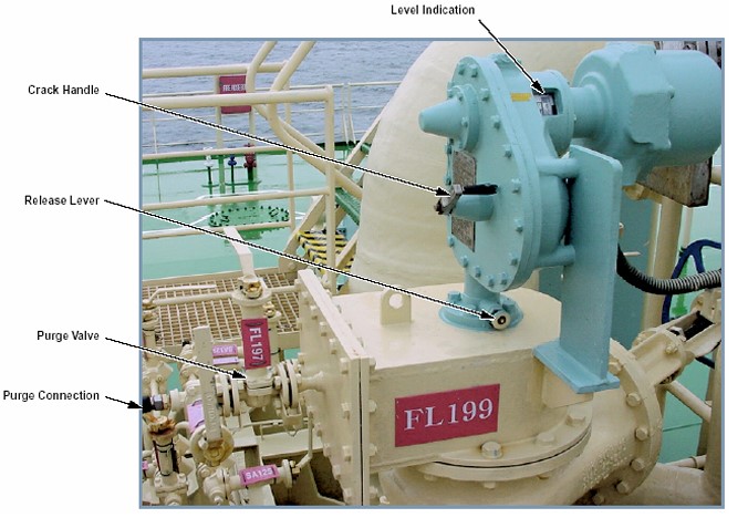
Figures 7 and 8 show a level gauge Whessoe type.

Trim-List Indicator
The ship is provided with a fixed trim-list indicator system for Custody Transfer Measurement System (CTMS) on Liquefied Gas Carriersthe custody transfer system (see Figure 9).
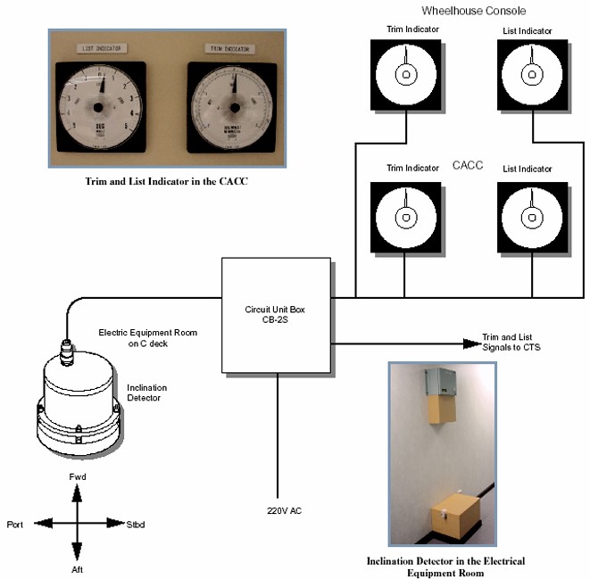
The detector is installed in the electric equipment room with indicators at the CACC cargo console and a repeater on the bridge console. The measurement principle is that a suspended mass within the inclination detector moves from a center position when the ship trim or list varies.
The movement is detected by linear variable differential transformer coils. A local circuit unit box converts this into a 4 to 20 m3 signal for each axis and these are fed to the CTS interface.
The detector is deck-mounted and contained inside a wooden box, the cover of, which is closed and has an official seal. The power on control box is mounted directly above.
As the response is set to 0,5 s, the system cannot give reliable readings under way.
Temperature Measurement
Temperature measurements are not only necessary for the purpose of calculating the actual equivalent Btu of the cargo for the purpose of the custody transfer system, but also for other important safety aspects. As in today’s ship the various control systems are fully integrated, the temperature measurements are covered in this sub-chapter independently on the purpose they are taken for.
Temperature measurement is accomplished by means of platinum resistance transducers (500 ohms) providing an accuracy of ± 0,2 °C from -165 °C to 145 °C, ± 0,3 °C up to – 120 °C and ± 1 – 5 °C up to + 80 °C.
Data is displayed at the system workstation and printer with a resolution of 0,01 °C. There are five active and five spare temperature sensors in each tank and each reading is recorded.
The determination of whether the temperature point is in vapor or liquid will be made from the liquid level indication. It is safe to assume that any point that indicates a temperature of more than 3° above the LNG temperature must be in the vapor space.
Although the temperature variation over the depth of liquid should be no more than a fraction of a degree, the variation of vapor temperature, particularly at the end of discharge, will be more pronounced.
The temperature of the cargo is about –160 °C at atmospheric pressure depending of the exact composition of the LNG. The cargo temperature will stay at –160 °C as long there is some LNG in the tank and the pressure is the atmospheric pressure but a lot of boil-off (evaporation of the liquid cargo) can be generated if the insulating system has a poor efficiency. The control of the temperature becomes the control of the pressure in the tank.
Temperature control is also essential to be sure that the temperature of the ship structures surrounding the cargo tanks is kept within acceptable limits.
Each cargo tank should be provided with at least two devices for indicating cargo temperature, one placed at the bottom of the cargo tank and the second near the top of the tank, below the highest allowable liquid level. That is the minimum required by the IGC code. Actual ship are provided with more temperature indicators: usually 5 or more temperature sensors are fitted on the pump tower at different levels: ie bottom, 10 %, 30 %, 60 %, 90 %, 95 % and above.
Also some temperature sensors are placed right below the secondary barrier or just above the secondary barrier to confirm the efficiency of the insulating system.
Some temperature sensors are placed on the inner hull to monitor the temperature (two per cargo tank in the trunk spaces and three per cargo tank in the duct keel).
Monitoring equipment is provided in the CACC for insulation space and inner hull temperatures to give warning in case of failure of insulation or leakage of the secondary insulation space barrier.
Each sensor is of PT 100 resistance type. The sensors are installed in Interbarrier Space Protection: Pressurization, Inertization and Scaffolding Techniquesthe interbarrier space and alongside the inner hull associated with each cargo tank (see figure 10).
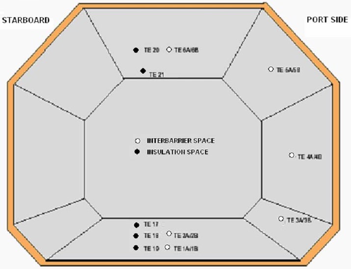
The temperature range of each sensor is: -170 °C to +50 °C.
The interbarrier space thermocouples (sensors) are installed at 6 points around the space, all 6 of them in pairs. During normal conditions, one thermocouple is in service while the other is on standby. If the first sensor fails, the second will automatically come into service.
For the inner hull temperature measurements there are 5 sensors in each tank, 3 are located along the bottom of the tank in the duct keel, while 2 sensors are located in the trunk deck.
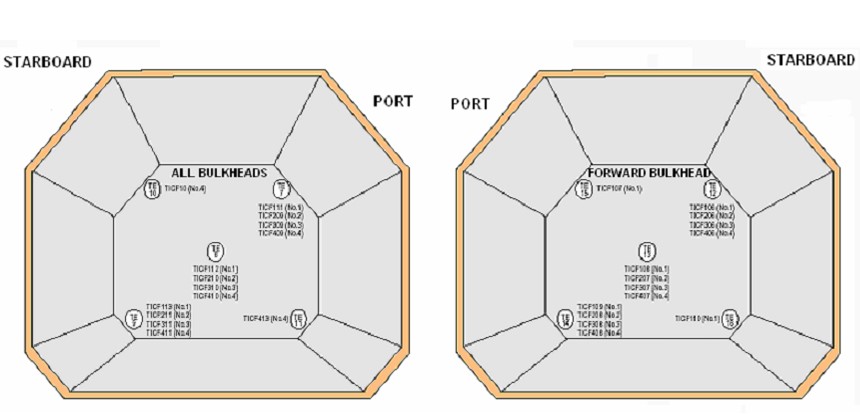
In the cofferdam spaces there are 3 temperature sensors on each of the forward and aft bulkheads, except the forward bulkhead of No.1 cofferdam, which has 5 sensors and the aft bulkhead of No.5 cofferdam, which also has 5 sensors. (See Figure 11).
The temperature measurements are indicated for each thermocouple in service in the CACC via the IAS.
Recording of these temperatures is also available via the IAS. The thermocouples for the insulation space sensors alarm point are set at -120 °C. The thermocouples for the inner hull sensors alarm point are set at 0 °C.
Pressure Measurement and Control
Pressure measurements are not only necessary for the purpose of calculating the actual equivalent Btu of the cargo for the purpose of the custody transfer system, but also for other important safety aspects. As in today’s ship the various control systems are fully integrated, the pressure measurements are covered in this sub-chapter independently on the purpose they are taken for.
Absolute pressure measurements in each of the cargo tanks are determined by intelligent pressure transmitters. The accuracy of the measurement is ± 0,1 % of span to a resolution of 0,1 kPa at system workstation and printer.
Range of measurement is 80,0 to 140,0 kPa. Ambient temperature effect on the transmitter is ± 0,2 % per 55 °C change between limits of –30 °C and +60 °C.
For the membrane LNG carrier, the tank pressure is to be below 25 kPa. In order to keep the pressure below 25 kPa, there are two possibilities:
- A system, which regulates the pressure in the cargo tanks by the use of mechanical refrigeration: that is the re-liquefaction of the boil-off, which is commonly used on the LPG, but so far not on LNG carrier. There are some projects but still at the state of project (except one experimental ship by Mitsui).
- A system where the boil-off is utilized as fuel for shipboard use or waste heat system. This system may be used at all times including while in port and while maneuvering, provided that a means of disposing the excess energy is provided such as a steam dump system.
As long as the pressure of the cargo tank is equal to the atmospheric pressure, the temperature of the liquid cargo will be around –160 °C; then it is imperative to keep the pressure at the atmospheric pressure or below the design pressure of the cargo tank: 25 kPa.
For this effect the boil off is used as fuel for shipboard with a waste heat system (steam dump). The methane is the only cargo whose the boil-off gas may be utilized in machinery spaces of category A and in such spaces may be utilized only in boilers, inert gas generators, combustion engines and gas turbines.
The vapor space of each cargo tank is provided with a pressure gauge, which should incorporate an indicator in the CACC. In addition, a high pressure alarm and a low pressure alarm, is provided on the navigation bridge. Maximum and minimum allowable pressure are marked on the indicators.
Each cargo pump discharge line and each liquid and vapor cargo manifold is provided with at least one pressure gauge. Local reading manifold pressure gauges are provided to indicate the pressure between stop valve and hose connection to the shore.
Hold space and interbarrier spaces without open communication to the atmosphere are to be provided with pressure gauges.
Custody Transfer System General Arrangement
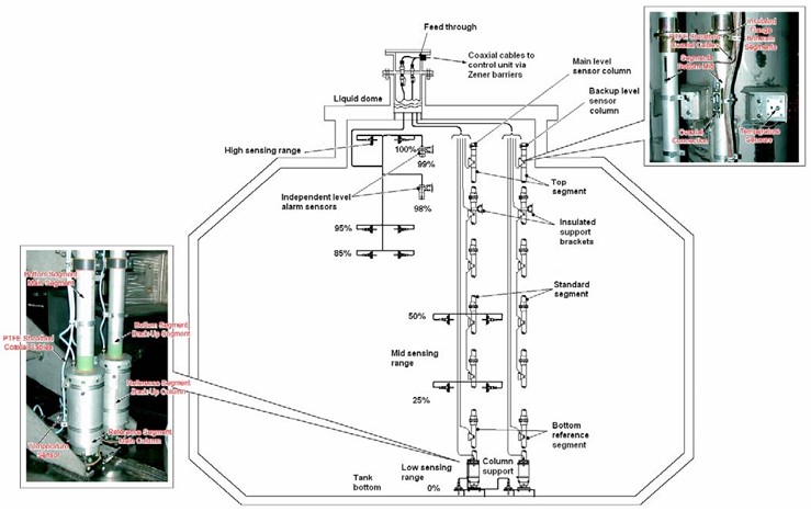
Figure 12 shows the arrangement of various sensors and equipment relative to the custody transfer system.

- The Society of International Gas Tanker and Terminal Operators (SIGTTO). Liquefied Gas Handling Principles on Ships and in Terminals (LGHP4) / 4th Edition: 2021.
- The international group of liquefied natural gas importers (GIIGNL). LNG custody transfer handbook / 6th Edition: 2020-2021.
- American Gas Association, Gas Supply Review, 5 (February 1977).
- ©Witherby Publishing Group Ltd. LNG Shipping Knowledge / 3rd Edition: 2008-2020.
- CBS Publishers & Distributors Pvt Ltd. Design of LPG and LNG Jetties with Navigation and Risk Analysis / 4th Edition.
- NATURAL GAS PROCESSING & ITS ENERGY TRANSITION ROLE: LNG, CNG, LPG & NGL Paperback – Large Print, November 14, 2023.
- American Gas Association, Gas Supply Review, 5 (February 1977).
- The Society of International Gas Tanker and Terminal Operators (SIGTTO). Ship/Shore Interface / 1st Edition, 2018.
- Department of Transportation, US Coast Guard, Liquefied Natural Gas, Views and Practices Policy and Safety, p. IV-3.
- Department of Transportation, US Coast Guard, Liquefied Natural Gas, Views and Practices Policy and Safety, p. IV-4.
- Federal Power commission, Trunkline LNG Company et al., Opinion No. 796-A, Docket No s. CP74-138-140 (Washington, D. C.: Federal Power Commission, June 30, 1977).
- Federal Power Commission, Final Environmental Impact Statement Calcasieu LNG Project Trunkline LNG Company Docket No. CP74-138 et al., (Washington, D. C.: Federal Power Commission, September 1976).
- Federal Power Commission, «FPC Judge Approves Importation of Indonesia LNG».
- OCIMF, ICS, SIGTTO & CDI. Ship to Ship Transfer Guide for Petroleum, Chemicals and Liquefied Gases / 1st Edition, 2013.
- Federal Power Commission, «Table of LNG imports and exports for 1976», News Release, June 3, 1977, and Federal Energy Administration, Monthly Energy Review, March 1977.
- Office of Technology Assessment LNG panel meeting, Washington, D. C., June 23, 1977.
- Socio-Economic Systems, Inc., Environmental Impact Report for the Proposed Oxnard LNG Facilities, Safety, Appendix B (Los Angeles, Ca.: Socio-Economic Systems, 1976).
- «LNG Scorecard», Pipeline and Gas Journal 203 (June 1976): 20.
- Dean Hale, «Cold Winter Spurs LNG Activity»: 30.