Dive into the world of Custody Transfer Measurement Systems (CTMS) tailored for LNG carriers. Explore how these precision instruments ensure accurate measurement during the transfer of liquefied natural gas, enhancing efficiency and reliability in maritime operations.
Reference: SIGTTO “LNG Shipping Suggested Competency Standards”, Sections:
1 Have an awareness of the purpose and operating principles.
2 Know and understand their purpose, principles, types, operating requirements, procedures and application:
- pre-loading;
- post loading.
3 Know and understand principles:
- maintenance;
- calibration.
General
LNG is transported at “fully refrigerated” conditions at a temperature of minus 161,5 °C (-161,5 °C) (at Boiling Point – Definition and Pronunciationboiling point). At these low temperatures, measuring, sampling, quantification and testing creates a number of practical problems.
Cargo calculations are made by a system containing high accuracy level, temperature and pressure measuring equipment the meets the requirements for custody transfer. This is known as the custody transfer measurement system (CTMS), or custody transfer system (CTS).
LNG is bought and sold according to its total heat content. To determine this value, the total mass of cargo (volume · density) is measured and multiplied by the calorific value (CV) of the mixture.
What is BTU?
BTU – British Thermal Unit. This is the quantity of heat required to raise the temperature of 1 lb of water through 1 °F.
The CTMS allows cargoes to be bought and sold by heat value in BTU (British Thermal Units) or in Kilo/cal. To determine the amount of energy transferred, an accurate determination of volume, density and composition must be made.
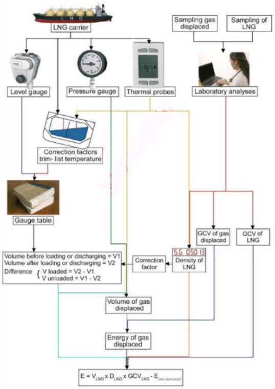
Calculation is through a combination of measurement and analysis of the cargo calculation using the formula:
where:
- V – cargo volume (loaded or disch) at an average temperature of TL (m3);
- d – density of cargo at temp. TL (kg/m3);
- HL – gross heating value of the cargo (BTU/kg);
- Ts – standard temperature (°K);
- Tv – average temperature of gas in the cargo tanks (°K);
- TL – average temperature of liquid in cargo tanks (°K);
- Pv – absolute pressure of the gas in the cargo tanks, i. e. gauge pressure of gas – barometric pressure (kPa);
- Hv – gross heating value of gas vapour at +15,6 °C and 101,3 kPa (BTU/m3). This value is assumed to be a constant 36 000 BTU/m3 and is based on pure methane (MLNG uses BTU/scf).
When determining the value of the cargo transferred to/from the ship, the ship’s concern is the measurements and calculations of the values of V, Tv and Pv.
These measurements/calculations are made by ship and shore representatives and are generally verified by an independent surveyor. The values HL and dare determined ashore, at the loading and discharge ports, and the calculations are completed by the buyers and sellers. The quantity of cargo delivery is expressed in cubic metres (m3).
The CTMS equipment gathers the following measurements from each cargo tank:
- liquid level;
- trim and list indicator;
- density;
- pressure;
- temperature.
Density
There are two methods of determining density:
- the first measures the average value in the LNG carrier’s tank using densimeters. This can be either based on di-electric constant derived directly from the capacitance measurement or using an in tank densimeter based on Archimedes displacement principle;
- the second method enables the density to be calculated on the basis of an average composition of LNG.
In-situ measurements with the help of a densimeter take into account the LNG’s state of equilibrium and composition, which means that they no longer depend on product sampling and analysis. While this would be the best method for measuring LNG density, technological progress has not yet reached the stage where it is possible for a reliable apparatus to be available on board an LNGC under normal operating conditions.
This is why the second method, which enables the density to be calculated from the LNG average composition, is the one that has been selected by the industry and will be used in this section.
where:
- E – the total net energy transferred from the loading facilities to the LNG carrier from the LNG carrier to the unloading facilities or from one LNG carrier to another;
- VLNG – the volume of LNG loaded or unloaded in m3;
- DLNG – the density of LNG loaded or unloaded in kg/m3;
- GCVLNG – the gross calorific value of the LNG loaded or unloaded in MMBTU/kg;
- EGAS DISPLACED – the neat energy of the displaced gas in MMBTU, which is either:
- sent back by the LNG carrier to shore or to another LNG carrier or,
- gas received by the LNG carrier in its cargo tanks when unloading in replacement of the volume of discharged LNG.
Level
A minimum of 2 independent gauges are installed in each tank, although a single measuring system may be provided so that it can be maintained externally.
It is common for the radar gauges to be considered as the primary system and for a float level system to be used as the secondary system.
The radar type is accurate to ± 5 mm. The capacitance type is accurate to ± 7 mm.
The LNG industry considers the accuracy of level gauges to be satisfactory at ± 7,5 mm. On a fully loaded LNG carrier this represents approximately 11 tons.
Temperature
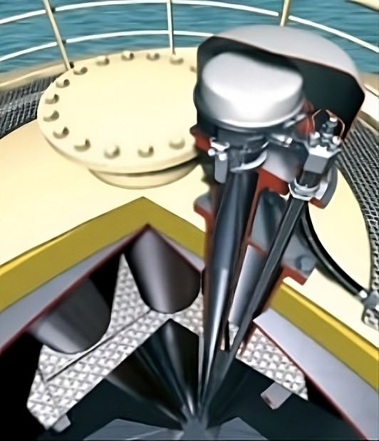
Most LNG carriers are equipped with a number of temperature gauging devices, which are built into the cargo tanks in thermo wells or installed as single probes on the inner or outer shell of the tank. The probes are evenly mounted at regular interval heights. Usually, 5 or 6 probes are designed to give a single read-out or an average per tank.
There are usually 5 platinum resistance temperature sensors in each tank, one in the vapour space, one at the bottom of the cargo tank and three fitted between these two levels. A control unit converts the resistance of the sensors to a temperature reading.
Should one of the sensors fail, the average readings for either the liquid or vapour phase should be taken, rounded to 1 decimal place.
The temperature gauges are generally of a “resistance” type and the accuracy is ± 0,3 °C.
The temperatures recorded within the CTMS are commonly certified as being accurate to within +0,09 °C at minus 161,5 °C (-161,5 °C).
Pressure
Pressure readouts are important both for safety reasons and for monitoring the boil-off process. While the cargo is transported at or close to its boiling point, the measured pressures are small (millibars) and do not represent a major error in the CTMS. The accuracy of pressure readouts is about ± 1 % of full scale.
Read also: Level Gauging Systems in Liquefied Gas Tanks
The CTMS will process the pressure signals from the resistance sensors in each tank to provide reports of cargo loaded or discharged. Should any of the sensors fail, the average of the remaining readings should be taken from the tank dome, rounded to the nearest whole number in mb or Kpa.
The pressures recorded within a CTMS are commonly certified as being accurate to within 2 mbar.
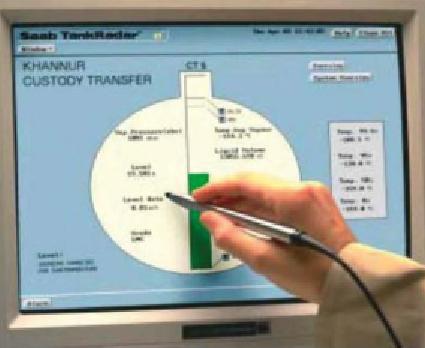
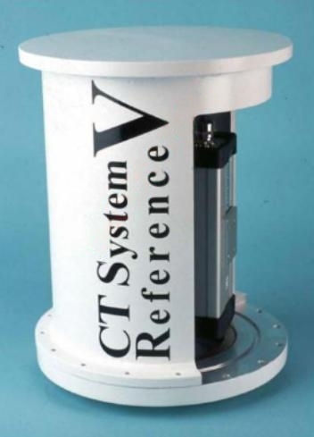
Outputs
A CTMS will output cargo data to the cargo control system for monitoring purposes. Figure 4 is an image of the Foxboro “Custody Transfer System Reference V” for LNG carriers, based on non-contact pulsed laser technology.
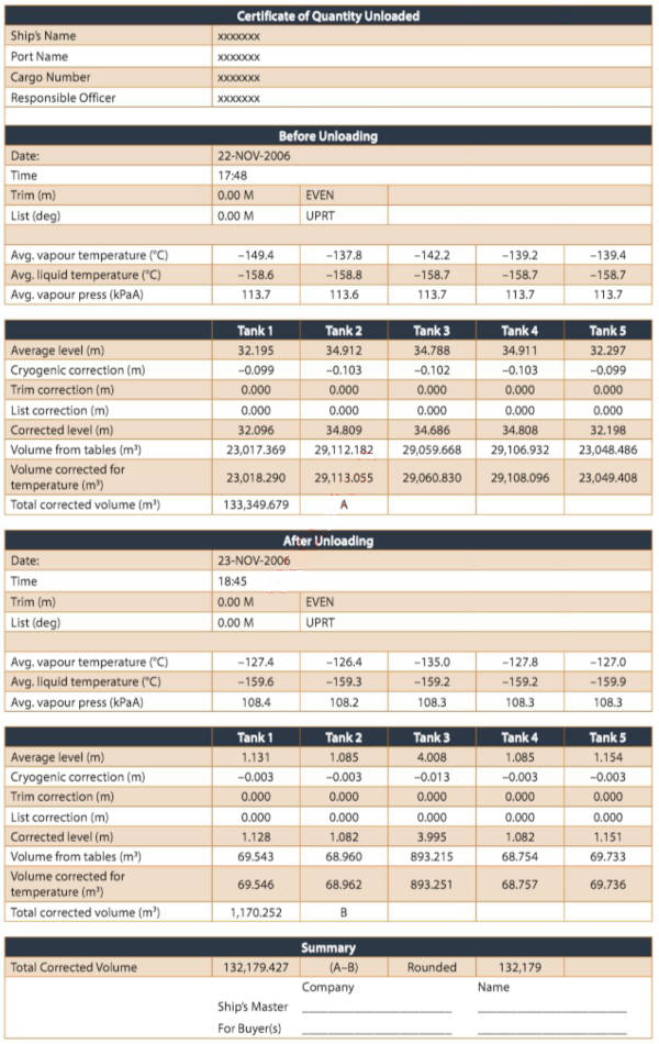
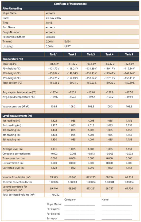
The CTMS reports are available for four stages:
- before loading;
- after loading;
- before discharge/unloading;
- after discharge/unloading.
Pre-loading
It is important that the CTMS and float gauges are cross-checked to ensure that accurate gauging is carried out Preparation of loading and unloading operations for LNG/LPG carriersbefore and after loading.
Prior to arriving at the load port, record the stowed/housed reading of the gauge and check it is correct.
When the ship is moored alongside, and before conducting the cargo survey, it is good practice to check all the float gauge readings against the CTMS readings. If there is a difference, proceed as follows:
- if the difference between the CTMS and the float gauge is more than 2 cm (and the stowed reading of the float gauge was correct) use the float gauge;
- if the difference is less than 2 cm use the CTMS.
After commencing load, cross-checks should be conducted at the 10 m and 20 m tank levels.

If the difference between the two systems has necessitated the use of the float gauge and the difference is less than 10 mm as the topping off level is approached, then the CTMS should be used for topping off. The OOW should stand by the local float gauge to call out the readings when topping off.
Post loading
Use the same gauging method that was used for the pre-loading survey. The CTMS and float gauge systems should again be cross checked.
Failure of the CTMS is likely to be the result of failure of the:
- level measuring system;
- temperature measuring system;
- pressure measuring system.
Failure of the primary level measuring system
If fitted, the back-up float level gauge should be brought in to use. If the float gauge is used for the initial tank measurement/survey, it should be also used for the final measurement. However, should the primary gauge fail during the load or discharge the final measurement must be made using the back-up float gauge.
In this case the volume calculations and corrections may have to be made by hand, using the tank gauge tables. However, on newer ships the secondary gauging system can be fed into the CTMS direct.
Failure of temperature measuring system
As the cargo tank cannot be entered when gassed up or containing LNG, to reduce the necessity of taking a tank or an LNGC out of service for repairs, two sets of temperature sensors are fitted in Cargo containment system of gas vesseleach cargo tank. One set is the “main system” and the other is the “back-up system”.
To provide this back-up capability, the temperature sensors are fitted at each (tank height specific) measuring point. As all the sensors have independent wiring, it is possible to use any mixture of main and back-up temperature sensors from the measuring levels (though only one from any level), i. e. 0 %, 10 %, 95 % and 99,5 % from the main system and 50 % from the back-up system.
Recommendations for cargo transfer measurement
The International Standards Organisation (ISO) provides the main documentation and Mastering LNG Measurement – Essential Practices and Operational Insightsguidelines for measurement, quantity, sampling and testing.
However, even where parties agree on using the same ISO norm as their measurement standard, there can still be a potential conflict if differing standards (e. g. ISO 6976 or ISO 6578) are adopted by the parties, as values can have varying significant digits or round-off rules.
As an example, a density calculated with the revised Klosek McKinley might give a value of 464,269 kg/m3 but, under the same conditions, this density calculated with ISO 6578 will give 464,230 kg/m3. On a total cargo load this minor difference represents about 6 tons of cargo.
Losses due to measurement errors
These include spurious errors, obvious mistakes or misreadings, systematic errors and misinterpretations, such as:
- use of different standards and/or edition dates for gas chromatographic analyses, density and gross heating values at load and discharge port;
- use of the same standards but different with applications for physical constants, interpolation procedures, number of digits used and rounding-off practices;
- use of the same physical properties but at different conditions such as standard(+15 °C) or normal (0/+25 °C) temperature, gross heating value, gas density;
- measurement of the same volume in the same tank but by using different level gauges (automatic/manual), which may generate different values.
Wrong or inadequate sampling techniques can lead to important errors amounting up to ± 1 %. The procedure for sampling the installation, the location and the set up of the sampling system are of crucial importance. If the location of the sampling system is wrong, e. g. too close to a pipe elbow, the gross heating value will be under or overestimated.
Not taking into account the quantities remaining (ROB) or displaced (vapour) on board is also a common mistake.
Below are some calculations of the potential values of these amounts, estimating the impact of such losses on an average LNG shipload.
| Full or empty liquid lines on board (before versus after loading/discharge) | Average ship: 46 tons |
| Vapour phases accounted before/after discharge/loading | Difference: 192 tons |
| Gas boil-off (vapour return) during loading | Estimated 300 tons |
| Gas received by LNG carrier when unloading | Estimated 192 tons |
All of the above mentioned cargo quantities and subsequent energy values are, in many cases, not accounted for.
The value of the cargo is based on the measurement and quantity computation of the cargo on board of the ship. This is unusual in commodity trading, where the cargo value or quantity is usually expressed in “shore” figures. Shore based calculations are usually the official basis for quantity transfer and the cargo invoice. Most shore tanks are, in these circumstances, certified and controlled by an official state/government certified body (calibrated tanks and/or volume meters).
Validation of tank tables and recalibration of equipment. In the normal trade of LNG there is sufficient data to verify the various floating measurement objects (vessels) against the shore based measurement objects (tanks and/or reading meters). By comparison, evaluation of voyage data and multiple sets of measurements can provide a historical differentiation of each ship’s measurement performance against the official or accredited shore based systems. This is known as the “Vessel Experience Factor” (VEF), which indicates the overall inaccuracy of the ship against accredited (official) shore based systems.
Shipboard measurement – calibration tables
The basis for any reliable shipboard measurement is the ship’s calibration (volume) table. This table allows the measurer to derive the actual liquid volume (at the actual liquid temperature) for each measured liquid level (height) or vapour space height (ullage).
Most LNG carriers are officially calibrated by a standard method such as ISO8311, ISO9091-1, ISO9091-2, etc. The tanks should be recalibrated every ten years and, where modifications have taken place to tanks, piping, pumps, membranes, etc., the calibration should be verified once the work is complete.
Several LNG carriers have been operating for more than 10 years, and in some cases even above 20 years, without any form of re-check or re-calibration. However the European directive with regard to this point is very clear. Tanks used for the official custody transfer and quantity determinations should be re-calibrated every 10 years. Instrumentation used on board, such as level, pressure and temperature indicators should be re-calculated and certified after every 2 years.
Approval by authorities
The gauge tables may be approved by either the authorities of the countries concerned with the LNG sale and purchase or by an independent survey firm.
This approval may be valid for a limited duration, generally 10 to 12 years, provided there are no modifications to the tanks.
For spherical tanks, owing to their geometry, the volume inaccuracy as a result of the small inaccuracies of the level gauge, Is significantly less than for prismatic tanks.
Great article on CTMS solutions for LNG carriers!
It’s really helpful to see how these systems ensure accuracy during custody transfer of LNG, since even small measurement errors can lead to major financial discrepancies between seller and buyer. I especially liked the focus on efficiency and reliability aspects.
It would be even more interesting if you could expand a bit on the technologies involved — for example, radar-based level gauges, Coriolis mass flow meters, or error-correction algorithms.
Overall, very useful and well-structured material. Thanks for sharing!