Digital Selective Calling (DSC) is a globally standardized maritime radio communication system that provides a reliable and efficient means for ships to communicate with each other and with shore-based stations. DSC system operates within the Global Maritime Distress and Safety System (GMDSS), serving as a fundamental component for ensuring maritime safety.
This article delves into the foundational aspects of DSC, exploring its role within the broader context of maritime communication. We will examine the individual elements that constitute a DSC call, providing a detailed breakdown of the various components involved in this specialized communication protocol.
Background
Under the “old” system, the procedure for calling a ship has always involved using traffic lists, or special calling channels. Ship stations have had to keep listening watch on the distress and calling channels (2 182 kHz, 500 kHz or VHF channel 16), or listen to traffic lists from relevant coast stations. The need to be able to call an individual ship station directly, without directing all ships to keep manual watch on the different calling channels, has been a high priority demand for a long time.
The present system has fundamental disadvantages which have provided the reasons for developing the new calling system, DSC, which is a very essential part of the GMDSS.
The Digital Selective Calling-DSC During Disasters or EmergenciesDSC system employs digital technology and is an important part of the GMDSS system, being used as the primary alerting system on VHF, MF and the HF bands.

Source: AI generated image
The DSC control unit is able to monitor/keep watch on all DSC frequencies allocated for distress and safety purposes. When a coast station or a ship receives a DSC Distress Signals And Distress Trafficdistress alert, a display or printout of the message will be produced including notification that distress communication will follow on the radiotelephony/radiotelex frequencies allocated for distress and safety purposes. In addition to the printout of the message, an audible/visual alarm will be activated to attract the attention of the operator.
Read also: Ship’s Antennas Systems and Radio Wave Propagation
DSC calls can be directed to a particular station or stations. Under the “old” system, virtually all calls were received by all ships within range of the transmission. Now, however, the DSC control unit checks each incoming call, and determines whether the call is addressed to it specifically. When such a call is received, the attention of the operator is attracted usually by a printout/display of the message or by audible/visual alarms. All other DSC calls that not are recognised by the DSC controller, are simply ignored.
DSC
DSC is a system used for calling:
- a particular ship;
- a particular coast station;
- a group of ships (within a certain geographical area);
- all ships.
The system can be used from:
- ship to shore;
- shore to ship;
- ship to ship.
The ships must be fitted with mandatory DSC equipment, applicable to the sea areas in which they sail.
The various different DSC requirements are listed below.
VHF DSC
All GMDSS ships must be fitted with VHF DSC channel 70 for distress and safety calls from ship to ship. In sea area A1, ships must also be able to execute distress and safety calls to a coast station.
MF DSC
All GMDSS ships sailing in sea areas A2, A3 and A4, must be fitted to accommodate the 2 187,5 kHz frequency for distress and safety calls from ship to ship. In sea area A2, the ship must be able to execute distress and safety calls between ship and coast station.
HF DSC
GMDSS ships sailing in sea area A4, and those without INMARSAT terminals sailing in sea area A3, must be equipped with DSC for VHF and MF.
In addition the ship must be equipped with HF DSC for distress and safety calls between ship and coast station.
The DSC equipment (control unit) is designed in such a way that the equipment itself puts the calling sequence together in the correct order.
To make a complete call, the radio operator only needs to type in the relevant information.
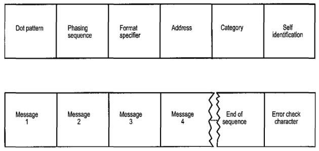
The Individual Elements of the DSC Call
Dot pattern: A sequence of dots transmitted so that the scanning-receivers can be tuned, and stop scanning.
Phasing sequence: In-phasing signals making the receiver ready for reception of information from the DSC transmitter.
Format specifier: Call Specifications:
- Distress call.
- All ships call.
- Call for specific groups of ships (All Norwegian ships, ships belonging to a fleet etc.).
- Selective calling to one specific ship.
- Call to ships in a certain geographical area.
- Dialphone call for direct access to the subscriber network.
Address:
- The MMSI number of the ship or the coast station which is being called.
Exemptions are made for accidents or distress alerting, and “all ships” calls.
Category: The type of call such as:
- Distress.
- Urgency.
- Safety.
- Important ships traffic.
- Routine.
Self identification: The ship’s own MMSI number
Message: The number of “Messages” may vary according to different kinds of traffic.
This element will be further examined under distress and routine calls.
Message 1: Distress call: Message 1 describes the distress situation.
- Fire/explosion.
- Leakage.
- Collision.
- Grounding.
- Listing, danger of capsizing.
- Sinking.
- Drifting.
- Unspecified.
- Abandoning.
- EPIRB transmission.
- Man overboard.
- Armed robbery attack.
Message 2: Message 2 describes the distress position by means of 10 digits.
- Quadrant specification, 1 digit:
- 0: North east.
- 1: North west.
- 2: South east.
- 3: South west.
- The next four digits denote the latitude in degrees and minutes.
- The next five digits denote the longitude in degrees and minutes.
NOTE: If The Global Maritime Distress and Safety System – Principles & Practicedistress position is not stated, the digit “9” is transmitted 10 times.
Message 3: Message 3 provides the point in time when the position was correct. It is given in UTC time by means of four digits.
- Digits 1 and 2 denote HOURS.
- Digits 3 and 4 denote MINUTES.
NOTE: If the point in time is not stated, the digit “8” is transmitted 4 times.
Message 4: Message 4 describes the kind of communication desired for the distress traffic (normally voice communication) which will follow.
End of sequence: Now an end message is transmitted to indicate:
- whether the call requires acknowledgement;
- whether the current message is a reply to a call.
Error check character: An error check character is transmitted as a control bit for the entire call.
DSC routine call
A DSC system routine call includes the same elements as described above, except that it uses only Message 1 and Message 2.
These two elements are described below:
Message 1: Routine call:
- Message 1 indicates whether connection is to be made by means of telephony, telex or data transmission.
Message 2: Routine call:
- Message 2 indicates the frequency/channel for the following communication.
Selective calling numbers in GMDSS
The national Administration, or another office/institute acting on behalf of the national Administration, assigns MMSI numbers to ships.
The number consists of 9 digits:
MID XXX XXX
MID is the Maritime Identification Digit, and identifies the nationality of the ship.
Norwegian ships have MIDs 257,258 and 259.
Current status of MID allocations is found in ITU “Manual for use by the Maritime Mobile and Maritime Mobile-Satellite Services”.
The MID group is followed by 6 digits, where the last digit is always “0” (zero).
For most larger ships, the three last digits are zeroes.
THE MMSI NUMBER SHALL BE USED FOR IDENTIFYING THE FLOAT FREE EPIRB, AND VHF/MF/HF DSC EQUIPMENT.
Above, we have seen that the MMSI number consists of 9 digits. But we also distinguish between three Regulations and Traffic Proceduresdifferent call identities. Study the following figure:


- Global Maritime Distress and Safety System: IMO 1987.
- Manual for use by The Maritime Mobile and Maritime Mobile- Satellite Services: ITU 1992.
- Radio Regulations 1-2-3: ITU 1990.
- Manual for Norwegian Mobile Radiotelephone Stations: The Norwegian Telecom 1992.
- Modem Electronic Communication: Gary M. Miller 1978.
- Brochures and data sheets from manufacturers of GMDSS Equipment.
- Inmarsat: Inmarsat-A User’s Manual, Inmarsat-C User’s Manual.
- Nodposisjonering: Bjomar Augdal, 1992.
- Skipsantenner: Bjomar Augdal 1991.
- COSPAS-SARSAT Secretariat: COSPAS-SARSAT System Data Documents.
- Admiralty List of Radio Signals.