Radio communication, an indispensable technology in modern society, relies on the transmission and reception of electromagnetic waves within the radio frequency spectrum. Find out how ship’s antennas work and what types of them exist.
- General Information
- Radio waves
- Antenna length and resonance frequency
- Radio wavelengths and frequencies
- Unit of measurement Hertz (Hz)
- MF Antenna lengths
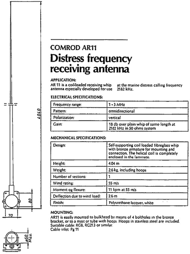
- MF Emergency antenna
- Propagation of Radio Waves
- The Ionosphere
- VHF (very high frequency)
- MF (medium wave)
- HF (high frequency)
- Inmarsat-A/B antennas
- Inmarsat-C antennas
- Simplex transmission
- Duplex transmission
- Antenna maintenance
- Wire antennas
- Whip antennas
- Coax cable
- Cable connectors/plugs
We will examine various transmission modes, including simplex and duplex, and discuss the critical role of antenna maintenance in ensuring reliable communication. From the intricacies of MF (medium wave) and HF (high frequency) bands to the specialized designs of Inmarsat-A/B and Inmarsat-C antennas, this overview will provide a comprehensive understanding of the core elements underpinning radio communication systems.
General Information
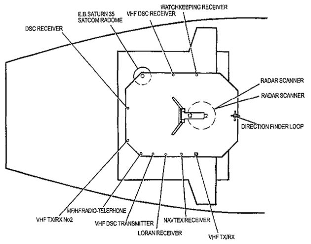
A ship’s antenna arrangement consists of several different transmitter and receiver antennas, and the available space on board is very limited.
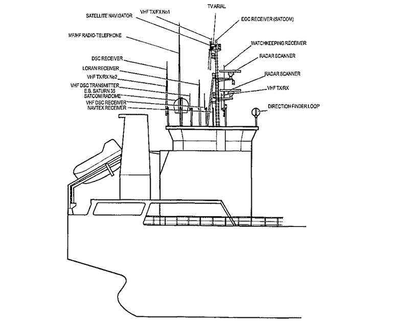
Therefore, the antenna locations are often a result of various compromises. The design of the antenna arrangement is of major importance when it comes to the amount of radiated power available and the reception of different radio signals.
Radio waves
A radio transmission consists of electromagnetic waves (an electric and a magnetic field), and the task of the transmitter antenna is to convert the high frequency antenna current into electromagnetic radiation.
Antenna length and resonance frequency
The electrical length and conductivity of the antenna is very important, especially on the medium wave (MF) and high frequency (HF) bands.
The antenna insulators are also of considerable importance and must be of sufficient size and quality to maintain enough antenna-to-ground resistance in humid weather. Receiver antennas are designed to pick up radio signals and transform them into high frequency (HF) voltage and current which is conducted to the RF (radio frequency) amplifier in the receiver.
As mentioned above, the electrical length of the antenna is very important when it comes to the amount of radiated power. To obtain maximum radiation for a designated frequency, the antenna must be tuned to the correct electrical length. However, on board a ship the available space is very limited, and this is therefore impossible to achieve.
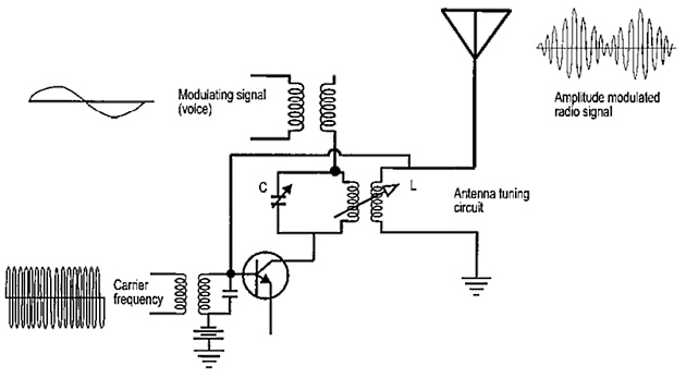
By using electronic components such as coils and capacitors, it is possible to “create” the correct antenna length. These components are in use in the “antenna tuner” when the transmitter tunes the frequency to resonance and maximum antenna current.
Read also: Emergency Preparedness: The Role of EPIRBs and SARTs in Maritime Safety
When the maximum antenna current is gained, the antenna is in resonance with the chosen frequency, and the antenna oscillates with the same frequency as Basic transmitters and receivers in shippingthe transmitter. The example below shows the principle of a simple antenna tuning circuit, for AM (amplitude modulation).
The antenna is tuned to the resonance frequency by means of the coil (L) and the capacitor (C).
Radio wavelengths and frequencies
Propagation speed
The propagation speed of Exploring Radio Paths, Spectrum, and Propagation Mechanismsradio waves is equal to the speed of light, which is approximately 300 000 km/sec. or 300 000 000 meter/sec.
The following equation shows the ratio between the propagation speed of radio waves (C), the wavelength (lambda), and the frequency (f):
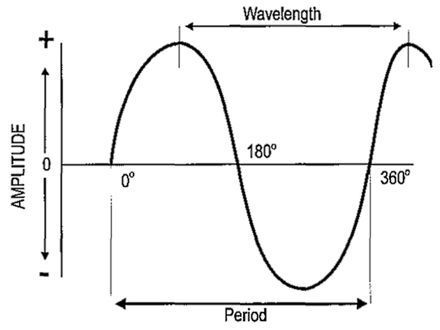
Wavelength
The wavelength, symbolized by the greek letter lambda, is the distance from one wave top to another.
Period
A period, or cycle, is the time it takes for a wave to move from zero to 360 degrees.
Unit of measurement Hertz (Hz)
The unit used for measuring frequency is Hertz, symbolized by Hz, and signifying the number of periods per second. A radio wave is often several million Hertz, but using such large numbers is often inconvenient.
Example No. 1:
- 1 THz (Terra Hz) = 1 000 000 000 000 Hz;
- 1 GHz (Giga Hz) = 1 000 000 000 Hz;
- 1 MHz (Mega Hz) = 1 000 000 Hz;
- 1 kHz (Kilo Hz) = 1 000 Hz.
Example No. 2:
The ship-to-shore alerting channel for VHF DSC is channel 70, at a frequency of 156.525 MHz. This frequency can also be expressed as:
By using the formula C = F · lambda, we can calculate either the frequency or the wavelength, as long as we know one of these two values.
or
Example No. 3:
Again using the frequency for VHF channel 70, we can calculate the wavelength for this frequency:
Example No. 4:
If the wavelength is 600 meters, it is quite simple to calculate the frequency:
MF Antenna lengths
In the medium wave (MF) frequency range, from 1 605 kHz to 4 000 kHz, the electrical length of the antenna is always a quarter of the total wavelength.
MF Emergency antenna
In some cases, it may be necessary to replace a damaged antenna, your MF/HF antenna, for instance. NON-DSC Terrestrial Distress CommunicationsThe distress frequency on the MF band is 2 182 kHz. To find the correct length of the antenna wire, you have to calculate a quarter of the total wavelength.
Example No. 5:
So, when replacing your damaged antenna, you can exchange it with a wire antenna with a length of 34,4 metres.
| Table of wavelengths | ||
|---|---|---|
| ELF = extremely low frequency | 3 Hz – 3 kHz | 100 000 km – 100 km |
| VLF = very low frequency | 3 kHz – 30 kHz | 100 km – 10 km |
| LF = low frequency | 30 kHz – 300 kHz | 10 km – l km |
| MF – medium frequency | 300 kHz – 3 MHz | 1 km – 100 m |
| HF = high frequency | 3 MHz – 30 MHz | 100 m – 10 m |
| VHF = very high frequency | 30 MHz – 300 MHz | 10 m – 1 m |
| UHF = ultra high frequency | 300 MHz – 3 GHz | 1 m – 10 cm |
| SHF = super high frequency | 3 GHz – 30 GHz | 10 cm – 1 cm |
| EHF = extremely high frequency | 30 GHz – 300 GHz | 1 cm – 1 mm |
Propagation of Radio Waves
The Ionosphere
The upper part of the atmosphere consists of several layers of electri cally charged particles known as the ionosphere. The ionosphere is composed of three layers designated respectively, from lowest level to highest level, as D, E, and F.
The F layer is further divided into two layers designated as F1 (the lower level) and F2 (the higher level). The presence, or absence, of these layers in the ionosphere, and their height above the earth, vary with the position of the sun.
It will be interesting: Empowering Global Communication with INMARSAT Satellites in shipping
When measured directly above a given point, solar radiation in the ionosphere is greatest at noon, while at night it is at a minimum. When the radiation is removed, many of the free ions and electrons which were ionized will recombine into neutral atoms. During the interval of time between these conditions, the position and number of the ionized layers within the ionosphere changes. Since the position of the sun varies with respect to a specified point on earth daily, monthly, and yearly, the exact characteristics of the layers are extremely difficult to predict. However, the following general statements can be made:
The D layer
The D layer ranges from distances of approximately 40 km to 90 km from the earth. Ionization of the D layer is low, because it is the lowest region of the ionosphere.
This layer has the ability to refract signals of low frequencies. High frequencies pass right through it but are attenuated in so doing. After sunset the D layer disappears because of the rapid recombination of its ions.
The E layer
The E layer is confined to distances of approximately 90 to 145 km from the Earth. The rate of ionic recombination in this layer is quite rapid after sunset and is almost complete by midnight.
This layer has the ability to refract signals of higher frequency than those refracted by the D layer. In fact, the E layer can refract signals with frequencies as high as 20 MHz.
The F layer
The F layer exists at distances from about 145 km to 400 km from the Earth’s surface. During daylight, the F layer separates into two layers, the F1 and F2 layers.
The ionization level of these layers is quite high and varies widely during the course of a day. At noon, this portion of the atmosphere is closest to the sun, and the degree of ionization is maximum. Since the atmosphere is rarefied at these heights, the recombination of the ions occurs slowly after sunset. Therefore, a fairly constant ionized layer is present at all times.
The F layer allows high-frequency long distance transmissions due to its refractive capabilities for frequencies up to 30 MHz, and also due to the long skip distance provided by refraction from such high elevation.
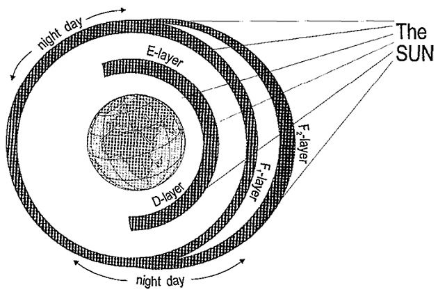
The D-layer, 40 – 90 km from the Earth; The E-layer, 90-145 km from the Earth; The F-layer, 145 – 400 km from the Earth
VHF (very high frequency)
The typical VHF antenna is an omnidirectional antenna radiating the radio signals in all directions. The VHF The Structure, Functions and Details of Professional Marine Radio Communicationcommunication system is also called a line-of-sight communication system, because the range of the transmission is limited to open or free visibility between the transmitting antenna and the receiving antenna.
Frequencies higher than 30 MHz are normally not refracted in the ionosphere, and the VHF radio waves follow the Earth’s surface only to a lesser extent.
The range of a VHF communication system can be calculated by the following formula:
Where h1 and h2 are antenna height in meters.
The same equation expressed in miles:
Where h1 and h2 are antenna height in feet.

MF (medium wave)
The medium wave band (MF) consists of frequencies between 1 605 and 4 000 kHz. This band is also called the coast telephony band.
The propagation of radio waves can be described in the following way: In the day time, the radio waves are propagated only along the surface of the earth, as ground waves. The safe communication range is about 150 nautical miles, 280 km.
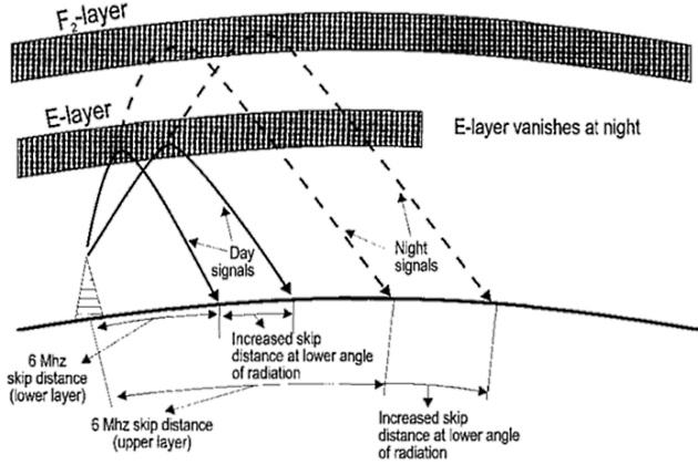
At night, the radio waves are more or less refracted by the E layer of the ionosphere, and the range will increase considerably.
As previously mentioned, the intensity of the layers of the ionosphere is dependent on the radiation of energy from the sun, therefore the ionosphere’s refraction ability will vary from day to night time.
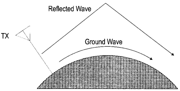
During the day, the radio horizon is only approx. 150 nautical miles (Ground wave propagation). At night reflections occur, and the range is increased.
HF (high frequency)
High frequency communication is based on the refraction of signals in the F-layer of the ionosphere.
HF communication is also called sky wave communication. Sky waves are those waves radiated from the transmitting antenna in a direction that produces a large angle in relation to the Earth.
A sky-wave has the ability to strike the ionosphere, be refracted back to the ground, strike the ground, be reflected back to the ionosphere, and so on.
The refraction and reflecting action of the ionosphere and the ground is called skipping.
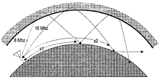
The figure on the previous page shows the relationship between frequency and refraction in the ionosphere, and different skip distances. The skip distance is increased by a lower angle of radiation.
Inmarsat-A/B antennas
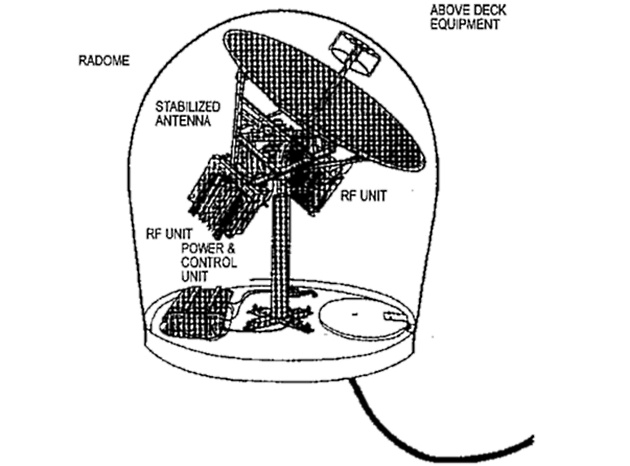
The INMARSAT–A/B terminal uses a parabolic dish antenna. The figure on the next page shows the Above Deck Equipment (ADE) of the SATURN 3S 90 antenna system by ABBNERA (NORWAY). The antenna is capable of tracking (following) the satellite by means of an auto-tracking system. The gyro stabilization framework takes care of pitch and roll compensation.
This antenna works with frequencies in the range of 1,5 – 1,6 GHz. The antenna framework and the power/control unit is protected by a radome.
Read also: Terrestrial Urgency and Safety Communications on the Vessels
Ideally, the antenna must have free visibility in all directions over an elevation of 5 degrees.
Also, the radome should be kept at least 5 meters away from the HF-antenna, and 3 meters or more from magnetic compasses. The radome should also be kept away from the rotating area of the radar scanner, and heat and smoke from the funnel.
Requirements concerning antenna locations are provided by the «Inmarsat Guidelines» and IMO Res. A.608(15).
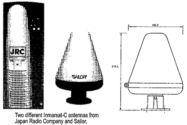
Inmarsat-C antennas
The INMARSAT–C is an omnidirectional antenna. This type of antenna must be placed as high and free as possible. The frequency range is the same as that of the INMARSAT–A system, 1,5 – 1,6 GHz.
The antenna interface is a standard 50 ohm coax cable. In accordance with the manufacturer’s specifications, the antenna can be mounted up to 100 meters away from the transceiver unit.
Simplex transmission
In a simplex communication system, only one frequency is used. This means that both transmitter and receiver are tuned to the same frequency, and only one station at a time is able to transmit.
Duplex transmission
In Importance of Reliable Marine Communications and Empowering Maritime Industryduplex communication systems, two different frequencies are used. One frequency for transmission, and one for reception.
Receiver (RX): 8 779 kHz
Transmitter (TX): 8 255 kHz
A basic rule employed to gain best possible duplex conditions, is to separate the TX antenna from the RX antenna as much as possible, and in addition, ensure that the highest possible frequency separation is achieved.
Another term used in communication is «semiduplex», which involves the possibility of two-way communication, but not simultaneously.
Antenna maintenance
Wire antennas
Wire antenna insulators and lead-in insulators must be regularly cleaned to remove soot and salt.
It will be interesting: Basic Concepts of the GMDSS
A low antenna-to-ground resistance will lead to reduced signal radiation, and the efficiency of the antenna will be reduced. Damaged antenna wire and insulators should be replaced.
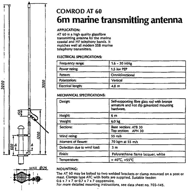
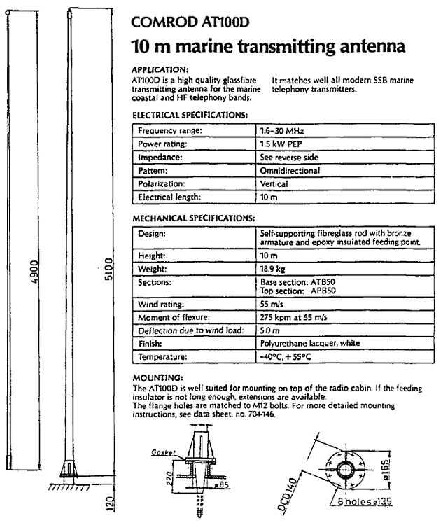
Whip antennas
Whip antennas are often made of fibreglass material. Swaying over a long period due to wind, may cause tiny cracks in the fiberglass material, and thus allow the penetration of water into the copper wire. This will create a path of conduction to ground and reduce the amount of radiated power.
Antennas with a bad coating, or no coating at all, should be replaced.
Coax cable
The most commonly used coax cables on board ships have an impedance of 50 ohms. If the cable is damaged by water leakage, the impedance of the cable will alter.
The result will be antenna mismatch and too much reflected power. Another possible result may be a short circuit of the transmitter’s power amplifier stage.
Cable connectors/plugs
The most commonly used connectors are UHF or N-connectors. The connectors can be cleaned by using different types of electronic cleaners.
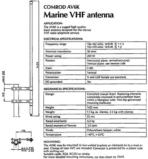
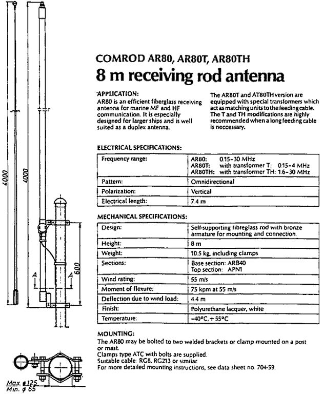
Different types of ship’s antennas from COMROD A/S (Ltd)

- Global Maritime Distress and Safety System: IMO 1987.
- Manual for use by The Maritime Mobile and Maritime Mobile- Satellite Services: ITU 1992.
- Radio Regulations 1-2-3: ITU 1990.
- Manual for Norwegian Mobile Radiotelephone Stations: The Norwegian Telecom 1992.
- Modem Electronic Communication: Gary M. Miller 1978.
- Brochures and data sheets from manufacturers of GMDSS Equipment.
- Inmarsat: Inmarsat-A User’s Manual, Inmarsat-C User’s Manual.
- Nodposisjonering: Bjomar Augdal, 1992.
- Skipsantenner: Bjomar Augdal 1991.
- COSPAS-SARSAT Secretariat: COSPAS-SARSAT System Data Documents.
- Admiralty List of Radio Signals.